Integrating Voice Architectures
![]() This section discusses integrated voice architecture concepts, components, mechanisms, and issues. Integrated networks are described, and the H.323 standard is introduced. IP telephony is presented and call control and transport protocols are discussed.
This section discusses integrated voice architecture concepts, components, mechanisms, and issues. Integrated networks are described, and the H.323 standard is introduced. IP telephony is presented and call control and transport protocols are discussed.
 Introduction to Integrated Networks
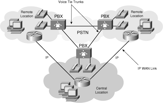
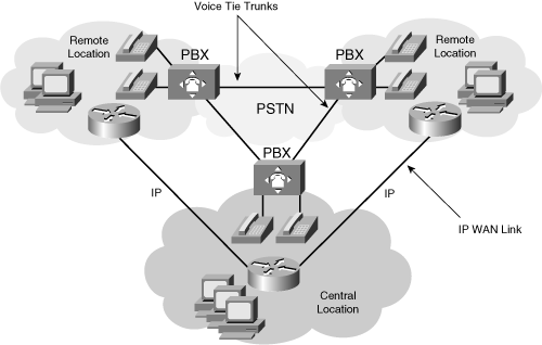
![]() Figure 8-14 illustrates a typical enterprise WAN with separate data and voice networks.
Figure 8-14 illustrates a typical enterprise WAN with separate data and voice networks.
![]() Integrating data, voice, and video in a network enables vendors to introduce new features. The unified communications network model enables distributed call routing, control, and application functions based on industry standards. Enterprises can mix and match equipment from multiple vendors and geographically deploy these systems wherever they are needed.
Integrating data, voice, and video in a network enables vendors to introduce new features. The unified communications network model enables distributed call routing, control, and application functions based on industry standards. Enterprises can mix and match equipment from multiple vendors and geographically deploy these systems wherever they are needed.
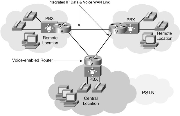
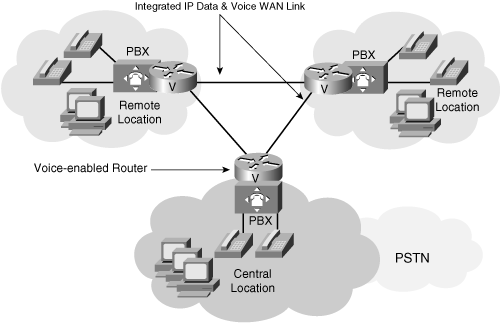
![]() One means of creating an integrated network is to replace the PBXs’ voice tie trunks with IP connections by connecting the PBXs to voice-enabled routers. The voice-enabled routers convert voice traffic to IP packets and direct them over IP data networks. This implementation is called VoIP. Figure 8-15 illustrates an integrated network using VoIP over an IP WAN link that carries voice and data at the same time.
One means of creating an integrated network is to replace the PBXs’ voice tie trunks with IP connections by connecting the PBXs to voice-enabled routers. The voice-enabled routers convert voice traffic to IP packets and direct them over IP data networks. This implementation is called VoIP. Figure 8-15 illustrates an integrated network using VoIP over an IP WAN link that carries voice and data at the same time.
![]() IP telephony, a superset of VoIP, is another implementation. IP phones are used, and the phones themselves convert the voice into IP packets. A dedicated network server that runs specialized call processing software replaces the PBX; in Cisco networks, this is the Cisco Unified Communications Manager. IP phones are not connected with telephone cabling. Instead, they send all signals over standard Ethernet. The “Introduction to IP Telephony” section later in this chapter provides details of this solution.
IP telephony, a superset of VoIP, is another implementation. IP phones are used, and the phones themselves convert the voice into IP packets. A dedicated network server that runs specialized call processing software replaces the PBX; in Cisco networks, this is the Cisco Unified Communications Manager. IP phones are not connected with telephone cabling. Instead, they send all signals over standard Ethernet. The “Introduction to IP Telephony” section later in this chapter provides details of this solution.
| Note |
|
Drivers for Integrating Voice and Data Networks
![]() Although a PSTN is effective for carrying voice signals, many business drivers are forcing the need for a new type of network for the following reasons:
Although a PSTN is effective for carrying voice signals, many business drivers are forcing the need for a new type of network for the following reasons:
-
 Data has overtaken voice as the primary traffic on many voice networks.
 -
 Companies want to reduce WAN costs by migrating to integrated networks that can efficiently carry any type of data.
 -
 The PSTN architecture was designed and built for voice and is not flexible enough to optimally carry data.
 -
 The PSTN cannot create and deploy features quickly enough.
 -
 Data, voice, and video cannot be integrated on the current PSTN structure.
![]() IP telephony is cost-effective because of the reduced number of tie trunks and higher link efficiency, and because both voice and data networks use the same WAN infrastructure. It is much easier to manage a single network than two separate networks, because doing so requires fewer administrators, a simplified management infrastructure, and lower administrator training costs.
IP telephony is cost-effective because of the reduced number of tie trunks and higher link efficiency, and because both voice and data networks use the same WAN infrastructure. It is much easier to manage a single network than two separate networks, because doing so requires fewer administrators, a simplified management infrastructure, and lower administrator training costs.
![]() On an IP network, voice servers and application servers can be located virtually anywhere. The rationale for enterprises to maintain voice servers, as with data application servers, is diminishing over time. As voice moves to IP networks (using the public Internet for inter-enterprise traffic and private intranets for intra-enterprise traffic), service providers might host voice and application servers.
On an IP network, voice servers and application servers can be located virtually anywhere. The rationale for enterprises to maintain voice servers, as with data application servers, is diminishing over time. As voice moves to IP networks (using the public Internet for inter-enterprise traffic and private intranets for intra-enterprise traffic), service providers might host voice and application servers.
 H.323
H.323
Introduction to H.323
![]() The ITU-T H.323 standard is a foundation for audio, video, and data communications across IP-based networks, including the Internet. By complying with the H.323 standard, multimedia products and applications from multiple vendors can interoperate, thereby allowing users to communicate without concern for compatibility.
The ITU-T H.323 standard is a foundation for audio, video, and data communications across IP-based networks, including the Internet. By complying with the H.323 standard, multimedia products and applications from multiple vendors can interoperate, thereby allowing users to communicate without concern for compatibility.
![]() The H.323 standard is broad in scope and includes standalone devices (such as IP telephones and voice gateways), embedded personal computer technology (such as PCs with Microsoft’s NetMeeting), and point-to-point and multipoint conferencing. H.323 includes call control (including session setup, monitoring, and termination), multimedia management, bandwidth management, and multicast support in multipoint conferences.
The H.323 standard is broad in scope and includes standalone devices (such as IP telephones and voice gateways), embedded personal computer technology (such as PCs with Microsoft’s NetMeeting), and point-to-point and multipoint conferencing. H.323 includes call control (including session setup, monitoring, and termination), multimedia management, bandwidth management, and multicast support in multipoint conferences.
![]() Communications under H.323 are a mix of audio, video, data, and control signals. To establish a voice call, H.323 refers to other standards, including H.225 and H.245. The H.225 standard is based on the Q.931 protocol. It describes call signaling and the Registration, Admission, and Status (RAS) signaling used for H.323 session establishment and packetization between two H.323 devices. For example, the H.225 setup message has information elements that include the calling party number and the called party number. H.245 is a control standard for multimedia communication that describes the messages and procedures used for opening and closing logical channels for audio, video, and data, capability exchange, control, and indications.
Communications under H.323 are a mix of audio, video, data, and control signals. To establish a voice call, H.323 refers to other standards, including H.225 and H.245. The H.225 standard is based on the Q.931 protocol. It describes call signaling and the Registration, Admission, and Status (RAS) signaling used for H.323 session establishment and packetization between two H.323 devices. For example, the H.225 setup message has information elements that include the calling party number and the called party number. H.245 is a control standard for multimedia communication that describes the messages and procedures used for opening and closing logical channels for audio, video, and data, capability exchange, control, and indications.
![]() An H.323 conference can include endpoints with different capabilities. For example, a terminal with audio-only capabilities can participate in a conference with terminals that have video and data capabilities. An H.323 multimedia terminal can share the data portion of a videoconference with a data-only terminal while sharing voice, video, and data with other H.323 terminals.
An H.323 conference can include endpoints with different capabilities. For example, a terminal with audio-only capabilities can participate in a conference with terminals that have video and data capabilities. An H.323 multimedia terminal can share the data portion of a videoconference with a data-only terminal while sharing voice, video, and data with other H.323 terminals.
H.323 Components
![]() H.323 defines four major components for a network-based communications system: terminals, gateways, gatekeepers, and multipoint control units (MCU).
H.323 defines four major components for a network-based communications system: terminals, gateways, gatekeepers, and multipoint control units (MCU).
Terminals
![]() Terminals are client endpoints that provide real-time two-way H.323 communications with other endpoints, such as H.323 terminals, gateways, or MCUs. All terminals must support standard 64-kbps PCM-encoded voice communications; video and data are optional. Examples of H.323 terminals are IP telephones and PCs with Microsoft NetMeeting software.
Terminals are client endpoints that provide real-time two-way H.323 communications with other endpoints, such as H.323 terminals, gateways, or MCUs. All terminals must support standard 64-kbps PCM-encoded voice communications; video and data are optional. Examples of H.323 terminals are IP telephones and PCs with Microsoft NetMeeting software.
Gateways
![]() An H.323 gateway is an optional element in the voice network; it can be a voice-enabled router or switch. Gateways provide many services, such as translation between H.323 endpoints and non-H.323 devices, which allows H.323 endpoints and non-H.323 devices to communicate. In addition, the gateway also translates between audio, video, and data formats; converts call setup signals and procedures; and converts communication control signals and procedures.
An H.323 gateway is an optional element in the voice network; it can be a voice-enabled router or switch. Gateways provide many services, such as translation between H.323 endpoints and non-H.323 devices, which allows H.323 endpoints and non-H.323 devices to communicate. In addition, the gateway also translates between audio, video, and data formats; converts call setup signals and procedures; and converts communication control signals and procedures.
![]() Terminals use the H.245 and Q.931 protocols to communicate with H.323 gateways. An example of a gateway is a voice-enabled router providing a connection to the PSTN, a PBX, or an analog phone. An interface on a voice gateway that carries voice data is a voice port. A voice port is a physical port on a voice module; this is what makes a router voice-enabled.
Terminals use the H.245 and Q.931 protocols to communicate with H.323 gateways. An example of a gateway is a voice-enabled router providing a connection to the PSTN, a PBX, or an analog phone. An interface on a voice gateway that carries voice data is a voice port. A voice port is a physical port on a voice module; this is what makes a router voice-enabled.
![]() A voice module enables connectivity with traditional circuit-switched voice devices and networks. It converts voice into IP packets and vice versa. Specialized processors called digital signal processors (DSP) are located on the voice module and perform the coding and compressing of voice data. The following are some of the voice modules available on Cisco voice gateways:
A voice module enables connectivity with traditional circuit-switched voice devices and networks. It converts voice into IP packets and vice versa. Specialized processors called digital signal processors (DSP) are located on the voice module and perform the coding and compressing of voice data. The following are some of the voice modules available on Cisco voice gateways:
-
 ISDN PRI on an E1 or T1 voice module
 -
 E1-R2 signaling on an E1 voice module
 -
 T1-CAS signaling on a T1 voice module
 -
 FXS on a low-capacity voice module
 -
 FXO on a low-capacity voice module
 -
 ISDN BRI on a low-capacity voice module
Gatekeepers
![]() A gatekeeper is typically used in larger, more complex networks; the gatekeeper function can be performed by a Cisco IOS router or by third-party software. A gatekeeper serves as the central point for all calls within its zone and provides call control services to registered H.323 endpoints. All H.323 devices in the zone register with the gatekeeper so that the gatekeeper can perform its basic functions, such as H.323 address translation, admission control, bandwidth control, and zone management. Optionally the gatekeeper provides call control signaling, call authorization, bandwidth management, and call management.
A gatekeeper is typically used in larger, more complex networks; the gatekeeper function can be performed by a Cisco IOS router or by third-party software. A gatekeeper serves as the central point for all calls within its zone and provides call control services to registered H.323 endpoints. All H.323 devices in the zone register with the gatekeeper so that the gatekeeper can perform its basic functions, such as H.323 address translation, admission control, bandwidth control, and zone management. Optionally the gatekeeper provides call control signaling, call authorization, bandwidth management, and call management.
![]() The gatekeeper can balance calls among multiple gateways, either by integrating their addressing into the Domain Name System or via Cisco IOS configuration options. For instance, if a call is routed through a gatekeeper, that gatekeeper can forward the call to a corresponding gateway based on some routing logic. When an H.323 gatekeeper acts as a virtual voice switch, its function is known as gatekeeper-routed call signaling.
The gatekeeper can balance calls among multiple gateways, either by integrating their addressing into the Domain Name System or via Cisco IOS configuration options. For instance, if a call is routed through a gatekeeper, that gatekeeper can forward the call to a corresponding gateway based on some routing logic. When an H.323 gatekeeper acts as a virtual voice switch, its function is known as gatekeeper-routed call signaling.
| Note |
|
The Importance of a Gatekeeper
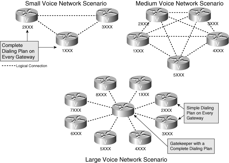
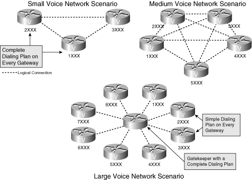
![]() Figure 8-16 illustrates some different voice design options and emphasizes the importance of a gatekeeper, especially in large voice network designs.
Figure 8-16 illustrates some different voice design options and emphasizes the importance of a gatekeeper, especially in large voice network designs.
![]() Voice network design depends primarily on the number of voice gateways and, consequentially, the number of logical connections between them. The maximum number of logical connections between voice gateways, and, as a result, the network’s complexity, can be calculated by the formula (N * (N−1))/2, where N is the number of voice gateways in the system. For example, the maximum number of logical connections between three voice gateways is three, between five voice gateways is ten, and between eight voice gateways is 28. The complexity of the network grows quickly with the number of gateways; adding one more voice gateway to an existing network means reconfiguring all other voice gateways, making network maintenance quite difficult. A solution for this issue is the use of a gatekeeper.
Voice network design depends primarily on the number of voice gateways and, consequentially, the number of logical connections between them. The maximum number of logical connections between voice gateways, and, as a result, the network’s complexity, can be calculated by the formula (N * (N−1))/2, where N is the number of voice gateways in the system. For example, the maximum number of logical connections between three voice gateways is three, between five voice gateways is ten, and between eight voice gateways is 28. The complexity of the network grows quickly with the number of gateways; adding one more voice gateway to an existing network means reconfiguring all other voice gateways, making network maintenance quite difficult. A solution for this issue is the use of a gatekeeper.
![]() Therefore, the configuration of a voice gateway becomes simpler and does not require modification when a new voice gateway is added to the system.
Therefore, the configuration of a voice gateway becomes simpler and does not require modification when a new voice gateway is added to the system.
Multipoint Control Units
![]() An MCU is an H.323 endpoint that enables three or more endpoints to participate in a multipoint H.323 conference. An MCU incorporates a multipoint controller (MC) and optionally one or more multipoint processors (MP).
An MCU is an H.323 endpoint that enables three or more endpoints to participate in a multipoint H.323 conference. An MCU incorporates a multipoint controller (MC) and optionally one or more multipoint processors (MP).
![]() The MC is the conference controller that handles H.245 capability negotiations between the endpoints and controls conference resources. An MC is not a standalone unit and can be located within an endpoint, terminal, gateway, gatekeeper, or MCU.
The MC is the conference controller that handles H.245 capability negotiations between the endpoints and controls conference resources. An MC is not a standalone unit and can be located within an endpoint, terminal, gateway, gatekeeper, or MCU.
![]() The MP handles the conference’s data streams. It receives multiple streams of multimedia input, switches and mixes the streams, and retransmits the result to the conference members. An MP resides in an MCU.
The MP handles the conference’s data streams. It receives multiple streams of multimedia input, switches and mixes the streams, and retransmits the result to the conference members. An MP resides in an MCU.
H.323 Example
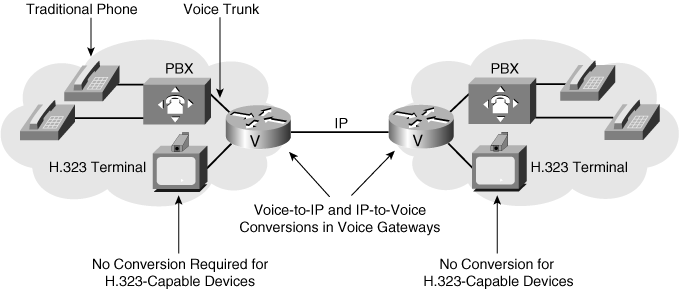
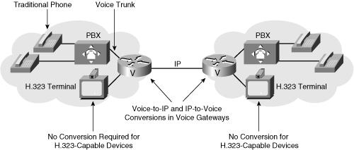
![]() Figure 8-17 illustrates the components typically involved in an H.323 call and the interactions between them.
Figure 8-17 illustrates the components typically involved in an H.323 call and the interactions between them.
![]() If traditional telephones are used and an IP network must transport calls, a voice gateway is required on both sides of the IP network. In this example, the gateway is a voice-enabled router that performs voice-to-IP and IP-to-voice conversions in DSPs. After the gateway router converts voice into IP packets, it transmits the packets across the IP network. The receiving router performs the same function in the reverse order: It converts IP packets to voice signals and forwards them through the PBX to the destination telephone.
If traditional telephones are used and an IP network must transport calls, a voice gateway is required on both sides of the IP network. In this example, the gateway is a voice-enabled router that performs voice-to-IP and IP-to-voice conversions in DSPs. After the gateway router converts voice into IP packets, it transmits the packets across the IP network. The receiving router performs the same function in the reverse order: It converts IP packets to voice signals and forwards them through the PBX to the destination telephone.
 Introduction to IP Telephony
![]() IP telephony refers to cost-effective communication services, including voice, fax, and voice-messaging applications, transported via the packet-switched IP network rather than the circuit-switched PSTN.
IP telephony refers to cost-effective communication services, including voice, fax, and voice-messaging applications, transported via the packet-switched IP network rather than the circuit-switched PSTN.
![]() The basic steps for placing an IP telephone call include converting the analog voice signal into a digital format, and compressing and translating the digital signal into IP packets for transmission across the IP network. The process is reversed at the receiving end.
The basic steps for placing an IP telephone call include converting the analog voice signal into a digital format, and compressing and translating the digital signal into IP packets for transmission across the IP network. The process is reversed at the receiving end.
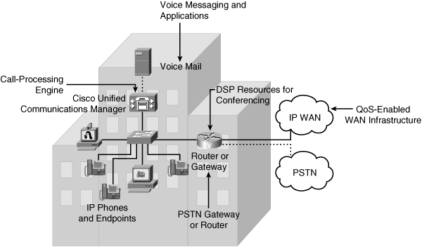
![]() The IP telephony architecture, illustrated in Figure 8-18, includes four distinct components: infrastructure, call processing, applications, and client devices. These components are described as follows:
The IP telephony architecture, illustrated in Figure 8-18, includes four distinct components: infrastructure, call processing, applications, and client devices. These components are described as follows:
-
 Infrastructure: The infrastructure is based on data link layer and multilayer switches and voice-enabled routers that interconnect endpoints with the IP and PSTN network. Endpoints attach to the network using switched 10/100 Ethernet ports. Switches may include Power over Ethernet (PoE) ports that sense the presence of IP devices that require inline power, such as Cisco IP phones and wireless access points, and provide that power. Voice-enabled routers perform conversions between the circuit-switched PSTN and IP networks.
 -
 Call processing: Cisco Unified Communications Manager is the software-based call-processing component of the Cisco enterprise IP telephony solution. Cisco Unified Communications Manager provides a scalable, distributable, and highly available enterprise IP telephony call processing solution and performs much like the PBX in a traditional telephone network, including providing call setup and processing functions.
 The Cisco Unified Communications Manager can be installed on Cisco MCS 7800 Series server platforms and selected third-party servers.
 -
 Applications: Applications provide additional features to the IP telephony infrastructure. Cisco Unity unified messaging (integrating e-mail and voice mail), Cisco Unified MeetingPlace (multimedia conferencing), Cisco Unified IP IVR, and Cisco Unified Contact Center products (including intelligent contact routing, call treatment, network-to-desktop computer telephony integration, and multichannel automatic call distribution) are among the Cisco applications available for IP telephony. The open-source application layer allows third-party companies to develop software that interoperates with Cisco Unified Communications Manager.
 -
 Client devices: Client devices are IP telephones and software applications that allow communication across the IP network. Cisco Unified Communications Manager centrally manages the IP telephones through Ethernet connections in the Building Access Layer switches.
IP Telephony Design Goals
![]() Typical design goals of an IP telephony network are as follows:
Typical design goals of an IP telephony network are as follows:
-
 End-to-end IP telephony: Using end-to-end IP telephony between sites where IP connectivity is already established. IP telephony can be deployed as an overlaid service that runs on the existing infrastructure.
 -
 Widely usable IP telephony: To make IP telephony widely usable, voice quality should be at the same level as in traditional telephony; this is known as toll quality voice.
 -
 Reduced long-distance costs: Long-distance costs should be lower than with traditional telephony. This can be accomplished by using private IP networks, or possibly the public Internet, to route telephone calls.
 -
 Cost-effective: Making IP telephony cost effective depends on using the existing WAN capacity more efficiently and the cost-of upgrading the existing IP network infrastructure to support IP telephony. In some cases, this goal can be accomplished by using the public Internet or private IP networks to route telephone calls.
 -
 High availability: To provide high availability, redundant network components can be used and backup power can be provided to all network infrastructure components, including routers, switches, and IP phones.
 -
 Lower total cost of ownership: IP telephony should offer lower total cost of ownership and greater flexibility than traditional telephony. Installation costs and operational costs for unified systems are lower than the costs to implement and operate two infrastructures.
 -
 Enable new applications on top of IP telephony via third-party software: For example, an intelligent phone used for database information access as an alternative to a PC is likely to be easier to use and less costly to own, operate, and maintain.
 -
 Improved productivity: IP telephony should improve the productivity of remote workers, agents, and stay-at-home staff by extending the productivity-enhancing enterprise telephony features such as voice mail and voice conferencing to the remote teleworker.
 -
 Facilitate data and telephony network consolidation: Such consolidation can contribute to operational and equipment savings.
![]() The following sections illustrate some sample IP telephony designs.
The following sections illustrate some sample IP telephony designs.
Single-Site IP Telephony Design
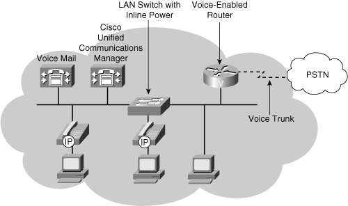
![]() Figure 8-19 illustrates a design model for an IP telephony network within a single campus or site.
Figure 8-19 illustrates a design model for an IP telephony network within a single campus or site.
![]() A single-site IP telephony design consists of Cisco Unified Communications Manager, IP telephones, LAN switches with inline power (PoE), applications such as voice mail, and a voice-enabled router, all at the same physical location. The IP telephones are powered through their Ethernet interface via the LAN switch. Gateway trunks are connected to the PSTN so that users can make external calls.
A single-site IP telephony design consists of Cisco Unified Communications Manager, IP telephones, LAN switches with inline power (PoE), applications such as voice mail, and a voice-enabled router, all at the same physical location. The IP telephones are powered through their Ethernet interface via the LAN switch. Gateway trunks are connected to the PSTN so that users can make external calls.
![]() Single-site deployment allows each site to be completely self-contained. All calls to the outside world and remote locations are placed across the PSTN. If an IP WAN is incorporated into the single-site model, it is for data traffic only; no telephony services are provided over the WAN. Therefore, there is no loss of the call processing service or functionality if an IP WAN failure occurs or if the WAN has insufficient bandwidth. The only external requirements are a PSTN carrier and route diversity within the PSTN network. As a recommended practice, use this model for a single campus or a site with fewer than 30,000 lines.
Single-site deployment allows each site to be completely self-contained. All calls to the outside world and remote locations are placed across the PSTN. If an IP WAN is incorporated into the single-site model, it is for data traffic only; no telephony services are provided over the WAN. Therefore, there is no loss of the call processing service or functionality if an IP WAN failure occurs or if the WAN has insufficient bandwidth. The only external requirements are a PSTN carrier and route diversity within the PSTN network. As a recommended practice, use this model for a single campus or a site with fewer than 30,000 lines.
Multisite WAN with Centralized Call Processing Design
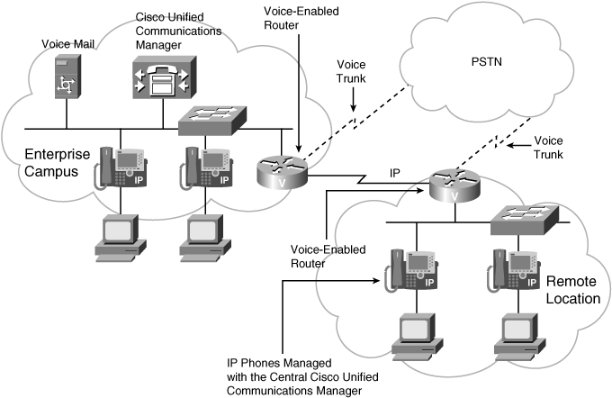
![]() Figure 8-20 presents a multisite WAN design model with centralized call processing; Cisco Unified Communications Manager at the central site connects to remote locations through the IP WAN. Remote IP telephones rely on the centralized Cisco Unified Communications Manager to handle their call processing. The IP WAN transports voice traffic between sites and carries call control signaling between the central site and the remote sites. Applications such as voice mail and IVR systems are also centralized, therefore reducing the overall cost of ownership and centralized administration and maintenance.
Figure 8-20 presents a multisite WAN design model with centralized call processing; Cisco Unified Communications Manager at the central site connects to remote locations through the IP WAN. Remote IP telephones rely on the centralized Cisco Unified Communications Manager to handle their call processing. The IP WAN transports voice traffic between sites and carries call control signaling between the central site and the remote sites. Applications such as voice mail and IVR systems are also centralized, therefore reducing the overall cost of ownership and centralized administration and maintenance.
![]() The remote locations require IP connectivity with the Enterprise Campus. IP telephones, powered by a local LAN switch, convert voice into IP packets and send them to the local LAN. The local router forwards the packets to the appropriate destination based on its routing table. In the event of a WAN failure, the voice-enabled routers at the remote sites can provide backup call processing functionality with Cisco Unified Survivable Remote Site Telephony (SRST) services. Cisco Unified SRST extends high-availability IP telephony to branch offices by providing backup call processing functionality on voice-enabled routers.
The remote locations require IP connectivity with the Enterprise Campus. IP telephones, powered by a local LAN switch, convert voice into IP packets and send them to the local LAN. The local router forwards the packets to the appropriate destination based on its routing table. In the event of a WAN failure, the voice-enabled routers at the remote sites can provide backup call processing functionality with Cisco Unified Survivable Remote Site Telephony (SRST) services. Cisco Unified SRST extends high-availability IP telephony to branch offices by providing backup call processing functionality on voice-enabled routers.
![]() If an enterprise requires high-quality voice communication over the WAN, the service provider must implement QoS mechanisms. Enterprises and service providers usually sign a service level agreement (SLA) that guarantees bandwidth and latency levels suitable for voice transport.
If an enterprise requires high-quality voice communication over the WAN, the service provider must implement QoS mechanisms. Enterprises and service providers usually sign a service level agreement (SLA) that guarantees bandwidth and latency levels suitable for voice transport.
| Note |
|
![]() As a recommended practice, use this model for a main site with many smaller remote sites that connect via a QoS-enabled WAN but that do not require full features and functionality during a WAN outage.
As a recommended practice, use this model for a main site with many smaller remote sites that connect via a QoS-enabled WAN but that do not require full features and functionality during a WAN outage.
Multisite WAN with Distributed Call Processing Design
![]() Figure 8-21 illustrates a multisite WAN design model with distributed call processing. This model consists of multiple independent sites, each with its own call processing agent and connected to an IP WAN that carries voice traffic between the distributed sites. The IP WAN in this model does not carry call control signaling between the sites because each site has its own call processing agent. Typically, the PSTN serves as a backup connection between the sites in case the IP WAN connection fails or has insufficient available bandwidth for incremental calls.
Figure 8-21 illustrates a multisite WAN design model with distributed call processing. This model consists of multiple independent sites, each with its own call processing agent and connected to an IP WAN that carries voice traffic between the distributed sites. The IP WAN in this model does not carry call control signaling between the sites because each site has its own call processing agent. Typically, the PSTN serves as a backup connection between the sites in case the IP WAN connection fails or has insufficient available bandwidth for incremental calls.
| Note |
|
![]() As a recommended practice, use this model for a large central site with more than 30,000 lines or for a deployment with more than six large sites (more than 30,000 lines total) interconnected via a QoS-enabled WAN.
As a recommended practice, use this model for a large central site with more than 30,000 lines or for a deployment with more than six large sites (more than 30,000 lines total) interconnected via a QoS-enabled WAN.
| Note |
|
 Call Control and Transport Protocols
![]() Voice communication over IP is a mix of call control signals and voice conversations coded and possibly compressed into IP packets. Both reliable (connection-oriented) and so-called “unreliable” (connectionless) transmissions are required for voice communication.
Voice communication over IP is a mix of call control signals and voice conversations coded and possibly compressed into IP packets. Both reliable (connection-oriented) and so-called “unreliable” (connectionless) transmissions are required for voice communication.
![]() Reliable transmission guarantees sequenced, error-free, flow-controlled transmission of packets. However, because reliable transport is connection-oriented, it can delay transmission and reduce throughput. TCP provides reliable transport in the IP stack, and all voice call control functions make use of it.
Reliable transmission guarantees sequenced, error-free, flow-controlled transmission of packets. However, because reliable transport is connection-oriented, it can delay transmission and reduce throughput. TCP provides reliable transport in the IP stack, and all voice call control functions make use of it.
![]() The User Datagram Protocol (UDP), which provides best-effort delivery, supplies connectionless transmission in the IP stack and is used for voice conversation transport between two endpoints.
The User Datagram Protocol (UDP), which provides best-effort delivery, supplies connectionless transmission in the IP stack and is used for voice conversation transport between two endpoints.
![]() The following sections detail the protocols used for voice conversation traffic and call control functions.
The following sections detail the protocols used for voice conversation traffic and call control functions.
Voice Conversation Protocols
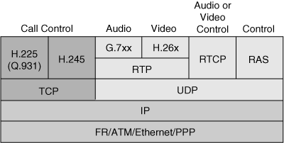
![]() Because of the time-sensitive nature of voice transport, UDP is the logical choice for carrying voice. However, voice conversation needs more information on a packet-by-packet basis than UDP offers. As shown in Figure 8-22, the Real-Time Transport Protocol (RTP), which runs on top of UDP, carries voice conversation (and video) between two IP endpoints.
Because of the time-sensitive nature of voice transport, UDP is the logical choice for carrying voice. However, voice conversation needs more information on a packet-by-packet basis than UDP offers. As shown in Figure 8-22, the Real-Time Transport Protocol (RTP), which runs on top of UDP, carries voice conversation (and video) between two IP endpoints.
![]() RTP provides the additional packet sequence and time-stamping information needed for voice conversation traffic. RTP uses the sequence information to determine whether the packets are arriving in order, and it uses the time-stamping information to determine the inter-arrival packet time (to determine the variation in delay, called jitter). This information is essential for high-quality VoIP conversations.
RTP provides the additional packet sequence and time-stamping information needed for voice conversation traffic. RTP uses the sequence information to determine whether the packets are arriving in order, and it uses the time-stamping information to determine the inter-arrival packet time (to determine the variation in delay, called jitter). This information is essential for high-quality VoIP conversations.
![]() Using RTP is important for real-time traffic; however, a few drawbacks exist. The IP/UDP/RTP packet headers are 20, 8, and 12 bytes, respectively, which results in a 40-byte header. This is twice as big as the compressed voice payload (when using the G.729 codec, discussed in the “Voice Coding Standards (Codecs)” section later in this chapter). This large header adds considerable overhead to voice traffic and reduces voice bandwidth efficiency.
Using RTP is important for real-time traffic; however, a few drawbacks exist. The IP/UDP/RTP packet headers are 20, 8, and 12 bytes, respectively, which results in a 40-byte header. This is twice as big as the compressed voice payload (when using the G.729 codec, discussed in the “Voice Coding Standards (Codecs)” section later in this chapter). This large header adds considerable overhead to voice traffic and reduces voice bandwidth efficiency.
| Note |
|
Call Control Functions with H.323
![]() A variety of standards and protocols can be used for call control. H.323 call control functions include signaling for call setup, capability exchange, signaling of commands and indications, and messages to open and describe the content of logical channels. The following H.323 signaling functions provide overall system control:
A variety of standards and protocols can be used for call control. H.323 call control functions include signaling for call setup, capability exchange, signaling of commands and indications, and messages to open and describe the content of logical channels. The following H.323 signaling functions provide overall system control:
-
 H.225 call signaling channel: Uses Q.931 to establish a connection between two terminals.
 -
 H.245 control channel: A reliable channel carrying control messages that govern voice operation, including capabilities exchange, opening and closing of logical channels, preference requests, flow control messages, and general commands and indications. Capabilities exchange is one of the fundamental capabilities in the ITU-U H.323 recommendation.
 -
 RAS signaling: Performs registration, admission, bandwidth change, status, and disengage procedures between endpoints and gatekeepers. The RAS protocol runs on top of UDP/IP and is used only if an H.323 gatekeeper is present.
 -
 Real-time Transport Control Protocol (RTCP): Provides a mechanism for hosts involved in an RTP session to exchange information about monitoring and controlling the session. RTCP monitors quality for such elements as packet counts, packet loss, and inter-arrival jitter.
![]() Figure 8-22 also shows these functions.
Figure 8-22 also shows these functions.
Call Control Functions with the Skinny Client Control Protocol
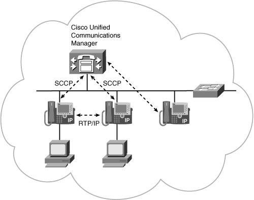
![]() By default, Cisco Unified Communications Manager uses SCCP to signal Cisco IP phones. SCCP is a client/server protocol; Cisco Unified Communications Manager is the server, and the IP phones are the clients. Examples of SCCP clients include the Cisco Unified IP Phone 7900 series phones, such as the Cisco Unified IP Phone 7960 series, the Cisco Unified IP Phone 7970 series, the Cisco Unified IP Phone 7985, and the 802.11b Cisco Unified Wireless IP Phone 7920.
By default, Cisco Unified Communications Manager uses SCCP to signal Cisco IP phones. SCCP is a client/server protocol; Cisco Unified Communications Manager is the server, and the IP phones are the clients. Examples of SCCP clients include the Cisco Unified IP Phone 7900 series phones, such as the Cisco Unified IP Phone 7960 series, the Cisco Unified IP Phone 7970 series, the Cisco Unified IP Phone 7985, and the 802.11b Cisco Unified Wireless IP Phone 7920.
![]() SCCP is a lightweight protocol that uses TCP/IP for efficient communication. Cisco Unified Communications Manager acts as a signaling proxy for the SCCP clients for call events received over other common protocols such as H.323, the session initiation protocol (SIP), and the Media Gateway Control Protocol (MGCP).
SCCP is a lightweight protocol that uses TCP/IP for efficient communication. Cisco Unified Communications Manager acts as a signaling proxy for the SCCP clients for call events received over other common protocols such as H.323, the session initiation protocol (SIP), and the Media Gateway Control Protocol (MGCP).
![]() SCCP clients register with Cisco Unified Communications Manager to receive their configuration information. After it registers, a Cisco IP phone receives notification of new incoming calls and can make outgoing calls. The SCCP protocol is used for VoIP call signaling and enhanced features such as the Message Waiting Indicator.
SCCP clients register with Cisco Unified Communications Manager to receive their configuration information. After it registers, a Cisco IP phone receives notification of new incoming calls and can make outgoing calls. The SCCP protocol is used for VoIP call signaling and enhanced features such as the Message Waiting Indicator.
![]() Media connections between devices involved in a call, including voice conversations, use RTP.
Media connections between devices involved in a call, including voice conversations, use RTP.
Call Control Functions with SIP
![]() SIP is defined in RFC 3261, SIP: Session Initiation Protocol. SIP performs the signaling and session management functions required in a packet telephony network. Signaling sends call information across network boundaries. Session management controls the attributes of an end-to-end call. SIP requests and responses establish communication among the various components in the network, ultimately creating a conference between two or more endpoints. A SIP network can include the following components:
SIP is defined in RFC 3261, SIP: Session Initiation Protocol. SIP performs the signaling and session management functions required in a packet telephony network. Signaling sends call information across network boundaries. Session management controls the attributes of an end-to-end call. SIP requests and responses establish communication among the various components in the network, ultimately creating a conference between two or more endpoints. A SIP network can include the following components:
-
 User agent (UA): SIP is a peer-to-peer protocol; the peers in a session are called UAs. A UA can act as both a UA client (UAC), which initiates calls, and a UA server (UAS), which receives calls. Whether a UA is acting as a UAC or a UAS is defined on a transaction-by-transaction basis; the UA initiating a call acts as a UAC when sending an invitation request, and as a UAS when receiving a goodbye request from the called party.
 A UAS (a server application) notifies the user when it receives a SIP request from a UAC; the UAS then responds on behalf of the user. Cisco Unified Communications Manager can act as both a UAS and a UAC; this functionality is known as a back-to-back UA.
 -
 SIP proxy server: A SIP proxy server works as an intermediate device that acts as both a server and a client for making requests on behalf of other clients. A SIP proxy server receives SIP requests from a client and interprets and, if necessary, rewrites specific parts of the request message before forwarding it on behalf of the client. Proxy servers provide functions such as authentication, authorization, network access control, call routing, reliable request retransmission, and security.
 -
 Redirect server: The redirect server is a UAS that provides the client with information about the next hop or hops that a message should take. For example, if an endpoint has moved, the redirect server might provide an alternative address. The client then contacts the next-hop server directly.
 -
 Registrar server: The registrar server processes requests from clients to register their current location; the registrar server puts the information it receives in the requests into the location service for the domain it handles. Redirect or proxy servers often also contain registrar servers.
![]() SIP integrates with other IP services, such as e-mail, web, voice mail, instant messaging, multiparty conferencing, and multimedia collaboration. When used with an IP infrastructure, SIP helps enable rich communications with numerous multivendor devices and media. SIP can set up individual voice or conference calls, videoconferences and point-to-point video-enabled calls, web collaboration and chat sessions, and instant-messaging sessions among any number of SIP-enabled endpoints.
SIP integrates with other IP services, such as e-mail, web, voice mail, instant messaging, multiparty conferencing, and multimedia collaboration. When used with an IP infrastructure, SIP helps enable rich communications with numerous multivendor devices and media. SIP can set up individual voice or conference calls, videoconferences and point-to-point video-enabled calls, web collaboration and chat sessions, and instant-messaging sessions among any number of SIP-enabled endpoints.
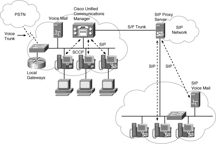
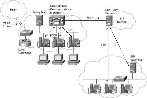
![]() Users in a SIP network are identified by unique SIP addresses, a type of uniform resource identifier (URI) called a SIP URI. The format of a SIP URI is similar to that of an e-mail address, typically containing a username and a hostname such as sip:nicholas@sipprovider.com, where sipprovider.com is Nicholas’s SIP service provider. Users register their assigned SIP addresses with a registrar server. The registrar server provides this information to the location service (which contains a list of bindings of addresses for contacts) upon request. The basic elements of a SIP system are UAs and proxy servers, as shown in Figure 8-24.
Users in a SIP network are identified by unique SIP addresses, a type of uniform resource identifier (URI) called a SIP URI. The format of a SIP URI is similar to that of an e-mail address, typically containing a username and a hostname such as sip:nicholas@sipprovider.com, where sipprovider.com is Nicholas’s SIP service provider. Users register their assigned SIP addresses with a registrar server. The registrar server provides this information to the location service (which contains a list of bindings of addresses for contacts) upon request. The basic elements of a SIP system are UAs and proxy servers, as shown in Figure 8-24.
![]() The SIP UA software is implemented in end-user devices and server components to manage the SIP connection. SIP UAs include endpoints such as IP phones, SIP media gateways, conferencing servers, and messaging systems.
The SIP UA software is implemented in end-user devices and server components to manage the SIP connection. SIP UAs include endpoints such as IP phones, SIP media gateways, conferencing servers, and messaging systems.
![]() SIP UAs communicate with a SIP proxy server. SIP proxy servers, such as the Cisco SIP Proxy Server application, route SIP requests from UAs to their appropriate destinations. SIP proxy servers are typically collocated with a SIP registrar, which maintains a list of contacts for specific users within a specific IP domain.
SIP UAs communicate with a SIP proxy server. SIP proxy servers, such as the Cisco SIP Proxy Server application, route SIP requests from UAs to their appropriate destinations. SIP proxy servers are typically collocated with a SIP registrar, which maintains a list of contacts for specific users within a specific IP domain.
![]() SIP proxy servers also provide integrated communications with Cisco Unified Communications Manager and enterprise voice gateways. SIP-compliant devices such as IP phones can register directly with Cisco Unified Communications Manager.
SIP proxy servers also provide integrated communications with Cisco Unified Communications Manager and enterprise voice gateways. SIP-compliant devices such as IP phones can register directly with Cisco Unified Communications Manager.
| Note |
|
Call Control Functions with MGCP
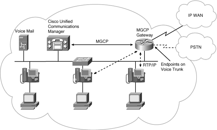
![]() MGCP is a client/server protocol defined in an informational (nonstandard) IETF document, RFC 3435, Media Gateway Control Protocol (MGCP) Version 1.0. The components of MGCP are shown in Figure 8-25.
MGCP is a client/server protocol defined in an informational (nonstandard) IETF document, RFC 3435, Media Gateway Control Protocol (MGCP) Version 1.0. The components of MGCP are shown in Figure 8-25.
![]() Endpoints communicate over connections. A gateway handles translation between audio signals on the endpoints and the packet network. The MGCP call agent knows and controls the state of each individual port on the gateway. MGCP allows complete control of the dial plan from the call agent, including per-port control of connections to the PSTN, legacy PBX, voice-mail systems, plain old telephone service phones, and so forth. The call agent and the gateway communicate using a series of plaintext commands sent over UDP port 2427.
Endpoints communicate over connections. A gateway handles translation between audio signals on the endpoints and the packet network. The MGCP call agent knows and controls the state of each individual port on the gateway. MGCP allows complete control of the dial plan from the call agent, including per-port control of connections to the PSTN, legacy PBX, voice-mail systems, plain old telephone service phones, and so forth. The call agent and the gateway communicate using a series of plaintext commands sent over UDP port 2427.
![]() An endpoint is a source for call data (using RTP/UDP/IP) that is flowing through the gateway. Examples of endpoints are analog voice ports and channels on a digital trunk on the physical interface between the PSTN and the gateway. Other types of endpoints include logical endpoints.
An endpoint is a source for call data (using RTP/UDP/IP) that is flowing through the gateway. Examples of endpoints are analog voice ports and channels on a digital trunk on the physical interface between the PSTN and the gateway. Other types of endpoints include logical endpoints.
![]() In an MGCP call, a call agent creates a connection either between an endpoint and the packet network or between two endpoints. When a connection is made to an endpoint, the gateway assigns a connection identifier for that connection.
In an MGCP call, a call agent creates a connection either between an endpoint and the packet network or between two endpoints. When a connection is made to an endpoint, the gateway assigns a connection identifier for that connection.

0 comments
Post a Comment