![]() This chapter describes how converged voice networks can run the same applications as a telephony network, but in a more cost-effective and scalable manner. It describes voice and data networking concepts and introduces VoIP and IP telephony.
This chapter describes how converged voice networks can run the same applications as a telephony network, but in a more cost-effective and scalable manner. It describes voice and data networking concepts and introduces VoIP and IP telephony.
![]() This chapter discusses voice quality issues, coding and compression standards, and bandwidth considerations and requirements when voice traffic is present on a network. Quality of service (QoS) mechanisms available for voice are described, and voice traffic engineering concepts are examined.
This chapter discusses voice quality issues, coding and compression standards, and bandwidth considerations and requirements when voice traffic is present on a network. Quality of service (QoS) mechanisms available for voice are described, and voice traffic engineering concepts are examined.
 Traditional Voice Architectures and Features
![]() This section introduces the traditional telephony infrastructure and explains its major components. It describes analog and digital signaling and the process to convert between the two. PBX and Public Switched Telephone Network (PSTN) switches are described and contrasted. The telephone infrastructure and connections between telephony devices are examined. Telephony signaling mechanisms are described, and PSTN numbering plans are explained.
This section introduces the traditional telephony infrastructure and explains its major components. It describes analog and digital signaling and the process to convert between the two. PBX and Public Switched Telephone Network (PSTN) switches are described and contrasted. The telephone infrastructure and connections between telephony devices are examined. Telephony signaling mechanisms are described, and PSTN numbering plans are explained.
| Note |
|
 Analog and Digital Signaling
![]() The human voice generates sound waves; a telephone converts the sound waves into analog signals. However, analog transmission is not particularly efficient. Analog signals must be amplified when they become weak from transmission loss as they travel. However, amplification of analog signals also amplifies noise.
The human voice generates sound waves; a telephone converts the sound waves into analog signals. However, analog transmission is not particularly efficient. Analog signals must be amplified when they become weak from transmission loss as they travel. However, amplification of analog signals also amplifies noise.
![]() The PSTN is a collection of interconnected voice-oriented public telephone networks, both commercial and government-owned. The PSTN today consists almost entirely of digital technology, except for the final link from the central (local) telephone office to the user. To obtain clear voice connections, the PSTN switches convert analog speech to a digital format and send it over the digital network. At the other end of the connection, the digital signal is converted back to analog and to the normal sound waves that the ear picks up. Digital signals are more immune to noise, and the digital network does not induce any additional noise when amplifying signals.
The PSTN is a collection of interconnected voice-oriented public telephone networks, both commercial and government-owned. The PSTN today consists almost entirely of digital technology, except for the final link from the central (local) telephone office to the user. To obtain clear voice connections, the PSTN switches convert analog speech to a digital format and send it over the digital network. At the other end of the connection, the digital signal is converted back to analog and to the normal sound waves that the ear picks up. Digital signals are more immune to noise, and the digital network does not induce any additional noise when amplifying signals.
![]() Signals in digital networks are transmitted over great distances and are coded, regenerated, and decoded without degradation of quality. Repeaters amplify the signal, restore it to its original condition, and send this clean signal to the next network destination.
Signals in digital networks are transmitted over great distances and are coded, regenerated, and decoded without degradation of quality. Repeaters amplify the signal, restore it to its original condition, and send this clean signal to the next network destination.
The Analog-to-Digital Process
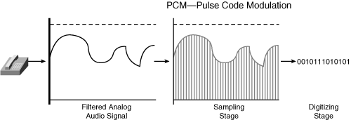
![]() Pulse code modulation (PCM) is the process of digitizing analog voice signals. Several steps are involved in converting an analog signal into PCM digital format, as shown in Figure 8-1 and described here:
Pulse code modulation (PCM) is the process of digitizing analog voice signals. Several steps are involved in converting an analog signal into PCM digital format, as shown in Figure 8-1 and described here:
-
 Filtering: Filters out the signal’s nonspeech frequency components. Most of the energy of spoken language ranges from approximately 300 hertz (Hz) to 3400 Hz; this is the 3100 Hz bandwidth, or range, for standard speech. Analog waveforms are put through a voice frequency filter to filter out anything greater than 4000 Hz.
 -
 Sampling: Samples the filtered input signal at a constant frequency, using a process called pulse amplitude modulation (PAM). This step uses the original analog signal to modulate the amplitude of a pulse train that has a constant amplitude and frequency. The filtered analog signal is sampled at twice the highest frequency of the analog input signal (4000 Hz); therefore, the signal is sampled 8000 times per second, or every 125 microseconds (Mu-sec).
 -
 Digitizing: Digitizes the samples in preparation for transmission over a telephony network; this is the PCM process. PCM takes the PAM process one step further by encoding each analog sample using binary code words. An analog-to-digital converter is required on the source side, and a digital-to-analog converter is required on the destination side.
![]() The digitizing process is further divided into the following steps:
The digitizing process is further divided into the following steps:
-
 Quantization and coding: A process that converts each analog sample value into a discrete value to which a unique digital code word can be assigned. As the input signal sample enters the quantization phase, it is assigned to a quantization interval. All quantization intervals are equally spaced throughout the dynamic range of the input analog signal. Each quantization interval is assigned a discrete binary code word value. The standard word size used is 8 bits, enabling 256 possible quantization intervals.
 -
 Companding: The process of first compressing an analog signal at the source and then expanding (decompressing) this signal back to its original size when it reaches its destination. (Combining the terms compressing and expanding creates the term companding.) During the companding process, input analog signal samples are compressed into logarithmic segments, and each segment is quantified and coded using uniform quantization. The compression process is logarithmic, meaning that the compression increases as the sample signals increase. In other words, larger sample signals are compressed more than smaller sample signals, thereby causing the quantization noise to increase as the sample signal increases. This results in a more accurate value for smaller-amplitude signals and a uniform signal-to-noise ratio across the input range.
 Two basic variations of logarithmic companding are commonly used: The a-law companding standard is used in Europe, and Mu-law is used in North America and Japan. The methods are similar—they both use logarithmic compression to achieve linear approximations in 8-bit words—but they are not compatible.
Time-Division Multiplexing in PSTN
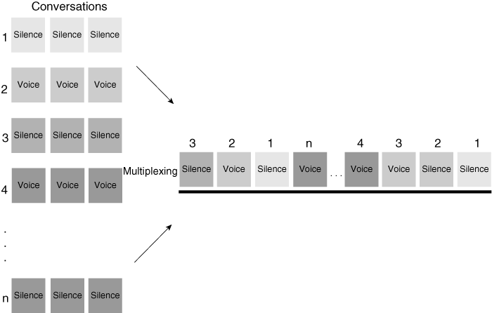
![]() Time-division multiplexing (TDM) is used in networks that are commonly deployed by telephone companies, including the PSTN. As illustrated in Figure 8-2, TDM is a digital transmission technique for simultaneously carrying multiple signals over a single trunk line by interleaving octets from each signal into different time slots.
Time-division multiplexing (TDM) is used in networks that are commonly deployed by telephone companies, including the PSTN. As illustrated in Figure 8-2, TDM is a digital transmission technique for simultaneously carrying multiple signals over a single trunk line by interleaving octets from each signal into different time slots.
![]() The PSTN allocates a dedicated 64-kbps digital channel for each call. Although TDM cannot allocate bandwidth on demand as packet switching can, TDM’s fixed-bandwidth allocation ensures that a channel is never blocked because of competition for bandwidth resources on another channel, and that performance does not degrade because of network congestion.
The PSTN allocates a dedicated 64-kbps digital channel for each call. Although TDM cannot allocate bandwidth on demand as packet switching can, TDM’s fixed-bandwidth allocation ensures that a channel is never blocked because of competition for bandwidth resources on another channel, and that performance does not degrade because of network congestion.
![]() With time slot allocation, the number of simultaneous calls cannot exceed the number of TDM slots in the trunk. One call always allocates one TDM slot, regardless of whether silence or speech is transmitted. Time slot allocation ensures that connections always have access to a trunk, thereby resulting in low delay. However, because of the allocation method, the overall trunk utilization, also known as trunk efficiency, becomes relatively low.
With time slot allocation, the number of simultaneous calls cannot exceed the number of TDM slots in the trunk. One call always allocates one TDM slot, regardless of whether silence or speech is transmitted. Time slot allocation ensures that connections always have access to a trunk, thereby resulting in low delay. However, because of the allocation method, the overall trunk utilization, also known as trunk efficiency, becomes relatively low.
![]() The low trunk efficiency of circuit-switched networks is a major driver for the migration to unified packet-switched networks in which bandwidth is consumed only when there is traffic.
The low trunk efficiency of circuit-switched networks is a major driver for the migration to unified packet-switched networks in which bandwidth is consumed only when there is traffic.
 PBXs and the PSTN
![]() This section introduces PBX and PSTN switches and networks.
This section introduces PBX and PSTN switches and networks.
Differences Between a PBX and a PSTN Switch
![]() As shown in Table 8-1, PBXs and PSTN switches share many similarities, but they also have many differences.
As shown in Table 8-1, PBXs and PSTN switches share many similarities, but they also have many differences.
|
|
|
|---|---|
|
|
|
|
|
|
|
|
|
|
|
|
|
|
|
|
|
|
![]() Both the PBX and PSTN switch systems use 64-kbps circuits; however, the scale is very different. A PSTN switch can support hundreds of thousands of telephones, whereas a PBX can support only several thousand.
Both the PBX and PSTN switch systems use 64-kbps circuits; however, the scale is very different. A PSTN switch can support hundreds of thousands of telephones, whereas a PBX can support only several thousand.
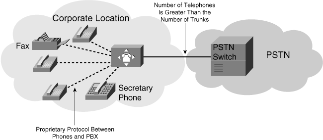
![]() PBX vendors often create proprietary protocols to enable their PBXs to intercommunicate and transparently carry additional features through their voice network. In addition, only the vendor’s telephones can be connected to its PBX. This forces enterprise networks to consolidate to one brand of PBX, and the enterprise business customer is restricted to one vendor.
PBX vendors often create proprietary protocols to enable their PBXs to intercommunicate and transparently carry additional features through their voice network. In addition, only the vendor’s telephones can be connected to its PBX. This forces enterprise networks to consolidate to one brand of PBX, and the enterprise business customer is restricted to one vendor.
| Note |
|
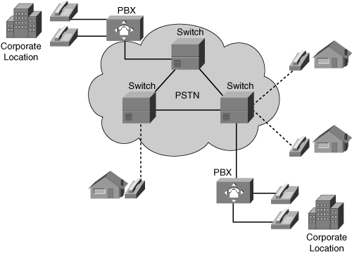
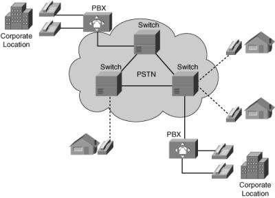
![]() Figure 8-3 illustrates the location of and communication between the PSTN and PBXs. PSTN switches connect residential and business users, but PBXs are mainly used for business purposes. PBXs are typically found at corporate locations, whereas PSTN switches are used to build the PSTN network and are located in central offices (CO).
Figure 8-3 illustrates the location of and communication between the PSTN and PBXs. PSTN switches connect residential and business users, but PBXs are mainly used for business purposes. PBXs are typically found at corporate locations, whereas PSTN switches are used to build the PSTN network and are located in central offices (CO).
PBX Features
![]() A PBX is a business telephone system that provides business features such as call hold, call transfer, call forward, follow-me, call park, conference calls, music on hold, call history, and voice mail. Most of these features are not available in traditional PSTN switches.
A PBX is a business telephone system that provides business features such as call hold, call transfer, call forward, follow-me, call park, conference calls, music on hold, call history, and voice mail. Most of these features are not available in traditional PSTN switches.
![]() A PBX switch often connects to the PSTN through one or more T1 or E1 digital circuits. A PBX supports end-to-end digital transmission, employs PCM switching technology, and supports both analog and digital proprietary telephones.
A PBX switch often connects to the PSTN through one or more T1 or E1 digital circuits. A PBX supports end-to-end digital transmission, employs PCM switching technology, and supports both analog and digital proprietary telephones.
![]() Recall from Chapter 5, “Designing Remote Connectivity,” that the United States, Canada, and Japan use T1. A T1 trunk can carry 24 fixed 64-kbps channels for either voice or data, using PCM signals and TDM, plus additional bits for framing, resulting in an aggregate carrying capacity of 1.544 megabits per second (Mbps). T1 lines originally used copper wire but now also include optical and wireless media.
Recall from Chapter 5, “Designing Remote Connectivity,” that the United States, Canada, and Japan use T1. A T1 trunk can carry 24 fixed 64-kbps channels for either voice or data, using PCM signals and TDM, plus additional bits for framing, resulting in an aggregate carrying capacity of 1.544 megabits per second (Mbps). T1 lines originally used copper wire but now also include optical and wireless media.
![]() In Europe, the trunk used to carry a digital transmission is an E1. An E1 trunk can carry up to 31 fixed 64-kbps channels for data and signaling, with another 64-kbps channel reserved for framing, giving an aggregate carrying capacity of 2.048 Mbps.
In Europe, the trunk used to carry a digital transmission is an E1. An E1 trunk can carry up to 31 fixed 64-kbps channels for data and signaling, with another 64-kbps channel reserved for framing, giving an aggregate carrying capacity of 2.048 Mbps.
![]() PBXs support end-to-end digital transmission, use PCM switching technology, and support both analog and digital proprietary telephones. A local PBX provides several advantages for an enterprise:
PBXs support end-to-end digital transmission, use PCM switching technology, and support both analog and digital proprietary telephones. A local PBX provides several advantages for an enterprise:
-
 Local calls between telephones within the PBX or group of PBXs are free of charge.
 -
 Most PBX telephone system users do not call externally, through the T1 or E1 circuits, at the same time. Therefore, companies with a PBX only need the number of external lines to the PSTN to equal the maximum possible number of simultaneous calls, resulting in PSTN cost savings.
 -
 When adding a new user, changing a voice feature, or moving a user to a different location, there is no need to contact the PSTN carrier; the local administrator can reconfigure the PBX.
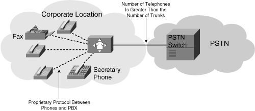
![]() However, the PBX adds another level of complexity: The enterprise customer must configure and maintain the PBX. Figure 8-4 illustrates a typical enterprise telephone network that has proprietary telephones connected to the PBX and a trunk between the PBX and the PSTN network.
However, the PBX adds another level of complexity: The enterprise customer must configure and maintain the PBX. Figure 8-4 illustrates a typical enterprise telephone network that has proprietary telephones connected to the PBX and a trunk between the PBX and the PSTN network.
PSTN Switches
![]() The PSTN appears to be a single large network with telephone lines connected. In reality, the PSTN is composed of circuits, switches, signaling devices, and telephones. Many different companies own and operate different systems within the PSTN.
The PSTN appears to be a single large network with telephone lines connected. In reality, the PSTN is composed of circuits, switches, signaling devices, and telephones. Many different companies own and operate different systems within the PSTN.
PSTN Features
![]() A PSTN switch’s primary role is to connect the calling and called parties. If the two parties are physically connected to the same PSTN switch, the call remains local; otherwise, the PSTN switch forwards the call to the destination switch that owns the called party.
A PSTN switch’s primary role is to connect the calling and called parties. If the two parties are physically connected to the same PSTN switch, the call remains local; otherwise, the PSTN switch forwards the call to the destination switch that owns the called party.
![]() PSTN switches interconnect business PBXs and public and private telephones. Large PSTN switches are located at COs, which provide circuits throughout the telephony network. PSTN switches are deployed in hierarchies to provide resiliency and redundancy to the PSTN network and avoid a single point of failure.
PSTN switches interconnect business PBXs and public and private telephones. Large PSTN switches are located at COs, which provide circuits throughout the telephony network. PSTN switches are deployed in hierarchies to provide resiliency and redundancy to the PSTN network and avoid a single point of failure.
![]() PSTN signaling traditionally supported only basic features such as caller ID and direct inward dialing. Modern PSTN switches now support, on a fee basis, many traditional PBX services, including conferencing, forwarding, call holding, and voice mail.
PSTN signaling traditionally supported only basic features such as caller ID and direct inward dialing. Modern PSTN switches now support, on a fee basis, many traditional PBX services, including conferencing, forwarding, call holding, and voice mail.
PSTN Services
![]() Modern PSTN service providers offer competitive services to differentiate themselves and generate additional revenue. These PSTN services include the following:
Modern PSTN service providers offer competitive services to differentiate themselves and generate additional revenue. These PSTN services include the following:
-
 Centrex: Centrex is a set of specialized business solutions (primarily, but not exclusively, for voice service) in which the service provider owns and operates the equipment that provides both call control and service logic functions; therefore, the equipment is located on the service provider’s premises.
 -
 Voice virtual private networks (VPN): Voice VPNs interconnect corporate voice traffic among multiple locations over the PSTN. PBXs are connected to the PSTN instead of directly over tie trunks. The PSTN service provider provides call routing among locations, and all PBX features are carried transparently across the PSTN.
 -
 Voice mail: Voice mail is an optional service that lets PSTN customers divert their incoming PSTN calls to a voice mailbox when they are unable to answer their telephones, such as when the line is busy or they are unavailable. Alternatively, all calls can be diverted to the voice mailbox.
 -
 Call center: A call center is a place of doing business by telephone, combined with a centralized database that uses an automatic call distribution (ACD) system. Call centers require live agents to accept and handle calls.
 -
 Interactive voice response: Interactive voice response (IVR) systems allow callers to exchange information over the telephone without an intermediary live agent. The caller and the IVR system interact using a combination of spoken messages and dual-tone multifrequency (DTMF) touch-tone telephone pad buttons.
 Local Loops, Trunks, and Interswitch Communications
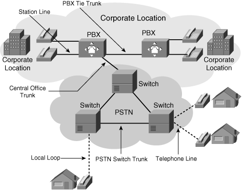
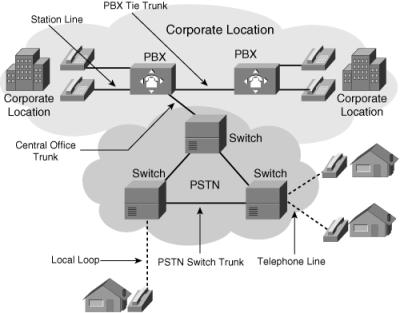
![]() Figure 8-5 illustrates a typical telephone infrastructure and connections between telephony devices.
Figure 8-5 illustrates a typical telephone infrastructure and connections between telephony devices.
![]() The telephone infrastructure starts with a simple pair of copper wires running to the end user’s home or business. This physical cabling is known as a local loop or telephone line; the local loop physically connects the home telephone to the CO PSTN switch. Similarly, the connection between an enterprise PBX and its telephones is called the station line.
The telephone infrastructure starts with a simple pair of copper wires running to the end user’s home or business. This physical cabling is known as a local loop or telephone line; the local loop physically connects the home telephone to the CO PSTN switch. Similarly, the connection between an enterprise PBX and its telephones is called the station line.
![]() A trunk is a communication path between two telephony systems. Available trunk types, shown in Figure 8-5, include the following:
A trunk is a communication path between two telephony systems. Available trunk types, shown in Figure 8-5, include the following:
-
 Tie trunk: Connects enterprise PBXs without connecting to the PSTN (in other words, not connecting to a phone company’s CO). Tie trunks are used, for example, to connect PBXs in different cities so that the enterprise can use the PBX rather than the PSTN for intercity calls between offices and, as a result, save on long-distance toll charges. A connection to the PSTN—via a CO trunk—is still required for off-net calls (to nonoffice numbers).
 -
 CO trunk: Connects CO switches to enterprise PBXs. Enterprises connect their PBXs to the PSTN with PBX-to-CO trunks. The telephone service provider is responsible for running CO-to-PBX trunks between its CO and enterprise PBXs; from a service provider point of view, these are lines or business lines.
 -
 PSTN switch trunk: Interconnects CO switches; also called interoffice trunks.
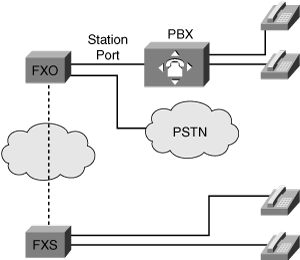
![]() As shown in Figure 8-6, another type of trunk, foreign exchange (FX) trunks, are analog interfaces used to interconnect a PBX to telephones, other PBXs, or to the PSTN. FX trunks save on long-distance toll calls; the dial tone from a different toll region is produced via the FX trunk at a reduced tariff.
As shown in Figure 8-6, another type of trunk, foreign exchange (FX) trunks, are analog interfaces used to interconnect a PBX to telephones, other PBXs, or to the PSTN. FX trunks save on long-distance toll calls; the dial tone from a different toll region is produced via the FX trunk at a reduced tariff.
![]() Two types of FX trunk interfaces exist:
Two types of FX trunk interfaces exist:
-
 Foreign Exchange Office (FXO): This interface emulates a telephone. It creates an analog connection to a PSTN CO or to a station interface on a PBX. The FXO interface sits on the PSTN or PBX end of the connection and plugs directly into the line side of the PSTN or PBX so that the PSTN or PBX thinks the FXO interface is a telephone. The FXO interface provides either pulse or DTMF digits for outbound dialing. The PBX or PSTN notifies the FXO of an incoming call by sending ringing voltage to the FXO. Likewise, the FXO answers a call by closing the loop to allow current flow. After current is flowing, the FXO interface transports the signal to the Foreign Exchange Station (FXS).
 -
 FXS: This interface emulates a PBX. It connects directly to a standard telephone, fax machine, or similar device and supplies line power, ring voltage, and dial tone to the end device. An example of where an FXS is used to emulate a PBX is in locations where there are not physical lines for every telephone.
 Telephony Signaling
![]() In a telephony system, a signaling mechanism is required for establishing and disconnecting telephone communications.
In a telephony system, a signaling mechanism is required for establishing and disconnecting telephone communications.
Telephony Signaling Types
![]() The following forms of signaling are used when a telephone call is placed via a PBX:
The following forms of signaling are used when a telephone call is placed via a PBX:
-
 Between the telephone and PBX
 -
 Between the PBX and PSTN switch
 -
 Between the PSTN switches
 -
 Between two PBXs
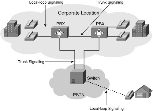
![]() At a high level, there are two signaling realms, as shown in Figure 8-7:
At a high level, there are two signaling realms, as shown in Figure 8-7:
-
 Local-loop signaling: Between a PSTN or PBX switch and a subscriber (telephone)
 -
 Trunk signaling: Between PSTN switches, between a PSTN switch and a PBX, or between PBX switches
![]() Simple signaling examples include the ringing of the telephone, a dial tone, and a ring-back tone. Following are the three basic categories of signals commonly used in telephone networks:
Simple signaling examples include the ringing of the telephone, a dial tone, and a ring-back tone. Following are the three basic categories of signals commonly used in telephone networks:
-
 Supervision signaling: Typically characterized as on-hook, off-hook, and ringing, supervision signaling alerts the CO switch to the state of the telephone on each local loop. Supervision signaling is used, for example, to initiate a telephone call request on a line or trunk and to hold or release an established connection.
 -
 Address signaling: Used to pass dialed digits (pulse or DTMF) to a PBX or PSTN switch. These dialed digits provide the switch with a connection path to another telephone or customer premises equipment.
 -
 Informational signaling: Includes dial tone, busy tone, reorder tone, and tones indicating that a receiver is off-hook or that no such number exists, such as those used with call progress indicators.
![]() For a telephone call to take place, all three types of signaling occur.
For a telephone call to take place, all three types of signaling occur.
Analog Telephony Signaling
![]() The most common methods of analog local-loop signaling are loop start and ground start. The most common analog trunk signaling method is E&M (derived from a combination of recEive and transMit, and sometimes known as Ear and Mouth). These methods are described as follows:
The most common methods of analog local-loop signaling are loop start and ground start. The most common analog trunk signaling method is E&M (derived from a combination of recEive and transMit, and sometimes known as Ear and Mouth). These methods are described as follows:
-
 Loop start: Loop start is the simplest and least intelligent signaling protocol, and the most common form of local-loop signaling. It provides a way to indicate on-hook and off-hook conditions in a voice network. The creation of the electrical loop initiates a call (off-hook), and the opening of the loop terminates the call (on-hook). This type of signaling is not common for PBX signaling because it has a significant drawback in which glare—what the telephone industry calls collisions—can occur. Glare occurs when two endpoints try to seize the line at the same time, resulting in the two callers connecting unexpectedly. Because business callers use telephones regularly and the possibility of glare is high, loop-start signaling is acceptable only for residential use.
 -
 Ground start: Also called reverse battery, ground start is a modification of loop start that provides positive recognition of connects and disconnects (off-hook and on-hook). It uses current-detection mechanisms at each end of the trunk, thereby enabling PBXs to agree which end will seize the trunk before actually doing so, minimizing the effect of glare. Ground start is preferred when there is a high volume of calls; therefore, PBXs typically use this type of signaling.
 -
 E&M: E&M is a common trunk signaling technique used between PBXs. In E&M, voice is transmitted over either two- or four-wire circuits, with five types of E&M signaling (Types I, II, III, IV, and V). E&M uses separate paths (or leads) for voice and signaling. The M (Mouth) lead sends the signal, and the E (Ear) lead receives the signal.
Digital Telephony Signaling
![]() On PSTN switches, analog signaling is usually provided through current flow in closed electrical circuits, and digital signaling is provided through channel associated signaling (CAS) or common channel signaling (CCS).
On PSTN switches, analog signaling is usually provided through current flow in closed electrical circuits, and digital signaling is provided through channel associated signaling (CAS) or common channel signaling (CCS).
CAS
![]() Many varieties of CAS exist, and they operate over various analog and digital facilities.
Many varieties of CAS exist, and they operate over various analog and digital facilities.
![]() Examples of CAS signaling include the following:
Examples of CAS signaling include the following:
-
 R1 signaling (on T1 facilities): Used in North America.
 -
 R2 signaling (on E1 facilities): Used in Europe, Latin America, Australia, and Asia.
 -
 DTMF signals: DTMF signals are the “pulses” used within the call path.
CCS
![]() Modern telecommunication networks require more efficient means of signaling, so they are moving toward CCS systems. CCS can have faster connect times than CAS, and it offers the possibility of a number of additional services.
Modern telecommunication networks require more efficient means of signaling, so they are moving toward CCS systems. CCS can have faster connect times than CAS, and it offers the possibility of a number of additional services.
![]() Examples of CCS signaling include the following:
Examples of CCS signaling include the following:
-
 DPNSS
DPNSS -
 Integrated Services Digital Network (ISDN)
 -
 QSIG
QSIG -
 Signaling System 7 (SS7)
![]() The following sections further describe these types of CCS signaling.
The following sections further describe these types of CCS signaling.
DPNSS
![]() DPNSS is an industry-standard interface defined between a PBX and an access network. DPNSS expands the facilities normally available only between extensions on a single PBX to all extensions on PBXs connected in a private network.
DPNSS is an industry-standard interface defined between a PBX and an access network. DPNSS expands the facilities normally available only between extensions on a single PBX to all extensions on PBXs connected in a private network.
ISDN
![]() ISDN provides digital telephony and data transport services. ISDN involves the digitalization of the telephone network, permitting voice, data, text, graphics, music, video, and other source material to be transmitted on the same facility. For example, ISDN enables PBXs to connect over the PSTN and to create voice VPNs by delivering PBX signaling over the network to distant PBXs.
ISDN provides digital telephony and data transport services. ISDN involves the digitalization of the telephone network, permitting voice, data, text, graphics, music, video, and other source material to be transmitted on the same facility. For example, ISDN enables PBXs to connect over the PSTN and to create voice VPNs by delivering PBX signaling over the network to distant PBXs.
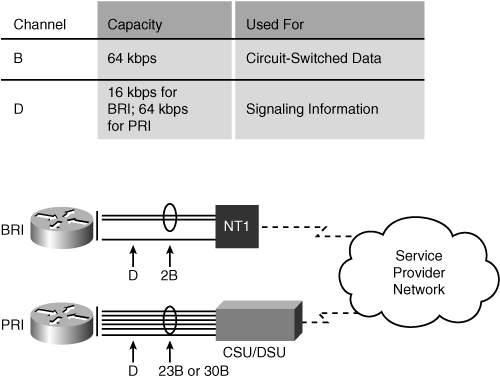
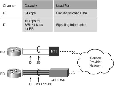
![]() Following are the two ISDN access methods, as illustrated in Figure 8-8:
Following are the two ISDN access methods, as illustrated in Figure 8-8:
-
 ISDN Basic Rate Interface (BRI): Offers two bearer (B) channels and one delta (D) channel (2B+D). The BRI B channel operates at 64 kbps and carries user data and voice. The BRI D channel operates at 16 kbps and carries both control and signaling information. BRI is typically used for residential and small office/home office applications.
 -
 ISDN Primary Rate Interface (PRI): Designed to use T1 or E1 circuits, PRI offers 23 B channels and one D channel (23B+D) in North America and 30 B channels and one D channel (30B+D) in Europe. The PRI B channels operate at 64 kbps and carry user data and voice. The PRI D channel also operates at 64 kbps and carries both control and signaling information. PRI is typically used for enterprise business and voice applications.
QSIG Digital Signaling
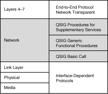
![]() Figure 8-9 illustrates QSIG. QSIG is a peer-to-peer signaling system used in corporate voice networking to provide standardized inter-PBX communications. It is a standards-based mechanism that provides transparent transportation of PBX features across a network.
Figure 8-9 illustrates QSIG. QSIG is a peer-to-peer signaling system used in corporate voice networking to provide standardized inter-PBX communications. It is a standards-based mechanism that provides transparent transportation of PBX features across a network.
![]() QSIG features include the following:
QSIG features include the following:
-
 Standards-based protocol that enables interconnection of multivendor equipment
 -
 Enables inter-PBX basic services, generic feature transparency between PBXs, and supplementary services
 -
 Interoperability with public and private ISDN
 -
 Operable in any network configuration and compatible with many PBX-type interfaces
 -
 No restrictions on private numbering plans
SS7 Digital Signaling
![]() SS7 is an international signaling standard within the PSTN. SS7 defines the architecture, network elements, interfaces, protocols, and management procedures for a network that transports control information between PSTN switches. SS7 works between PSTN switches and replaces per-trunk in-band signaling.
SS7 is an international signaling standard within the PSTN. SS7 defines the architecture, network elements, interfaces, protocols, and management procedures for a network that transports control information between PSTN switches. SS7 works between PSTN switches and replaces per-trunk in-band signaling.
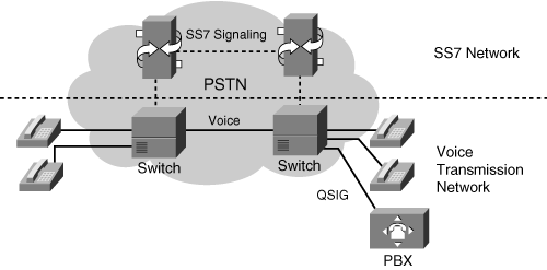
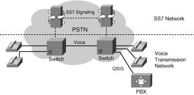
![]() As shown in Figure 8-10, a separate data network within the PSTN implements SS7. SS7 provides call setup and teardown, network management, fault resolution, and traffic management services. The SS7 network is solely for network control. Out-of-band signaling via SS7 provides numerous benefits for internetworking design, including reduced call setup time, bearer capability, and other progress indicators.
As shown in Figure 8-10, a separate data network within the PSTN implements SS7. SS7 provides call setup and teardown, network management, fault resolution, and traffic management services. The SS7 network is solely for network control. Out-of-band signaling via SS7 provides numerous benefits for internetworking design, including reduced call setup time, bearer capability, and other progress indicators.
 PSTN Numbering Plans
![]() PSTN numbering plans are the foundation for routing voice calls through the PSTN network.
PSTN numbering plans are the foundation for routing voice calls through the PSTN network.
International Numbering Plans
![]() For any telephone network to function, a unique address must identify each telephone. Voice addressing relies on a combination of international and national standards, local telephone company practices, and internal customer-specific codes. The International Telecommunications Union Telecommunication Standardization Sector (ITU-T) recommendation E.164 defines the international numbering plan. Each country’s national numbering plan must conform to the E.164 recommendation and work in conjunction with the international numbering plan in a hierarchical fashion. PSTN service providers must ensure that their numbering plan aligns with the E.164 recommendation and that their customers’ networks conform.
For any telephone network to function, a unique address must identify each telephone. Voice addressing relies on a combination of international and national standards, local telephone company practices, and internal customer-specific codes. The International Telecommunications Union Telecommunication Standardization Sector (ITU-T) recommendation E.164 defines the international numbering plan. Each country’s national numbering plan must conform to the E.164 recommendation and work in conjunction with the international numbering plan in a hierarchical fashion. PSTN service providers must ensure that their numbering plan aligns with the E.164 recommendation and that their customers’ networks conform.
Call Routing
![]() Call routing is closely related to the numbering plan and signaling. Basic routing allows the source telephone to establish a call to the destination telephone. However, most routing is more sophisticated: It enables subscribers to select services or divert calls from one subscriber to another. Routing results from establishing a set of tables or rules within each switch. As each call arrives, the path to the desired destination and the type of services available derive from these tables or rules.
Call routing is closely related to the numbering plan and signaling. Basic routing allows the source telephone to establish a call to the destination telephone. However, most routing is more sophisticated: It enables subscribers to select services or divert calls from one subscriber to another. Routing results from establishing a set of tables or rules within each switch. As each call arrives, the path to the desired destination and the type of services available derive from these tables or rules.
Numbering Plans
![]() Specific numbers within the dialed digits indicate special codes. An international prefix is the code dialed before an international number. In most nations, the international prefix is 00. In some nations in Asia, it is 001 (in some cases, alternative codes are available to select a particular international carrier). In North America, the international prefix is 011 (or 01 for special call processing—collect, person-to-person, calling card, and so on).
Specific numbers within the dialed digits indicate special codes. An international prefix is the code dialed before an international number. In most nations, the international prefix is 00. In some nations in Asia, it is 001 (in some cases, alternative codes are available to select a particular international carrier). In North America, the international prefix is 011 (or 01 for special call processing—collect, person-to-person, calling card, and so on).
![]() A country code is used to reach a particular telephone system (or special service) for each nation. The initial digit in the country code is a zone, which usually relates to a general geographic region (for example, zone 5 is South America and Latin America). Table 8-2 provides examples of country codes and zones.
A country code is used to reach a particular telephone system (or special service) for each nation. The initial digit in the country code is a zone, which usually relates to a general geographic region (for example, zone 5 is South America and Latin America). Table 8-2 provides examples of country codes and zones.
|
|
|
|
|---|---|---|
|
|
|
|
|
|
|
|
|
|
|
|
|
|
|
|
|
|
|
|
|
|
|
|
|
|
|
|
|
|
|
|
|
|
|
|
|
|
|
|
|
|
|
|
|
|
|
|
|
|
| |
|
|
|
|
|
|
|
|
|
|
|
|
|
|
|
|
|
|
|
|
|
|
|
|
|
|
|
|
|
|
|
|
|
|
|
|
|
|
|
|
|
|
|
|
![]() A trunk prefix is the initial digit or digits dialed before the area code (if necessary) and the subscriber number when making a domestic call. The trunk prefix in North America is 1; it is 0 in most other places.
A trunk prefix is the initial digit or digits dialed before the area code (if necessary) and the subscriber number when making a domestic call. The trunk prefix in North America is 1; it is 0 in most other places.
North American Numbering Plan
![]() The North American Numbering Plan (NANP), as illustrated in Figure 8-11, is an example of a PSTN numbering plan. It conforms to the ITU-T recommendation E.164. NANP numbers are ten digits in length and occur in the following format: NXX-NXX-XXXX, where N is any digit 2–9 and X is any digit 0–9. The first three digits identify the numbering plan area and are commonly called the area code. The next three digits are called the CO code; other names for these three digits are prefix, exchange, or simply NXX. The final four digits are called the line number. NANP is also referred to as 1+10 because when a 1 (the trunk prefix) is the first number dialed, a ten-digit number follows to reach another NANP number. This enables the end-office switch to determine whether it should expect a seven- or ten-digit telephone number (although many local calls now require ten-digit, rather than seven-digit, dialing).
The North American Numbering Plan (NANP), as illustrated in Figure 8-11, is an example of a PSTN numbering plan. It conforms to the ITU-T recommendation E.164. NANP numbers are ten digits in length and occur in the following format: NXX-NXX-XXXX, where N is any digit 2–9 and X is any digit 0–9. The first three digits identify the numbering plan area and are commonly called the area code. The next three digits are called the CO code; other names for these three digits are prefix, exchange, or simply NXX. The final four digits are called the line number. NANP is also referred to as 1+10 because when a 1 (the trunk prefix) is the first number dialed, a ten-digit number follows to reach another NANP number. This enables the end-office switch to determine whether it should expect a seven- or ten-digit telephone number (although many local calls now require ten-digit, rather than seven-digit, dialing).
| Note |
|
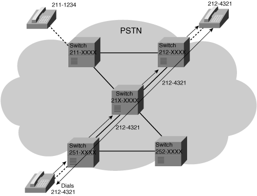
![]() Figure 8-12 illustrates how the NANP routes telephone calls. In this example, the lower telephone is dialing 212-4321, which is the telephone number of the top-right phone. A PSTN switch forwards the signal as soon as it receives enough digits to send the call to the next switch. The last switch in the path receives all the digits and rings the destination telephone (in this case, the telephone at the top right).
Figure 8-12 illustrates how the NANP routes telephone calls. In this example, the lower telephone is dialing 212-4321, which is the telephone number of the top-right phone. A PSTN switch forwards the signal as soon as it receives enough digits to send the call to the next switch. The last switch in the path receives all the digits and rings the destination telephone (in this case, the telephone at the top right).
| Note |
|
United Kingdom National Numbering Plan
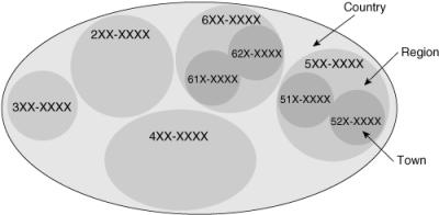
![]() The U.K. national numbering plan is another example of a national PSTN numbering plan conforming to the ITU-T recommendation E.164. Figure 8-13 shows a portion of the U.K. national numbering plan. It supports several geographic numbering options, depending on the population density of the city or area. It also reserves some number ranges for corporate uses.
The U.K. national numbering plan is another example of a national PSTN numbering plan conforming to the ITU-T recommendation E.164. Figure 8-13 shows a portion of the U.K. national numbering plan. It supports several geographic numbering options, depending on the population density of the city or area. It also reserves some number ranges for corporate uses.
|
| |
|---|---|
|
|
|
|
|
|
|
|
|
|
|
|
|
|
|
|
|
|
Figure 8-13: A Portion of the U.K. National Numbering Plan

2 comments
Voice Over Services
Nice Article.
Voice Over Services
Thanks for sharing this blog.
Post a Comment