
Configuring Inter-VLAN Routing
![]() This section focuses on the configuration of Inter-VLAN routing using various methods. The following are some of the configurations discussed in this section:
This section focuses on the configuration of Inter-VLAN routing using various methods. The following are some of the configurations discussed in this section:
-
 Inter-VLAN configuration with external router
 - Inter-VLAN configuration with SVI
- Routing configuration with routed ports
- Verifying and troubleshooting inter-VLAN routing
- Layer 3 EtherChannel configuration
- Routing protocol configuration
Inter-VLAN Configuration with External Router
![]() Before implementing inter-VLAN routing, a network engineer should plan the steps necessary to make it successful.
Before implementing inter-VLAN routing, a network engineer should plan the steps necessary to make it successful.
Implementation Planning
![]() Prior planning can help reduce any problems during the installation by logically organizing the steps necessary and providing checkpoints and verification, as necessary. Following are the key points to plan the implementation for the external router configuration method:
Prior planning can help reduce any problems during the installation by logically organizing the steps necessary and providing checkpoints and verification, as necessary. Following are the key points to plan the implementation for the external router configuration method:
- You need to know how many VLANs need routing and their VLAN_Ids. In addition, know what ports connect to the router.
- A router interface providing inter-VLAN routing on a trunk link must be configured with a subinterface for each VLAN for which it will perform routing. Each subinterface on the physical link must then be configured with the same trunk encapsulation protocol. That protocol, usually 802.1Q (many Cisco switches also support the ISL protocol, but it is considered legacy technology), must match the encapsulation type configured on the switch side of the link, so you need to know the type of encapsulation.
- Make sure to have the same native VLAN on both devices. Because traffic on the native VLAN is not tagged, all native VLAN frames will be received as untagged Ethernet frames. Beginning with Cisco IOS version 12.1(3)T, the creation of a subinterface for the native VLAN is allowed. If the native VLAN is configured as a subinterface, the command encapsulation dot1q <vlan> native is used. With older IOS versions, the physical interface is configured as the gateway for the native VLAN, with no encapsulation command—just an IP address. All other, non-native VLANs have an 802.1Q tag inserted into their frames. These non-native VLANs are configured as subinterfaces on the router, and the VLANs must be defined as using 802.1Q encapsulation, with the VLAN associated with them being identified. The subinterface command encapsulation dot1q vlan accomplishes this task.
| Note |
|
![]() Because a switch port defined as a trunk forwards all Ethernet VLANs by default, no configuration is required on the switch for the non-native VLANs. Additional configuration might exist if the trunk is configured to enable only some VLANs to use the trunk, but the figure assumes the default behavior.
Because a switch port defined as a trunk forwards all Ethernet VLANs by default, no configuration is required on the switch for the non-native VLANs. Additional configuration might exist if the trunk is configured to enable only some VLANs to use the trunk, but the figure assumes the default behavior.
![]() To configure inter-VLAN routing using router-on-a-stick, perform the following steps:
To configure inter-VLAN routing using router-on-a-stick, perform the following steps:
| Note |
|
![]() Example 4-1 shows an example of configuring inter-VLAN routing between VLAN 1 and VLAN 2 on an external router on the interface FastEthernet0/0 and a Catalyst switch running Cisco IOS on interface FastEthernet 4/2. Configuration of a router is followed by the switch configuration to configure an interface as a trunk port.
Example 4-1 shows an example of configuring inter-VLAN routing between VLAN 1 and VLAN 2 on an external router on the interface FastEthernet0/0 and a Catalyst switch running Cisco IOS on interface FastEthernet 4/2. Configuration of a router is followed by the switch configuration to configure an interface as a trunk port.
| Note |
|
Router(config-if)#no shutdown
Router(config)# interface FastEthernet 0/0.1
Router(config-subif) description VLAN 1
Router(config-subif)# encapsulation dot1Q 1 native
Router(config-subif)# ip address 10.1.1.1 255.255.255.0
Router(config-subif)# exit
Router(config)# interface FastEthernet 0/0.2
Router(config-subif)# description VLAN 2
Router(config-subif)# encapsulation dot1Q 2
Router(config-subif)# ip address 10.2.2.1 255.255.255.0
Router(config-subif)# exit
Router(config)# end
#####Cisco IOS switch Trunking Configuration Connected to Interface
FastEthernet0/0
switch(config)# interface FastEthernet 4/2
switch(config-if)# switchport trunk encapsulation dot1q
switch(config-if)# switchport mode trunk
switch(config-if)# end
Inter-VLAN Configuration with SVI
Implementation Plan
![]() As previously discussed, before implementing inter-VLAN routing on a multilayer switch, a network engineer should plan the steps necessary to make it successful. Prior planning can help prevent any problems during the installation by logically organizing the necessary steps and providing checkpoints and verification, as necessary:
As previously discussed, before implementing inter-VLAN routing on a multilayer switch, a network engineer should plan the steps necessary to make it successful. Prior planning can help prevent any problems during the installation by logically organizing the necessary steps and providing checkpoints and verification, as necessary:
- The first step is to identify the VLANs that require a Layer 3 gateway within the multilayer switch. It is possible that not all VLANs will require the capability to reach other VLANs within the enterprise. For example, a company might have a VLAN in use in an R&D laboratory. The network designer determines that this VLAN should not have connectivity with other VLANs in the enterprise or to the Internet. However, the R&D VLAN is not a local VLAN but spans the switch fabric due to the presence of an R&D server in the data center, so it cannot simply be pruned from the trunk between the multilayer switch and the R&D lab switch. Such a VLAN might be configured without a Layer 3 gateway as one way of ensuring the desired segregation.
- If a VLAN that is to be routed by an SVI interface does not already exist on the multilayer switch, it must be created. Then create the SVI interface for each VLAN that needs to be routed within the multilayer switch.
- Find out what protocols needs to be configured on the SVI; for example, IP and such. Assuming the enterprise uses only IP as a routed protocol, a network engineer would then configure each SVI interface with an appropriate IP address and mask. Following this, the SVI interface needs to be enabled using the no shutdown interface command.
- If SVIs are used to provide Layer 3 forwarding services to their assigned VLAN (as opposed to only giving those VLANs the capability to reach the switch), all routed protocols in use in the enterprise must have their routing function enabled within the multilayer switch. (Layer 3 routing is not enabled by default in a multilayer switch.)
- Depending on the size of the network and the design provided by the network architect, the multilayer switch might need to exchange dynamic routing protocol updates with one or more other routing devices in the network. A network engineer must determine whether this need exists, and if so, configure an appropriate dynamic routing protocol on the multilayer switch. The choice of protocol may be specified by the network designer, or the choice may be left to the network engineer.
- Finally, after carefully considering the network structure, a network engineer can decide to exclude certain switchports from contributing to the SVI line-state up-and-down calculation. Any such switchports would be configured with the autostate exclude feature. Autostate is discussed more in the “SVI Autostate” section.
| Note |
|
Switch Virtual Interface Configuration
![]() To configure an SVI for inter-VLAN routing on a Catalyst switch, such as the Catalyst 6000 Series, perform these steps:
To configure an SVI for inter-VLAN routing on a Catalyst switch, such as the Catalyst 6000 Series, perform these steps:
|
|
|
|
|
|
|
|
|
|
|
|
|
|
|
| Note |
|
![]() Figure 4-9 shows a multilayer switch providing inter-VLAN routing for VLAN 10 and VLAN 20.
Figure 4-9 shows a multilayer switch providing inter-VLAN routing for VLAN 10 and VLAN 20.


![]() Example 4-2 shows the configuration of IP routing on a Catalyst 3560 by creating VLAN interfaces and assigning IP addresses and subnet masks to the interfaces. In addition, RIP is enabled as the routing protocol.
Example 4-2 shows the configuration of IP routing on a Catalyst 3560 by creating VLAN interfaces and assigning IP addresses and subnet masks to the interfaces. In addition, RIP is enabled as the routing protocol.
Enter configuration commands, one per line. End with CNTL/Z.
Switch(config)# ip routing
Switch(config)# router rip
Switch(config-router)# network 10.0.0.0
Switch(config)# interface vlan 10
Switch(config-if)# ip address 10.10.1.1 255.0.0.0
Switch(config-if)# no shutdown
Switch(config-if)# interface vlan 20
Switch(config-if)# ip address 10.20.1.1 255.255.255.0
Switch(config-if)# no shutdown
SVI Autostate
![]() By default, when SVI is created and enabled, the line state of an SVI with multiple ports on a VLAN is in the up state when it meets these conditions:
By default, when SVI is created and enabled, the line state of an SVI with multiple ports on a VLAN is in the up state when it meets these conditions:
- The VLAN exists and is active in the VLAN database on the switch.
- The VLAN interface exists and is not administratively down.
- At least one Layer 2 (access or trunk) port exists on the switch, has a link in the up state on this VLAN, and is in the spanning-tree forwarding state on the VLAN.
![]() The SVI interface is up when one Layer 2 port in that VLAN is in spanning-tree forwarding mode. When a VLAN has multiple ports, the default action is to take the SVI down as soon as all the ports belonging in the VLAN go down. This feature helps minimize problems such as routing black holes, which happens when a routing protocol uses VLAN interfaces and misinterprets a VLAN interface as fully operational if there is no interface up in that VLAN.
The SVI interface is up when one Layer 2 port in that VLAN is in spanning-tree forwarding mode. When a VLAN has multiple ports, the default action is to take the SVI down as soon as all the ports belonging in the VLAN go down. This feature helps minimize problems such as routing black holes, which happens when a routing protocol uses VLAN interfaces and misinterprets a VLAN interface as fully operational if there is no interface up in that VLAN.
![]() In some cases, when a port connects to some monitoring equipment and intrusion prevention sensors, the port stays up because it is only connected to the monitoring equipment. and because of that the VLAN interface stays up. The monitoring ports are not used for activating any data transfers like host ports, and it stays up most of the time. The switchport autostate exclude commands help in that scenario so that the VLAN goes down when all other ports in the VLAN (those connected to active hosts) go down except the ones configured with autostate exclude. The SVI autostate exclude feature configures a port so that it is not included in the SVI line-state up-and-down calculation and the SVI interface goes down if all others ports in that VLAN goes down, even if the ports configured with this feature stayed up. A network engineer would therefore need to carefully consider the implications of activating this feature on a trunk link.
In some cases, when a port connects to some monitoring equipment and intrusion prevention sensors, the port stays up because it is only connected to the monitoring equipment. and because of that the VLAN interface stays up. The monitoring ports are not used for activating any data transfers like host ports, and it stays up most of the time. The switchport autostate exclude commands help in that scenario so that the VLAN goes down when all other ports in the VLAN (those connected to active hosts) go down except the ones configured with autostate exclude. The SVI autostate exclude feature configures a port so that it is not included in the SVI line-state up-and-down calculation and the SVI interface goes down if all others ports in that VLAN goes down, even if the ports configured with this feature stayed up. A network engineer would therefore need to carefully consider the implications of activating this feature on a trunk link.
![]() To configure a Layer 2 switchport for autostate exclude, follow these two steps:
To configure a Layer 2 switchport for autostate exclude, follow these two steps:
|
|
|
|
|
|
Configuring Routed Port on a Multilayer Switch
![]() To configure routed ports, make sure to configure the respective interface as a Layer 3 interface using the no switchport interface command, if the default configurations of the interfaces are Layer 2 interfaces as with the Catalyst 3560 family of switches. In addition, assign an IP address and other Layer 3 parameters as necessary. The rest of the steps are similar, as mentioned in the configuration of Inter-VLAN routing using SVI.
To configure routed ports, make sure to configure the respective interface as a Layer 3 interface using the no switchport interface command, if the default configurations of the interfaces are Layer 2 interfaces as with the Catalyst 3560 family of switches. In addition, assign an IP address and other Layer 3 parameters as necessary. The rest of the steps are similar, as mentioned in the configuration of Inter-VLAN routing using SVI.
| Note |
|
![]() To configure the routed ports, follow the following steps:
To configure the routed ports, follow the following steps:
|
|
|
|
|
|
|
|
|
|
|
|
|
|
|
|
|
|
![]() Example 4-3 illustrates the configuration of routed ports for a Catalyst 3560 switch running Cisco IOS. In this example, if the port is a Layer 2 port, the switch returns an error message upon attempted configuration.
Example 4-3 illustrates the configuration of routed ports for a Catalyst 3560 switch running Cisco IOS. In this example, if the port is a Layer 2 port, the switch returns an error message upon attempted configuration.
Core(Coreonfig-if)# no switchport
Core(config-if)# ip address 10.10.1.1 255.255.255.252
Core(config-if)# exit
Core(config)# interface GigabitEthernet 1/2
Core(config-if)# ip address 10.20.1.254 255.255.255.252
% IP addresses may not be configured on L2 links.
Core(config-if)# no switchport
Core(config-if)# ip address 10.20.1.254 255.255.255.252
Verifying Inter-VLAN Routing
![]() This subsection focuses on commands used to verify configuration of InterVLAN routing. The verification commands are similar across any inter-VLAN routing methods. The following commands are useful to inter-VLAN routing verifications:
This subsection focuses on commands used to verify configuration of InterVLAN routing. The verification commands are similar across any inter-VLAN routing methods. The following commands are useful to inter-VLAN routing verifications:
- show ip interface interface_type_port | svi_number
- show interface interface_type_port | svi_number
- show running interface type_port | svi_number
- ping
- show vlan
- show interface trunk
| Note |
|
![]() The show interfaces command can be used to display the interface IP address configuration and status of a port. The interface can be used for SVI interface status, EtherChannel interface status, or a port status and its configuration. Example 4-4 shows the output of the show interfaces vlan command.
The show interfaces command can be used to display the interface IP address configuration and status of a port. The interface can be used for SVI interface status, EtherChannel interface status, or a port status and its configuration. Example 4-4 shows the output of the show interfaces vlan command.
Vlan20 is up, line protocol is up
Hardware is Ethernet SVI, address is 00D.588F.B604 (bia 00D.588F.B604)
Internet address is 10.1.20.1/24
MTU 1500 bytes, BW 1000000 Kbit, DLY 10 usec,
reliability 255/255, txload 1/255, rxload 1/255
Encapsulation ARPA, loopback not set
ARP type: ARPA, ARP Timeout 04:00:00
Last input never, output never, output hang never
Last clearing of "show interface" counters never
Input queue: 0/75/0/0 (size/max/drops/flushes); Total output drops: 0
Queueing strategy: fifo
Output queue: 0/40 (size/max)
5 minute input rate 0 bits/sec, 0 packets/sec
5 minute output rate 0 bits/sec, 0 packets/sec
0 packets input, 0 bytes, 0 no buffer
Received 0 broadcasts, 0 runts, 0 giants, 0 throttles
0 input errors, 0 CRC, 0 frame, 0 overrun, 0 ignored
0 packets output, 0 bytes, 0 underruns
0 output errors, 0 interface resets
0 output buffer failures, 0 output buffers swapped out
![]() In Example 4-4, the SVI interface for VLAN 20 shows a status of up/up because at least one port is active in VLAN 20. Note that the hardware is reported as Ethernet SVI indicating the virtual nature of the interface. The remainder of the output is similar to what would be seen on any router interface.
In Example 4-4, the SVI interface for VLAN 20 shows a status of up/up because at least one port is active in VLAN 20. Note that the hardware is reported as Ethernet SVI indicating the virtual nature of the interface. The remainder of the output is similar to what would be seen on any router interface.
![]() The show running-config command can be used to display the interface configuration of a Layer 3 routed interface. In Example 4-5, the interface is configured as a Layer 3 routed interface, as evident by the disabling of Layer 2 functionality through use of the no switchport command. Recall that the 30-bit mask means two IP addresses exist in that subnet, which means the switch interfaces might be connecting to only a single external device on this subnet, such as a router or firewall.
The show running-config command can be used to display the interface configuration of a Layer 3 routed interface. In Example 4-5, the interface is configured as a Layer 3 routed interface, as evident by the disabling of Layer 2 functionality through use of the no switchport command. Recall that the 30-bit mask means two IP addresses exist in that subnet, which means the switch interfaces might be connecting to only a single external device on this subnet, such as a router or firewall.
Building configuration...
!
interface FastEthernet2/8
no switchport
ip address 172.16.22.2 255.255.255.252
![]() In addition to this, the network administrator can use the show ip interface command to check and verify the IP properties configured on the ports.
In addition to this, the network administrator can use the show ip interface command to check and verify the IP properties configured on the ports.
![]() As shown in Example 4-6, interface fasthethernet0/24 is a routed port with the IP address 10.1.10.1.
As shown in Example 4-6, interface fasthethernet0/24 is a routed port with the IP address 10.1.10.1.
FastEthernet0/24 is up, line protocol is up
Internet address is 10.1.10.1/24
Broadcast address is 255.255.255.255
Address determined by setup command
MTU is 1500 bytes
Helper address is not set
Directed broadcast forwarding is disabled
Multicast reserved groups joined: 224.0.0.10
Outgoing access list is not set
Inbound access list is not set
Proxy ARP is enabled
Local Proxy ARP is disabled
Security level is default
Split horizon is enabled
ICMP redirects are always sent
ICMP unreachables are always sent
ICMP mask replies are never sent
IP fast switching is enabled
IP CEF switching is enabled
![]() After the router is properly configured and is connected to the network, it can communicate with other nodes on the network. To test IP connectivity to hosts, use the ping command.
After the router is properly configured and is connected to the network, it can communicate with other nodes on the network. To test IP connectivity to hosts, use the ping command.
Troubleshooting Inter-VLAN Problems
![]() To troubleshoot inter-VLAN routing issues, the following are some checkpoint implementations:
To troubleshoot inter-VLAN routing issues, the following are some checkpoint implementations:
- Correct VLANs on switches and trunks.
- Correct routes.
- Correct primary and secondary root bridges.
- Correct IP address and subnet masks.
![]() Table 4-3 lists the common problems that can be seen during Inter-VLAN routing configuration.
Table 4-3 lists the common problems that can be seen during Inter-VLAN routing configuration.
|
|
|
|---|---|
|
|
|
|
|
|
|
|
|
|
|
|
| Note |
|
![]() To plan how to troubleshoot the inter-VLAN problems, you need to first understand the implementation and design layout of the topology before starting the troubleshooting. The following subsection discusses the example of a troubleshooting plan.
To plan how to troubleshoot the inter-VLAN problems, you need to first understand the implementation and design layout of the topology before starting the troubleshooting. The following subsection discusses the example of a troubleshooting plan.
Example of a Troubleshooting Plan
![]() A company XYZ adding a new floor to the current network and based on this the current requirements are to make sure the users on the new floor 5 can communicate with users on other floors. The current issue is that users on floor 5 cannot communicate with user on the other floor. Following is the example of the implementation plan to install a new VLAN for their use and make sure it is routing to other VLANs.
A company XYZ adding a new floor to the current network and based on this the current requirements are to make sure the users on the new floor 5 can communicate with users on other floors. The current issue is that users on floor 5 cannot communicate with user on the other floor. Following is the example of the implementation plan to install a new VLAN for their use and make sure it is routing to other VLANs.
![]() Your implementation plan lists the following steps:
Your implementation plan lists the following steps:
|
|
|
|
|
|
|
|
|
|
|
|
![]() The troubleshooting plan might look like this:
The troubleshooting plan might look like this:
- If a new VLAN has been created:
- Was the VLAN created on all the switches?
- If VTP is configured, make sure VLANs are defined on the VTP server and are getting propagated across all the domains.
- Verify with a show vlan command.
-
- Make sure ports are in the right VLAN and trunking is working as expected:
- Did all access ports get the command switchport access VLAN 510 added?
- Were there any other ports that should have been added? If so, make those changes.
- Were these ports previously used? If so, make sure there are no extra commands enabled on these ports that can cause conflicts. If not, is the port enabled?
- Are the access ports set to switchport access and not trunks? If not, issue the command switchport mode access.
- Are the trunk ports set to trunk mode and manually prune all the VLAN.
- Is manual pruning of VLANs a possibility? If so, make sure that the trunks necessary to carry this VLAN traffic have the VLAN in the allowed statements.
-
- If SVI interfaces are created
- Verify connectivity.
- Are all the links between the different switches on the path enabling this VLAN to be transported?
- Are all the links between switches in trunk mode?
- Is this VLANs allowed on all trunks?
- Is spanning-tree blocking one of those links?
- Are the ports enabled?
- Does the host have the right default gateway assigned.
- Also make sure the default route or some routing protocol is enabled if it needs to talk to other routers.
-
Configuration of Layer 3 EtherChannel
![]() To configure Layer 3 EtherChannel, follow these steps for configuring and verifying a Layer 3 EtherChannel interface:
To configure Layer 3 EtherChannel, follow these steps for configuring and verifying a Layer 3 EtherChannel interface:
|
|
|
|
|
|
|
|
|
|
|
|
|
|
|
|
|
|
| Note |
|
![]() Figure 4-10 shows a sample configuration for two switches using a Layer 3 EtherChannel bundle. The left switch has created a virtual interface with an IP address, and the physical interfaces are assigned to the matching channel-group number. The same is true with the right switch. Again, the virtual portchannel interfaces do not need to have the same number as any of the partner switches.
Figure 4-10 shows a sample configuration for two switches using a Layer 3 EtherChannel bundle. The left switch has created a virtual interface with an IP address, and the physical interfaces are assigned to the matching channel-group number. The same is true with the right switch. Again, the virtual portchannel interfaces do not need to have the same number as any of the partner switches.


![]() As illustrated in Figure 4-10, the following guidelines are followed to create the Layer 3 EtherChannel:
As illustrated in Figure 4-10, the following guidelines are followed to create the Layer 3 EtherChannel:
- Speed and duplex: Configure all interfaces in an EtherChannel to operate at the same speed and in the same duplex mode.
- Interface mode: As the port-channel interface is a routed port, the no switchport command was applied to it. The physical interfaces are by default switched, which is a mode incompatible with a router port. This is why the no switchport command was also applied to the physical ports, to make their mode compatible with the EtherChannel interface mode.
- Layer 3 configuration: Ensure the two switches connected using Layer 3 EtherChannel are configured with the IP addresses belonging to the same VLAN subnet with the correct subnet mask.
- Verifying the EtherChannel configuration: After EtherChannel is configured, use the following commands to verify and troubleshoot EtherChannel:
- show interface port-channel channel-group-number
- show etherChannel channel-group-number summary
- show spanning-tree vlan vlan-number detail
| Note |
|
Routing Protocol Configuration
![]() As soon as a multilayer switch is configured with Layer 3 IP addresses, it starts behaving like a router in the sense that it has connections to different subnets. Communication between these subnets can no longer be achieved using Layer 2 protocols. A major difference between a multilayer switch and a router is that a multilayer switch does not route until some Layer 3 or SVI interfaces are created.
As soon as a multilayer switch is configured with Layer 3 IP addresses, it starts behaving like a router in the sense that it has connections to different subnets. Communication between these subnets can no longer be achieved using Layer 2 protocols. A major difference between a multilayer switch and a router is that a multilayer switch does not route until some Layer 3 or SVI interfaces are created.
![]() When routing is enabled, the network administrator configures static routes and dynamic routing, just like on a router, as shown in Figure 4-11. In Figure 4-11, EIGRP is configured. Notice the passive interface commands. On a Layer 3 switch, a common recommendation is to enable dynamic routing only on those interfaces that need to exchange routing information with neighbors.
When routing is enabled, the network administrator configures static routes and dynamic routing, just like on a router, as shown in Figure 4-11. In Figure 4-11, EIGRP is configured. Notice the passive interface commands. On a Layer 3 switch, a common recommendation is to enable dynamic routing only on those interfaces that need to exchange routing information with neighbors.


![]() Wherever needed, summarization should also be configured to limit the size of the routing tables.
Wherever needed, summarization should also be configured to limit the size of the routing tables.
Verifying Routing Protocol
![]() To verify whether the routing protocol is working as expected, use the show ip route and show ip protocol commands.
To verify whether the routing protocol is working as expected, use the show ip route and show ip protocol commands.
![]() On a Layer 3 switch, just like on a router, use the show ip route command to display which Layer 3 routes are known to the local multilayer switch, as shown in Example 4-7. Each route type is identified by a code D, for example, which means routes are learned via EIGRP. In Example 4-7, the 10.1.10.0/24 subnet is directly connected (which can be identified with the letter C at the left of the route); the other routes are known via EIGRP (which can be identified with the letter D at the left of the route).
On a Layer 3 switch, just like on a router, use the show ip route command to display which Layer 3 routes are known to the local multilayer switch, as shown in Example 4-7. Each route type is identified by a code D, for example, which means routes are learned via EIGRP. In Example 4-7, the 10.1.10.0/24 subnet is directly connected (which can be identified with the letter C at the left of the route); the other routes are known via EIGRP (which can be identified with the letter D at the left of the route).
![]() Both 10.1.2.0/24 and 10.1.3.0/24 subnets are learned via 10.1.10.10. Their administrative distance is 90, and the cost to each of these networks is 28416. The link to 10.1.10.10 goes through the VLAN 10 interface. Notice that VLAN 10 here is the name of the SVI, the Layer 3 interface, through which the networks are reachable.
Both 10.1.2.0/24 and 10.1.3.0/24 subnets are learned via 10.1.10.10. Their administrative distance is 90, and the cost to each of these networks is 28416. The link to 10.1.10.10 goes through the VLAN 10 interface. Notice that VLAN 10 here is the name of the SVI, the Layer 3 interface, through which the networks are reachable.
Codes: C - connected, S - static, R - RIP, M - mobile, B - BGP
D - EIGRP, EX - EIGRP external, O - OSPF,
IA - OSPF inter area
N1 - OSPF NSSA external type 1,
N2 - OSPF NSSA external type 2
E1 - OSPF external type 1, E2 - OSPF external type 2
i - IS-IS, su - IS-IS summary, L1 - IS-IS level-1,
L2 - IS-IS level-2
ia - IS-IS inter area, * - candidate default,
U - per-user static route
o - ODR, P - periodic downloaded static route
Gateway of last resort is not set
10.0.0.0/8 is variably subnetted, 13 subnets, 2 masks
D 10.1.3.0/24 [90/28416] via 10.1.10.10, 08:09:49, Vlan10
D 10.1.2.0/24 [90/28416] via 10.1.10.10, 08:09:49, Vlan10
C 10.1.10.0/24 is directly connected, Vlan10
![]() The show ip protocol command shows information about the routing protocols that are enabled on the switch or router, as shown in Example 4-8.
The show ip protocol command shows information about the routing protocols that are enabled on the switch or router, as shown in Example 4-8.
Routing Protocol is "eigrp 1"
Outgoing update filter list for all interfaces is not set
Incoming update filter list for all interfaces is not set
Default networks flagged in outgoing updates
Default networks accepted from incoming updates
EIGRP metric weight K1=1, K2=0, K3=1, K4=0, K5=0
EIGRP maximum hopcount 100
EIGRP maximum metric variance 1
Redistributing: eigrp 1
Automatic network summarization is in effect
Maximum path: 4
Routing for Networks:
10.0.0.0
Passive Interface(s):
Vlan1
Vlan11
Routing Information Sources:
Gateway Distance Last Update
10.100.117.202 90 20:25:10
10.100.113.201 90 20:25:10
Distance: internal 90 external 170
Implementing Dynamic Host Configuration Protocol in a Multilayer Switched Environment
![]() As defined in RFC 2131, Dynamic Host Configuration Protocol (DHCP) provides configuration parameters to Internet hosts. DHCP consists of two components: a protocol for delivering host-specific configuration parameters from a DHCP server to a host, and a mechanism for allocating network addresses to hosts. DHCP is built on a client/server model in which designated DHCP server hosts allocate network addresses and deliver configuration parameters to dynamically configured hosts. By default, Cisco multilayer switches running Cisco IOS Software include DHCP server and relay agent software.
As defined in RFC 2131, Dynamic Host Configuration Protocol (DHCP) provides configuration parameters to Internet hosts. DHCP consists of two components: a protocol for delivering host-specific configuration parameters from a DHCP server to a host, and a mechanism for allocating network addresses to hosts. DHCP is built on a client/server model in which designated DHCP server hosts allocate network addresses and deliver configuration parameters to dynamically configured hosts. By default, Cisco multilayer switches running Cisco IOS Software include DHCP server and relay agent software.
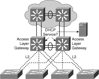
![]() Distribution multilayer switches often act as Layer 3 gateways for clients connecting to the access switches on various VLANs. Therefore, the DHCP service can be provided directly by the distribution switches, as shown in Figure 4-12. Alternatively, DHCP services can be concentrated in an external, dedicated DHCP server, as also reflected in Figure 4-12. In that case, distribution switches need to redirect the incoming clients DHCP requests to the external DHCP server.
Distribution multilayer switches often act as Layer 3 gateways for clients connecting to the access switches on various VLANs. Therefore, the DHCP service can be provided directly by the distribution switches, as shown in Figure 4-12. Alternatively, DHCP services can be concentrated in an external, dedicated DHCP server, as also reflected in Figure 4-12. In that case, distribution switches need to redirect the incoming clients DHCP requests to the external DHCP server.
![]() This section focuses on the following objectives:
This section focuses on the following objectives:
- DHCP operation
- DHCP configuration and verification
DHCP Operation
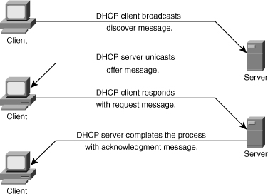
![]() Following are the steps that define the DHCP operation. Figure 4-13 illustrates the layout of the DHCP processs.
Following are the steps that define the DHCP operation. Figure 4-13 illustrates the layout of the DHCP processs.
|
|
|
|
|
|
|
|
|
|
|
|
Configuring DHCP and Verifying DHCP
![]() This subsection discusses the configuration and verification of DHCP. As previously discussed, the DHCP server can be configured on the router/multilayer switches or reside on the external server, and the multilayer switch or router can act as a DHCP relay agent.
This subsection discusses the configuration and verification of DHCP. As previously discussed, the DHCP server can be configured on the router/multilayer switches or reside on the external server, and the multilayer switch or router can act as a DHCP relay agent.
Configure DHCP on the Multilayer Switch
![]() To configure the DHCP service on a multilayer switch, follow these steps:
To configure the DHCP service on a multilayer switch, follow these steps:
|
|
|
|
|
|
|
|
|
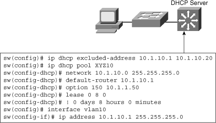
![]() A last important point to notice is that a multilayer switch can only offer IP addresses for a subnet in which it has an IP address. In other words, the switch in Figure 4-14 could not offer IP addresses in a 10.1.10.0/24 subnet if the switch itself did not have a Layer 3 IP address in this subnet. After this Layer 3 address is configured, all devices connecting to the switch through this interface can request an IP address. If the Layer 3 interface is a router port, all devices connecting to this routed port can request a DHCP IP address. If the Layer 3 interface in an SVI, all devices in the SVI VLAN in this scenario VLAN 10 can request a DHCP IP address. Figure 4-14 shows the configuration of DHCP on the switch for VLAN 10 with subnet 10.1.10.0. With the DHCP request, it mentions the default gateway and lease information.
A last important point to notice is that a multilayer switch can only offer IP addresses for a subnet in which it has an IP address. In other words, the switch in Figure 4-14 could not offer IP addresses in a 10.1.10.0/24 subnet if the switch itself did not have a Layer 3 IP address in this subnet. After this Layer 3 address is configured, all devices connecting to the switch through this interface can request an IP address. If the Layer 3 interface is a router port, all devices connecting to this routed port can request a DHCP IP address. If the Layer 3 interface in an SVI, all devices in the SVI VLAN in this scenario VLAN 10 can request a DHCP IP address. Figure 4-14 shows the configuration of DHCP on the switch for VLAN 10 with subnet 10.1.10.0. With the DHCP request, it mentions the default gateway and lease information.
Configure DHCP Relay
![]() DHCP is a client-server application, in which the DHCP client, usually a desktop computer, contacts a DHCP server for configuration parameters using a broadcast request. Today’s enterprise networks consist of multiple VLANs, where inter-VLAN routing routes between the subnetworks. Because Layer 3 devices do not pass broadcasts by default, each subnet requires a DHCP server unless the routers are configured to forward the DHCP broadcast using the DHCP relay agent feature using ip helper-address command. The ip helper-address command not only forwards DHCP UDP packets but also forwards TFTP, DNS, Time, NetBIOS, name server, and BOOTP packets by default.
DHCP is a client-server application, in which the DHCP client, usually a desktop computer, contacts a DHCP server for configuration parameters using a broadcast request. Today’s enterprise networks consist of multiple VLANs, where inter-VLAN routing routes between the subnetworks. Because Layer 3 devices do not pass broadcasts by default, each subnet requires a DHCP server unless the routers are configured to forward the DHCP broadcast using the DHCP relay agent feature using ip helper-address command. The ip helper-address command not only forwards DHCP UDP packets but also forwards TFTP, DNS, Time, NetBIOS, name server, and BOOTP packets by default.
![]() As illustrated in Figure 4-15, an ip helper-address command must be configured under the multilayer switch Layer 3 interface. This ip helper-address command points to the corporate DHCP server IP address. As shown in Figure 4-15, under VLAN 10, using ip helper-address command points to the DHCP server address 10.1.100.1.
As illustrated in Figure 4-15, an ip helper-address command must be configured under the multilayer switch Layer 3 interface. This ip helper-address command points to the corporate DHCP server IP address. As shown in Figure 4-15, under VLAN 10, using ip helper-address command points to the DHCP server address 10.1.100.1.


![]() When the switch receives a DHCP request broadcast message from a client, the switch forwards this request, as a unicast message, to the IP address specified under the ip helper command. With this feature, the switch relays the dialog between the DHCP client and the DHCP server. When the switch receive the packets, it makes sure it assign an IP address only from the range of the subnet in which the client resides.
When the switch receives a DHCP request broadcast message from a client, the switch forwards this request, as a unicast message, to the IP address specified under the ip helper command. With this feature, the switch relays the dialog between the DHCP client and the DHCP server. When the switch receive the packets, it makes sure it assign an IP address only from the range of the subnet in which the client resides.
Verifying DHCP Operation
![]() To verify the DHCP operation, use the following two commands:
To verify the DHCP operation, use the following two commands:
- show ip dhcp binding
- debug ip dhcp server packet
![]() Example 4-9 shows the output of the command show ip dhcp binding to find out the IP address assigned by the DHCP service on the switch and information regarding the IP addresses such as lease, MAC address, and so on.
Example 4-9 shows the output of the command show ip dhcp binding to find out the IP address assigned by the DHCP service on the switch and information regarding the IP addresses such as lease, MAC address, and so on.
Bindings from all pools not associated with VRF:
IP address Client-ID/ Lease expiration Type
Hardware address/
User name
10.1.10.21 0100.1bd5.132a.d2 Jun 25 2009 06:09 AM Automatic
10.1.10.22 0100.4096.a46a.90 Jun 25 2009 09:40 AM Automatic
10.1.10.23 0100.4096.aa98.95 Jun 25 2009 11:28 AM Automatic
![]() Example 4-10 shows the output of the debug command to verify the DHCP services on the switch. As illustrated, a client with mac-address 0100.1bd5.132a.d2 sends the request on VLAN 6. The DHCP server responds with the IP address 10.1.10.21, and then clients send the acceptance and DHCP services reply with the acknowledgment.
Example 4-10 shows the output of the debug command to verify the DHCP services on the switch. As illustrated, a client with mac-address 0100.1bd5.132a.d2 sends the request on VLAN 6. The DHCP server responds with the IP address 10.1.10.21, and then clients send the acceptance and DHCP services reply with the acknowledgment.
DHCPD: DHCPDISCOVER received from client 0100.1bd5.132a.d2 on interface Vlan6.
DHCPD: Sending DHCPOFFER to client 0100.1bd5.132a.d2 (10.1.10.21).
DHCPD: broadcasting BOOTREPLY to client 001b.d513.2ad2.
DHCPD: DHCPREQUEST received from client 0100.1bd5.132a.d2.
DHCPD: Sending DHCPACK to client 0100.1bd5.132a.d2 (10.1.10.21).
DHCPD: broadcasting BOOTREPLY to client 001b.d513.2ad2.
0 comments
Post a Comment