
Overview
![]() Network topologies generally associate VLANs with individual networks or subnetworks. However, network devices in different VLANs cannot communicate with each other without a Layer 3 switch or a router to forward traffic between the VLANs. The initial VLAN design recommends that each VLAN is associated with a different subnet as a best practice, therefore inter-VLAN routing is required to route traffic between VLANs. Cisco provides several solutions to enable inter-VLAN routing. Many Catalyst switches have integrated Layer 3 routing capabilities using hardware switching to achieve line-rate performance. In addition, several families of switches use Layer 3 modules to provide inter-VLAN routing.
Network topologies generally associate VLANs with individual networks or subnetworks. However, network devices in different VLANs cannot communicate with each other without a Layer 3 switch or a router to forward traffic between the VLANs. The initial VLAN design recommends that each VLAN is associated with a different subnet as a best practice, therefore inter-VLAN routing is required to route traffic between VLANs. Cisco provides several solutions to enable inter-VLAN routing. Many Catalyst switches have integrated Layer 3 routing capabilities using hardware switching to achieve line-rate performance. In addition, several families of switches use Layer 3 modules to provide inter-VLAN routing.
![]() This chapter discusses the advantages and disadvantages of different methods of inter-VLAN routing. In addition, it discusses how to plan, implement, and verify inter-VLAN routing using a variety of methods. This chapter also discusses how to configure and implement Dynamic Host Configuration Host (DHCP). Finally, it mentions how a multilayer switch forwards Layer 3 traffic using CEF. CEF is one of the Cisco methods of switches. This chapter goes into detail on how CEF builds and utilizes hardware tables to perform multilayer switching.
This chapter discusses the advantages and disadvantages of different methods of inter-VLAN routing. In addition, it discusses how to plan, implement, and verify inter-VLAN routing using a variety of methods. This chapter also discusses how to configure and implement Dynamic Host Configuration Host (DHCP). Finally, it mentions how a multilayer switch forwards Layer 3 traffic using CEF. CEF is one of the Cisco methods of switches. This chapter goes into detail on how CEF builds and utilizes hardware tables to perform multilayer switching.
![]() Upon completing this chapter, you will be able to implement inter-VLAN routing in a campus network. This ability includes being able to meet these objectives:
Upon completing this chapter, you will be able to implement inter-VLAN routing in a campus network. This ability includes being able to meet these objectives:
-
 Given an enterprise network, design, plan, implement, and verify inter-VLAN routing using an external router or a multilayer switch, using either switch virtual interfaces or routed interfaces.
 - Understand DHCP operation and its implementation and verification in given enterprise network.
- Implement and verify Cisco Express Forwarding (CEF) on a Cisco Catalyst multilayer switch.
Describing Inter-VLAN Routing
![]() Following the recommendation from Campus design, the distribution and Collapsed Core switches always have many VLANs terminating to these switches. Switches at the distribution layer, or in a collapsed core, will almost certainly have multiple VLANs connected to them. A switch with multiple VLANs requires a means of passing Layer 3 traffic to communicate between those VLANs.
Following the recommendation from Campus design, the distribution and Collapsed Core switches always have many VLANs terminating to these switches. Switches at the distribution layer, or in a collapsed core, will almost certainly have multiple VLANs connected to them. A switch with multiple VLANs requires a means of passing Layer 3 traffic to communicate between those VLANs.
![]() This section describes the process and the various methods of routing traffic from VLAN to VLAN. A router that is external to the Layer 2 switch hosting the VLANs can perform inter-VLAN routing. In addition, Cisco Catalyst multilayer switch can be used to perform both intra-VLAN frame forwarding and inter-VLAN routing.
This section describes the process and the various methods of routing traffic from VLAN to VLAN. A router that is external to the Layer 2 switch hosting the VLANs can perform inter-VLAN routing. In addition, Cisco Catalyst multilayer switch can be used to perform both intra-VLAN frame forwarding and inter-VLAN routing.
![]() This section focuses on how to perform inter-VLAN packet transfer using an external router and a multilayer switch. These sections focus on the following objectives:
This section focuses on how to perform inter-VLAN packet transfer using an external router and a multilayer switch. These sections focus on the following objectives:
- Introduction to inter-VLAN routing
- Inter-VLAN routing with an external router
- Inter-VLAN routing with switch virtual interfaces
- Routing with routed ports
Introduction to Inter-VLAN Routing
![]() Because VLANs isolate traffic to a defined broadcast domain and subnet, network devices in different VLANs cannot communicate with each other natively. As shown in Figure 4-1, the devices in different VLANs cannot communicate without any Layer 3 device. The devices in each VLAN can communicate to the network devices in another VLAN only through a Layer 3 routing device, referred to as an inter-VLAN router (see Figure 4-2). Cisco recommends the implementation of routing in the distribution or core switches of the multilayer switched network to terminate local VLANs. This helps to isolate network problems and to prevent them from affecting the campus backbone. In addition, packet manipulation and control of the traffic across VLANs is simplified by routing in the distribution layer instead of the core layer.
Because VLANs isolate traffic to a defined broadcast domain and subnet, network devices in different VLANs cannot communicate with each other natively. As shown in Figure 4-1, the devices in different VLANs cannot communicate without any Layer 3 device. The devices in each VLAN can communicate to the network devices in another VLAN only through a Layer 3 routing device, referred to as an inter-VLAN router (see Figure 4-2). Cisco recommends the implementation of routing in the distribution or core switches of the multilayer switched network to terminate local VLANs. This helps to isolate network problems and to prevent them from affecting the campus backbone. In addition, packet manipulation and control of the traffic across VLANs is simplified by routing in the distribution layer instead of the core layer.


![]() The following devices can provide inter-VLAN routing:
The following devices can provide inter-VLAN routing:
- Any Layer 3 multilayer Catalyst switch
- Any external router with an interface that supports trunking (router-on-a-stick)
- Any external router or group of routers with a separate interface in each VLAN
| Note |
|
![]() Router-on-a-stick is simple to implement because routers are usually available in every network, but most enterprise networks use multilayer switches to achieve high packet-processing rates using hardware switching. In addition, Layer 3 switches usually have packet-switching throughputs in the millions of packets per second (pps), whereas traditional general-purpose routers provide packet switching in the range of 100,000 pps to more than 1 million pps.
Router-on-a-stick is simple to implement because routers are usually available in every network, but most enterprise networks use multilayer switches to achieve high packet-processing rates using hardware switching. In addition, Layer 3 switches usually have packet-switching throughputs in the millions of packets per second (pps), whereas traditional general-purpose routers provide packet switching in the range of 100,000 pps to more than 1 million pps.
![]() All the Catalyst multilayer switches support three different types of Layer 3 interfaces:
All the Catalyst multilayer switches support three different types of Layer 3 interfaces:
- Routed port: A pure Layer 3 interface similar to a routed port on a Cisco IOS router.
- Switch virtual interface (SVI): A virtual VLAN interface for inter-VLAN routing. In other words, SVIs are the virtual routed VLAN interfaces.
- Bridge virtual interface (BVI): A Layer 3 virtual bridging interface.
![]() Because of high-performance switches such as the Catalyst 6500 and Catalyst 4500, almost every function, from spanning tree to routing, is done through hardware switching using features such as MLS and Cisco Express Forwarding (CEF)-based MLS, both of which are discussed in detail in later sections of this chapter.
Because of high-performance switches such as the Catalyst 6500 and Catalyst 4500, almost every function, from spanning tree to routing, is done through hardware switching using features such as MLS and Cisco Express Forwarding (CEF)-based MLS, both of which are discussed in detail in later sections of this chapter.
![]() All Layer 3 Cisco Catalyst switches support routing protocols, but several models of Catalyst switches require enhanced software for specific routing protocol features. Table 4-1 lists the Catalyst switches and their capabilities to support Layer 3.
All Layer 3 Cisco Catalyst switches support routing protocols, but several models of Catalyst switches require enhanced software for specific routing protocol features. Table 4-1 lists the Catalyst switches and their capabilities to support Layer 3.
|
|
|
|
|---|---|---|
|
|
|
|
|
|
|
|
|
|
|
|
|
|
|
|
![]() Catalyst switches use different default settings for interfaces. For example, all members of the Catalyst 3550 and 4500 families of switches use Layer 2 interfaces by default, whereas members of the Catalyst 6500 family of switches running Cisco IOS use Layer 3 interfaces by default. Recall that default interface configurations do not appear in the running or startup configuration. As a result, depending on which Catalyst family of switches is used, the switchport or no switchport command might be present in the running-config or startup-config files.
Catalyst switches use different default settings for interfaces. For example, all members of the Catalyst 3550 and 4500 families of switches use Layer 2 interfaces by default, whereas members of the Catalyst 6500 family of switches running Cisco IOS use Layer 3 interfaces by default. Recall that default interface configurations do not appear in the running or startup configuration. As a result, depending on which Catalyst family of switches is used, the switchport or no switchport command might be present in the running-config or startup-config files.
| Note |
|
Inter-VLAN Routing Using an External Router (Router-on-a-Stick)
![]() If a switch supports multiple VLANs but has no Layer 3 capability to route packets between those VLANs, the switch must be connected to a device external to the switch that possesses this capability. That device is normally a router, although it could be a multilayer switch (discussed in later subsections). This setup is not a high performance solution but it is quite simple. It just needs a single trunk link between the switch and the router. This single physical link should be Fast Ethernet or greater, although 802.1Q is supported on some new router 10-Mb Ethernet interfaces.
If a switch supports multiple VLANs but has no Layer 3 capability to route packets between those VLANs, the switch must be connected to a device external to the switch that possesses this capability. That device is normally a router, although it could be a multilayer switch (discussed in later subsections). This setup is not a high performance solution but it is quite simple. It just needs a single trunk link between the switch and the router. This single physical link should be Fast Ethernet or greater, although 802.1Q is supported on some new router 10-Mb Ethernet interfaces.
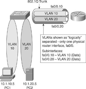
![]() Figure 4-3 shows a configuration where the router is connected to a core switch using a single 802.1Q trunk link. This configuration is commonly referred to as router-on-a-stick. The router can receive packets on one VLAN, for example on VLAN 10, and forward them to another VLAN, for example on VLAN 20. To support 802.1Q trunking, subdivide the physical router interface into multiple, logical, addressable interfaces, one per VLAN. The resulting logical interfaces are called subinterfaces.
Figure 4-3 shows a configuration where the router is connected to a core switch using a single 802.1Q trunk link. This configuration is commonly referred to as router-on-a-stick. The router can receive packets on one VLAN, for example on VLAN 10, and forward them to another VLAN, for example on VLAN 20. To support 802.1Q trunking, subdivide the physical router interface into multiple, logical, addressable interfaces, one per VLAN. The resulting logical interfaces are called subinterfaces.
![]() Assume that client PC-1 needs to send traffic to server PC-2, as shown in Figure 4-4. Because the hosts are on different VLANs, transferring this traffic requires a Layer 3 device. In this example, an external router connects to the switch via an 802.1Q trunk—a router-on-a-stick.
Assume that client PC-1 needs to send traffic to server PC-2, as shown in Figure 4-4. Because the hosts are on different VLANs, transferring this traffic requires a Layer 3 device. In this example, an external router connects to the switch via an 802.1Q trunk—a router-on-a-stick.
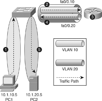
![]() Table 4-2 describes the actions necessary for traffic to be routed between VLANs using an external router, as illustrated in Figure 4-4.
Table 4-2 describes the actions necessary for traffic to be routed between VLANs using an external router, as illustrated in Figure 4-4.
External Router: Advantages and Disadvantages
![]() Every method of inter-VLAN routing has it advantages and disadvantages. The following are the advantage of the router-on-a-stick method:
Every method of inter-VLAN routing has it advantages and disadvantages. The following are the advantage of the router-on-a-stick method:
- It works with any switch that supports VLANs and trunking because Layer 3 services are not required on the switch. Many switches do not contain Layer 3 forwarding capability, especially switches used at the access layer of a hierarchical network, as listed in Table 4-1. If using Local VLANs, mostly none of the switches at the access layer have Layer 3 forwarding capability. Depending on the network design, it might be possible to have no Layer 3-capable switches at all.
- The implementation is simple. Only one switch port and one router interface require configuration. If the switch enables all VLANs to cross the trunk (the default), it literally takes only a few commands to configure the switch.
- The router provides communication between VLANs. If the network design includes only Layer 2 switches, this makes the design and troubleshooting traffic flow simply because only one place in the network exists where VLANs inter-connect.
![]() The following are some of the disadvantages of using the external router for inter-VLAN routing:
The following are some of the disadvantages of using the external router for inter-VLAN routing:
- A single traffic path may become congested. With a router-on-a-stick model, the trunk link is limited by the speed of the router interface shared across all trunked VLANs. Depending on the size of the network, the amount of inter-VLAN traffic, and the speed of the router interface, congestion could result with this design.
- Latency might be higher as frames leave and re-enter the switch chassis multiple times and the router makes software-based routing decisions. Latency increases any time traffic must flow between devices. Additionally, routers make routing decisions in software, which always incurs a greater latency penalty than switching with hardware.
Inter-VLAN Routing Using Switch Virtual Interfaces
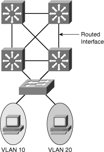
![]() In the early days of switched networks, switching was fast (often at hardware speed) and routing was slow (routing had to be processed in software). This prompted network designers to extend the switched part of the network as much as possible. Access, distribution, and core layers were often partly configured to communicate at Layer 2. This architecture is referred as switched, as shown in Figure 4-5. This topology created loop issues. To solve these issues, spanning-tree technologies were used to prevent loops while still enabling flexibility and redundancy in inter-switch connections.
In the early days of switched networks, switching was fast (often at hardware speed) and routing was slow (routing had to be processed in software). This prompted network designers to extend the switched part of the network as much as possible. Access, distribution, and core layers were often partly configured to communicate at Layer 2. This architecture is referred as switched, as shown in Figure 4-5. This topology created loop issues. To solve these issues, spanning-tree technologies were used to prevent loops while still enabling flexibility and redundancy in inter-switch connections.


![]() As network technologies evolved, routing became faster and cheaper. Today, routing can be performed at hardware speed. One consequence of this evolution is that routing can be brought down to the core and the distribution layers without impacting network performance. As many users are in separate VLANs, and as each VLAN is usually a separate subnet, it is logical to configure the distribution switches as Layer 3 gateways for the users of each access switch VLAN. This implies that each distribution switch must have IP addresses matching each access switch VLAN. This architecture is referred to as routed, as shown in Figure 4-5.
As network technologies evolved, routing became faster and cheaper. Today, routing can be performed at hardware speed. One consequence of this evolution is that routing can be brought down to the core and the distribution layers without impacting network performance. As many users are in separate VLANs, and as each VLAN is usually a separate subnet, it is logical to configure the distribution switches as Layer 3 gateways for the users of each access switch VLAN. This implies that each distribution switch must have IP addresses matching each access switch VLAN. This architecture is referred to as routed, as shown in Figure 4-5.
![]() As reflected in Figure 4-5, between the distribution and the core layer, implement Layer 3 ports instead of L2. Because dynamic routing protocols can dynamically adapt to any change in the network topology, this new topology also eliminates Layer 2 loops. Between access and distribution switches, where Layer 2 connections remain, FlexLink technology can be used to activate only one link at a time or Layer 2 EtherChannel can be used, thus removing the risk of loops and the need for spanning tree.
As reflected in Figure 4-5, between the distribution and the core layer, implement Layer 3 ports instead of L2. Because dynamic routing protocols can dynamically adapt to any change in the network topology, this new topology also eliminates Layer 2 loops. Between access and distribution switches, where Layer 2 connections remain, FlexLink technology can be used to activate only one link at a time or Layer 2 EtherChannel can be used, thus removing the risk of loops and the need for spanning tree.
![]() An SVI is a virtual interface configured within a multilayer switch compared to external router configuration where the trunk is needed, as shown in Figure 4-6. An SVI can be created for any VLAN that exists on the switch, as illustrated in Figure 4-6. Only one VLAN associates with one SVI. An SVI is “virtual” in that there is no physical port dedicated to the interface, yet it can perform the same functions for the VLAN as a router interface would and can be configured in much the same way as a router interface (IP address, inbound/outbound ACLs, and so on). The SVI for the VLAN provides Layer 3 processing for packets to or from all switch ports associated with that VLAN.
An SVI is a virtual interface configured within a multilayer switch compared to external router configuration where the trunk is needed, as shown in Figure 4-6. An SVI can be created for any VLAN that exists on the switch, as illustrated in Figure 4-6. Only one VLAN associates with one SVI. An SVI is “virtual” in that there is no physical port dedicated to the interface, yet it can perform the same functions for the VLAN as a router interface would and can be configured in much the same way as a router interface (IP address, inbound/outbound ACLs, and so on). The SVI for the VLAN provides Layer 3 processing for packets to or from all switch ports associated with that VLAN.


![]() By default, an SVI is created for the default VLAN (VLAN1) to permit remote switch administration. Additional SVIs must be explicitly created. SVIs are created the first time the VLAN interface configuration mode is entered for a particular VLAN SVI (for instance, when the command interface vlan ## is entered). The VLAN number used corresponds to the VLAN tag associated with data frames on an 802.1Q encapsulated trunk or to the VLAN ID (VID) configured for an access port. For instance, if creating an SVI as a gateway for VLAN 10, name the SVI interface VLAN 10. Configure and assign an IP address to each VLAN SVI that is to route traffic off of and onto a VLAN.
By default, an SVI is created for the default VLAN (VLAN1) to permit remote switch administration. Additional SVIs must be explicitly created. SVIs are created the first time the VLAN interface configuration mode is entered for a particular VLAN SVI (for instance, when the command interface vlan ## is entered). The VLAN number used corresponds to the VLAN tag associated with data frames on an 802.1Q encapsulated trunk or to the VLAN ID (VID) configured for an access port. For instance, if creating an SVI as a gateway for VLAN 10, name the SVI interface VLAN 10. Configure and assign an IP address to each VLAN SVI that is to route traffic off of and onto a VLAN.
![]() Whenever the SVI is created, make sure that particular VLAN is present in the VLAN database manually or learned via VTP. As shown in Figure 4-6, the switch should have VLAN 10 and VLAN 20 present in the VLAN database; otherwise, the SVI interface will stay down.
Whenever the SVI is created, make sure that particular VLAN is present in the VLAN database manually or learned via VTP. As shown in Figure 4-6, the switch should have VLAN 10 and VLAN 20 present in the VLAN database; otherwise, the SVI interface will stay down.
![]() The following are some of the reasons to configure SVI:
The following are some of the reasons to configure SVI:
- To provide a gateway for a VLAN so that traffic can be routed into or out of that VLAN
- To provide fallback bridging if it is required for nonroutable protocols
Note Using fallback bridging, non-IP packets can be forwarded across the routed interfaces. This book focuses only on inter-VLAN routing, so only IP connectivity is discussed. - To provide Layer 3 IP connectivity to the switch
- To support routing protocol and bridging configurations
SVI: Advantages and Disadvantages
![]() The following are some of the advantage of SVI:
The following are some of the advantage of SVI:
- It is much faster than router-on-a-stick because everything is hardware switched and routed.
- No need for external links from the switch to the router for routing.
- Not limited to one link., Layer 2 EtherChannels can be used between the switches to get more bandwidth.
- Latency is much lower because it doesn’t need to leave the switch.
![]() The following are some of the disadvantages:
The following are some of the disadvantages:
- It needs a Layer 3 switch to perform Inter-VLAN routing, which is more expensive.
Routing with Routed Ports
![]() A routed port is a physical port that acts similarly to a port on a traditional router with Layer 3 addresses configured. Unlike an access port, a routed port is not associated with a particular VLAN. A routed port behaves like a regular router interface. Also, because Layer 2 functionality has been removed, Layer 2 protocols, such as STP and VTP, do not function on a routed interface. However, protocols such as LACP, which can be used to build either Layer 2 or Layer 3 EtherChannel bundles, would still function at Layer 3.
A routed port is a physical port that acts similarly to a port on a traditional router with Layer 3 addresses configured. Unlike an access port, a routed port is not associated with a particular VLAN. A routed port behaves like a regular router interface. Also, because Layer 2 functionality has been removed, Layer 2 protocols, such as STP and VTP, do not function on a routed interface. However, protocols such as LACP, which can be used to build either Layer 2 or Layer 3 EtherChannel bundles, would still function at Layer 3.
| Note |
|
![]() Routed ports are used for point-to-point links; connecting WAN routers and security devices are examples of the use of routed ports. In the campus switched network, routed ports are mostly configured between the switches in the campus backbone and between switches in the campus backbone and building distribution switches if Layer 3 routing is applied in the distribution layer. Figure 4-7 illustrates an example of routed ports for point-to-point links in a campus switched network.
Routed ports are used for point-to-point links; connecting WAN routers and security devices are examples of the use of routed ports. In the campus switched network, routed ports are mostly configured between the switches in the campus backbone and between switches in the campus backbone and building distribution switches if Layer 3 routing is applied in the distribution layer. Figure 4-7 illustrates an example of routed ports for point-to-point links in a campus switched network.
![]() To configure routed ports, make sure to configure the respective interface as a Layer 3 interface using the no switchport interface command, if the default configurations of the interfaces are Layer 2 interfaces as with the Catalyst 3560 family of switches. In addition, assign an IP address and other Layer 3 parameters as necessary. After assigning the IP address, make certain that IP routing is globally enabled and that applicable routing protocols are configured.
To configure routed ports, make sure to configure the respective interface as a Layer 3 interface using the no switchport interface command, if the default configurations of the interfaces are Layer 2 interfaces as with the Catalyst 3560 family of switches. In addition, assign an IP address and other Layer 3 parameters as necessary. After assigning the IP address, make certain that IP routing is globally enabled and that applicable routing protocols are configured.
![]() The number of routed ports and SVIs that can be configured on a switch is not limited by software. However, the interrelationship between these interfaces and other features configured on the switch may overload the CPU due to hardware limitations, so a network engineer should fully consider these limits before configuring these features on numerous interfaces.
The number of routed ports and SVIs that can be configured on a switch is not limited by software. However, the interrelationship between these interfaces and other features configured on the switch may overload the CPU due to hardware limitations, so a network engineer should fully consider these limits before configuring these features on numerous interfaces.
L2 EtherChannel Versus L3 EtherChannel
![]() The EtherChannel technology is available to bundle ports of the same type. On a Layer 2 switch, EtherChannel can aggregate access ports such as servers that support EtherChannel or trunk links to connect switches. As each EtherChannel link is seen as one logical connection, ports that are member of an EtherChannel can load balance traffic on all the links that are up.
The EtherChannel technology is available to bundle ports of the same type. On a Layer 2 switch, EtherChannel can aggregate access ports such as servers that support EtherChannel or trunk links to connect switches. As each EtherChannel link is seen as one logical connection, ports that are member of an EtherChannel can load balance traffic on all the links that are up.
![]() On Layer 3 switches, switched ports can be converted to routed ports. These ports do not perform switching at Layer 2 anymore, but become Layer 3 ports similar to those found on router platforms. Routed Layer 3 ports can also form EtherChannel just like Layer 2.
On Layer 3 switches, switched ports can be converted to routed ports. These ports do not perform switching at Layer 2 anymore, but become Layer 3 ports similar to those found on router platforms. Routed Layer 3 ports can also form EtherChannel just like Layer 2.
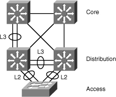
![]() On a multilayer switch, it is easy to configure Layer 2 EtherChannels or Layer 3 EtherChannels, depending on what type of devices connect and depending on their position in the network. The configuration requires that ports on both sides are configured the same way: switch ports (access or trunk) or routed ports. As shown in Figure 4-8, the bottom switch is Layer 2-only because it is an access switch, so Layer 2 EtherChannel is configured. At the distribution or the core layer, where Layer 3 links are recommended, Layer 3 EtherChannels are configured.
On a multilayer switch, it is easy to configure Layer 2 EtherChannels or Layer 3 EtherChannels, depending on what type of devices connect and depending on their position in the network. The configuration requires that ports on both sides are configured the same way: switch ports (access or trunk) or routed ports. As shown in Figure 4-8, the bottom switch is Layer 2-only because it is an access switch, so Layer 2 EtherChannel is configured. At the distribution or the core layer, where Layer 3 links are recommended, Layer 3 EtherChannels are configured.
2 comments
good job and hope all of people learn how it's work
for more info check my account
https://staff.najah.edu/en/profiles/administrative-staff/8713/
https://staff.najah.edu/en/profiles/administrative-staff/8713/
Post a Comment