
Deploying CEF-Based Multilayer Switching
Layer 3 switching provides a wire-speed mechanism by which to route packets between VLANs using tables that store Layer 2 and Layer 3 forwarding information in the hardware.
CEF-based MLS is an efficient forwarding model of Layer 3 switching implemented on the latest generation of Cisco multilayer switches. CEF-based MLS is topology-based, where the control plane and data plane are separate. The control plane downloads the routing table information to the data plane for hardware switching. CEF uses a specific process to build forwarding tables in the hardware and then uses that table’s information to forward packets at line speed. This section explains the mechanisms involved in Layer 2 and Layer 3 switching.
This section focuses on the following objectives:
-
Understand multilayer switching concepts and processing.
-
Describe the different switching methods that are available on a Cisco switch.
-
In a given enterprise environment describe, configure, and verify CEF on a Cisco switch.
Multilayer Switching Concepts
Traditionally, a switch makes forwarding decisions by looking at the Layer 2 header, whereas a router makes forwarding decisions by looking at the Layer 3 header.
A multilayer switch combines the functionality of a switch and a router into one device, thereby enabling the device to switch traffic when the source and destination are in the same VLAN and to route traffic when the source and destination are in different VLANs (that is, different subnets). A switch offloads a significant portion of the normal software-based routing process (packet rewrite) to hardware, so its Layer 3 forwarding process has also been termed switching, hence the term multilayer switching.
Layer 2 forwarding in hardware is based on the destination MAC address. The Layer 2 switch learns MAC address locations based on the source MAC address contained in incoming frames. The MAC address table lists MAC address and VLAN pairs with associated interfaces.
Layer 3 forwarding is based on the destination IP address. Layer 3 forwarding occurs when a packet is routed from a source in one subnet to a destination in another subnet. When a multilayer switch sees its own MAC address in the Layer 2 header, it recognizes that the packet is either destined for itself or has been sent to the switch so that it can act as a gateway toward the destination. If the packet is not destined for the multilayer switch, the destination IP address is compared against the Layer 3 forwarding table for the longest match. In addition, any router ACL checks are performed.
Traditionally, switches were handling Layer 2 frames at hardware speed, whereas routers were handling Layer 3 packets at software speed. Today, technology enables multilayer switches to route packets at hardware speed.
![]() This subsection discusses the following topics:
This subsection discusses the following topics:
Explaining Layer 3 Switch Processing
![]() Recall that a multilayer switch combines the functionality of a switch and a router into one device. Because a switch offloads a significant portion of the normal software-based routing process (packet rewrite) to the hardware, a multilayer switch processes more packets, faster than a traditional router by using specialized ASIC hardware instead of microprocessor-based engines.
Recall that a multilayer switch combines the functionality of a switch and a router into one device. Because a switch offloads a significant portion of the normal software-based routing process (packet rewrite) to the hardware, a multilayer switch processes more packets, faster than a traditional router by using specialized ASIC hardware instead of microprocessor-based engines.
![]() Because Layer 3 switches provide both wire-speed Ethernet routing and switching services, they are optimized for the campus LAN or intranet and are generally preferred over traditional routers for routing within such an environment.
Because Layer 3 switches provide both wire-speed Ethernet routing and switching services, they are optimized for the campus LAN or intranet and are generally preferred over traditional routers for routing within such an environment.
![]() A Layer 3 switch performs three major functions:
A Layer 3 switch performs three major functions:
-
 Packet switching
 - Route processing
- Intelligent network services
![]() The latter subsections discuss how the packets traverse through the multilayer switch.
The latter subsections discuss how the packets traverse through the multilayer switch.
Frame Rewrite
![]() When packets transit through a router or multilayer switch, the following verifications must occur, as shown in Figure 4-16:
When packets transit through a router or multilayer switch, the following verifications must occur, as shown in Figure 4-16:
- The incoming frame checksum is verified to ensure that no frame corruption or alteration occurs during transit.
- The incoming IP header checksum is verified to ensure that no packet corruption or alteration occurs during transit.


![]() IP unicast packets are rewritten on the output interface, as illustrated in Figure 4-17 and described as follows:
IP unicast packets are rewritten on the output interface, as illustrated in Figure 4-17 and described as follows:
- The destination MAC address changes from the router MAC address to the next-hop MAC address.
- The source MAC address changes from the sender MAC address to the outgoing router MAC address.
- The destination MAC address changes from the router MAC address to the next-hop MAC address.
- The TTL is decremented by one, and as a result, the IP header checksum is recalculated.
- The frame checksum must be recalculated.


![]() The switch obtains the information needed for the frame rewriting process from internal tables such as CAM and TCAM tables. Some of these tables are cached in ASICs or RAM. These tables are covered in the following subsections.
The switch obtains the information needed for the frame rewriting process from internal tables such as CAM and TCAM tables. Some of these tables are cached in ASICs or RAM. These tables are covered in the following subsections.
CAM and TCAM Tables
![]() This subsection describes the multilayer switching table architectures and how the CAM and TCAM tables are used.
This subsection describes the multilayer switching table architectures and how the CAM and TCAM tables are used.
![]() Multilayer switches build routing, bridging, QoS, and ACL tables for centralized or distributed switching in hardware using high-speed memory tables. Switches perform lookups in these tables for result information, such as to determine whether a packet with a specific destination IP address is supposed to be dropped according to an ACL. These tables support high-performance lookups and search algorithms such that multilayer switches maintain line-rate performance.
Multilayer switches build routing, bridging, QoS, and ACL tables for centralized or distributed switching in hardware using high-speed memory tables. Switches perform lookups in these tables for result information, such as to determine whether a packet with a specific destination IP address is supposed to be dropped according to an ACL. These tables support high-performance lookups and search algorithms such that multilayer switches maintain line-rate performance.
![]() Multilayer switches deploy these memory tables using specialized memory architectures, referred to as content addressable memory (CAM), and ternary content addressable memory (TCAM). CAM tables provide only two results: 0 (true) or 1 (false). CAM is most useful for building tables that search on exact matches such as MAC address tables. TCAM provides three results: 0, 1, and “don’t care.” TCAM is most useful for building tables for searching on the longest matches, such as IP routing tables organized by IP prefixes.
Multilayer switches deploy these memory tables using specialized memory architectures, referred to as content addressable memory (CAM), and ternary content addressable memory (TCAM). CAM tables provide only two results: 0 (true) or 1 (false). CAM is most useful for building tables that search on exact matches such as MAC address tables. TCAM provides three results: 0, 1, and “don’t care.” TCAM is most useful for building tables for searching on the longest matches, such as IP routing tables organized by IP prefixes.
![]() In addition, Catalyst switch architecture supports the capability to perform multiple lookups into multiple distinct CAM and TCAM regions in parallel. As a result of this capability to perform multiple lookups simultaneously, Catalyst switches do not suffer any performance degradation by enabling additional hardware-switching features such as QoS and IP ACL processing.
In addition, Catalyst switch architecture supports the capability to perform multiple lookups into multiple distinct CAM and TCAM regions in parallel. As a result of this capability to perform multiple lookups simultaneously, Catalyst switches do not suffer any performance degradation by enabling additional hardware-switching features such as QoS and IP ACL processing.
![]() The following summarizes the tables:
The following summarizes the tables:
- CAM table: The primary table used to make Layer 2 forwarding decisions. The table is built by recording the source MAC address and inbound port of all incoming frames. When a frame arrives at the switch with a destination MAC address of an entry in the CAM table, the frame is forwarded out through only the port that is associated with that specific MAC address.
- TCAM table: Stores ACL, QoS, and other information generally associated with Layer 3 and up layer processing.
![]() Table lookups are performed with efficient search algorithms. A key is created to compare the frame to the table content. For example, the destination MAC address and VLAN ID (VID) of a frame would constitute the key for Layer 2 table lookup. This key is input into a hashing algorithm, which produces, as the output, a pointer into the table. The system uses the pointer to access a specific entry in the table, thus eliminating the need to search the entire table.
Table lookups are performed with efficient search algorithms. A key is created to compare the frame to the table content. For example, the destination MAC address and VLAN ID (VID) of a frame would constitute the key for Layer 2 table lookup. This key is input into a hashing algorithm, which produces, as the output, a pointer into the table. The system uses the pointer to access a specific entry in the table, thus eliminating the need to search the entire table.
![]() In specific high-end switch platforms, the TCAM is a portion of memory designed for rapid, hardware-based table lookups of Layer 3 and Layer 4 information. In the TCAM, a single lookup provides all Layer 2 and Layer 3 forwarding information for frames, including CAM and ACL information.
In specific high-end switch platforms, the TCAM is a portion of memory designed for rapid, hardware-based table lookups of Layer 3 and Layer 4 information. In the TCAM, a single lookup provides all Layer 2 and Layer 3 forwarding information for frames, including CAM and ACL information.
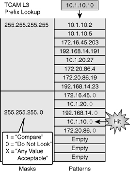
![]() TCAM matching is based on three values: 0, 1, or x (where x is either number), hence the term ternary. The memory structure is broken into a series of patterns and associated masks.
TCAM matching is based on three values: 0, 1, or x (where x is either number), hence the term ternary. The memory structure is broken into a series of patterns and associated masks.
![]() In a Layer 2 table, all bits of all information are significant for frame forwarding (for example, VLANs destination MAC addresses and destination protocol types). However, in more complicated tables associated with upper-layer forwarding criteria, a full analysis might not be required; some bits of information might be too inconsequential to analyze. For example, an ACL might require a match on the first 24 bits of an IP address but not concerned with the last 8 bits. This capability to “care” about only certain bits is a key factor to the lookup process for the TCAM table.
In a Layer 2 table, all bits of all information are significant for frame forwarding (for example, VLANs destination MAC addresses and destination protocol types). However, in more complicated tables associated with upper-layer forwarding criteria, a full analysis might not be required; some bits of information might be too inconsequential to analyze. For example, an ACL might require a match on the first 24 bits of an IP address but not concerned with the last 8 bits. This capability to “care” about only certain bits is a key factor to the lookup process for the TCAM table.
![]() Figure 4-18 displays an example of the TCAM table that would be used by a CEF prefix lookup to make a routing decision. Because the entry searched for, 10.1.10.10, does not appear as a pattern in the TCAM table when all bits are compared, the search continues with the patterns and fall back where only the first 24 bits are compared that happen to be the next match in this case, resulting in a hit.
Figure 4-18 displays an example of the TCAM table that would be used by a CEF prefix lookup to make a routing decision. Because the entry searched for, 10.1.10.10, does not appear as a pattern in the TCAM table when all bits are compared, the search continues with the patterns and fall back where only the first 24 bits are compared that happen to be the next match in this case, resulting in a hit.
![]() Although the figure uses an example of TCAM for routing lookups, the TCAM is also used to match patterns for QoS and ACLs (including VACLs), where multiple factors might be part of the input key, for example destination IP address and port number for an ACL entry.
Although the figure uses an example of TCAM for routing lookups, the TCAM is also used to match patterns for QoS and ACLs (including VACLs), where multiple factors might be part of the input key, for example destination IP address and port number for an ACL entry.
![]() Moreover, TCAM is divided into multiple protocol regions such as one region for ACL, one region for multicast, and one for IP-PREFIX, as shown in Table 4-4. TCAM also defines three different match options that correlate to specific match regions. These match regions are as follows:
Moreover, TCAM is divided into multiple protocol regions such as one region for ACL, one region for multicast, and one for IP-PREFIX, as shown in Table 4-4. TCAM also defines three different match options that correlate to specific match regions. These match regions are as follows:
- Exact-match region: Consists of Layer 3 entries for regions such as IP adjacencies. IP adjacencies are the next-hop information (MAC address) for an IP address. Other examples of exact-match regions are Layer 2 switching tables and UDP flooding tables.
- Longest-match region: Consists of multiple “buckets” or groups of Layer 3 address entries organized in decreasing order by mask length. All entries within a bucket share the same mask value and key size. The buckets change their size dynamically by borrowing address entries from neighboring buckets. Although the size of the whole protocol region is fixed, as mentioned in Table 4-4, several platforms support configuration of the region size. For most platforms, the reconfigured size of the protocol region is effective only after the next system reboot.
- First-match region: Consists of regions that stop lookups after the first match of the entry. An example of when a first-match region is used is for ACL entries.
|
|
|
|
|
|
|---|---|---|---|---|
|
|
|
|
|
|
|
|
|
|
|
|
|
|
|
|
|
|
|
|
|
|
|
|
|
|
|
|
|
|
|
|
|
|
|
|
![]() Table 4-4 illustrates the common protocol regions, lookup type, and key size found on Catalyst switches. The size of the regions and the ability to configure the region varies on each Catalyst switch family.
Table 4-4 illustrates the common protocol regions, lookup type, and key size found on Catalyst switches. The size of the regions and the ability to configure the region varies on each Catalyst switch family.
Distributed Hardware Forwarding
![]() In this subsection, the focus is on the concept of control and data planes.
In this subsection, the focus is on the concept of control and data planes.
![]() Layer 3 switching software employs a distributed architecture in which the control path and data path are relatively independent. The control path code, such as routing protocols, runs on the route processor, whereas the Ethernet interface module and the switching fabric forward most of the data packets.
Layer 3 switching software employs a distributed architecture in which the control path and data path are relatively independent. The control path code, such as routing protocols, runs on the route processor, whereas the Ethernet interface module and the switching fabric forward most of the data packets.
![]() Figure 4-19 shows a distributed hardware forwarding overview.
Figure 4-19 shows a distributed hardware forwarding overview.


![]() Each interface module includes a microcoded processor that handles all packet forwarding. Following are the main functions of the control layer between the routing protocol and the firmware datapath microcode:
Each interface module includes a microcoded processor that handles all packet forwarding. Following are the main functions of the control layer between the routing protocol and the firmware datapath microcode:
- Managing the internal data and control circuits for the packet-forwarding and control functions
- Extracting the other routing and packet-forwarding-related control information from the Layer 2 and Layer 3 bridging and routing protocols and the configuration data, and then conveying the information to the interface module for control of the data path
- Collecting the data path information, such as traffic statistics, from the interface module to the route processor
- Handling certain data packets sent from the Ethernet interface modules to the route processor
Cisco Switching Methods
![]() A Cisco router can use one of following three methods to forward packets:
A Cisco router can use one of following three methods to forward packets:
- Process Switching: In process switching, the router strips off the Layer 2 header for each incoming frame, looks up the Layer 3 destination network address in the routing table for each packet, and then sends the frame with rewritten Layer 2 header, including computed cyclical redundancy check (CRC), to the outgoing interface. All these operations are done by software running on the CPU for each individual frame. Process switching is the most CPU-intensive method available in Cisco routers. It can greatly degrade performance and is generally used only as a last resort or during troubleshooting.
- Fast Switching: After the lookup of the first packet destined for a particular IP network, the router initializes the fast-switching cache used by the Fast switching mode. When subsequent frames arrive, the destination is found in this fast-switching cache. The frame is rewritten with corresponding link addresses and is sent over the outgoing interface.
- Cisco Express Forwarding (CEF): The default-switching mode. CEF is less CPU-intensive than fast switching or process switching. A router with CEF enabled uses information from tables built by the CPU, such as the routing table and ARP table, to build hardware-based tables known as the Forwarding Information Base (FIB) and adjacency tables. These tables are then used to make hardware-based forwarding decisions for all frames in a data flow, even the first. Although CEF is the fastest switching mode, there are limitations, such as other features that are not compatible with CEF or rare instances in which CEF functions can actually degrade performance, such as CEF polarization in a topology using load-balanced Layer 3 paths.
![]() This section discusses the multilayer switching forwarding methods.
This section discusses the multilayer switching forwarding methods.
![]() A Layer 3 switch makes forwarding decisions using one of following two methods, which are platform-dependent:
A Layer 3 switch makes forwarding decisions using one of following two methods, which are platform-dependent:
- Route caching: Also known as flow-based or demand-based switching, a Layer 3 route cache is built within hardware functions as the switch sees traffic flow into the switch. This is functionally equivalent to Fast Switching in Router IOS.
- Topology-based switching: Information from the routing table is used to populate the route cache, regardless of traffic flow. The populated route cache is called the FIB. CEF is the facility that builds the FIB. CEF is discussed in more detailed in later sections. This is functionally equivalent to CEF in Router IOS.
Route Caching
![]() For route caching to function, the destination MAC address of an incoming frame must be that of a switch interface with Layer 3 capability, either an SVI or routed interface. The first packet in a stream is switched in software by the route processor because no cache entry exists yet for the new flow. The forwarding decision that is made by the route processor is then programmed into a cache table (the hardware forwarding table), and all subsequent packets in the flow are switched in the hardware. Entries are only created in the hardware-forwarding table as the switch sees new traffic flows and will time out after they have been unused for a period of time. As shown in Figure 4-20, when the host sends its first packet the traffic goes through the router processor and then the route processor fills up the cache.
For route caching to function, the destination MAC address of an incoming frame must be that of a switch interface with Layer 3 capability, either an SVI or routed interface. The first packet in a stream is switched in software by the route processor because no cache entry exists yet for the new flow. The forwarding decision that is made by the route processor is then programmed into a cache table (the hardware forwarding table), and all subsequent packets in the flow are switched in the hardware. Entries are only created in the hardware-forwarding table as the switch sees new traffic flows and will time out after they have been unused for a period of time. As shown in Figure 4-20, when the host sends its first packet the traffic goes through the router processor and then the route processor fills up the cache.
![]() Because entries are created only in the hardware cache as flows are seen by the switch, route caching always forwards at least one packet in a flow using software, which is “slow” by comparison to CEF-based forwarding in which the routing table are already loaded in hardware.
Because entries are created only in the hardware cache as flows are seen by the switch, route caching always forwards at least one packet in a flow using software, which is “slow” by comparison to CEF-based forwarding in which the routing table are already loaded in hardware.
Topology-Based Switching
![]() Layer 3 switching using topology-based switching is even faster than route caching. CEF uses information in the routing table to populate a route cache (known as a Forwarding Information Base [FIB]) without traffic flows being necessary to initiate the caching process.
Layer 3 switching using topology-based switching is even faster than route caching. CEF uses information in the routing table to populate a route cache (known as a Forwarding Information Base [FIB]) without traffic flows being necessary to initiate the caching process.
![]() Because this hardware FIB exists regardless of traffic flow, assuming a destination address has a route in the routing table, all packets that are part of a flow, even the first, will be forwarded by the hardware, as shown in Figure 4-21. Because of this increased performance, topology-based switching is currently the predominate method of switching versus route caching.
Because this hardware FIB exists regardless of traffic flow, assuming a destination address has a route in the routing table, all packets that are part of a flow, even the first, will be forwarded by the hardware, as shown in Figure 4-21. Because of this increased performance, topology-based switching is currently the predominate method of switching versus route caching.


![]() CEF can occur at following two different locations on the switch:
CEF can occur at following two different locations on the switch:
- Centralized switching: Carries out forwarding decisions on a specialized ASIC that is central to all interfaces of a Layer 3 switch. With centralized switching, routing, ACL, QoS, and forwarding decisions are made on the supervisor engine in a modular chassis or by Layer 3 engines in fixed-port density Layer 3 switches. As a result, all frames to be routed or switched must pass through the centralized engine via a fabric or bus. Furthermore, with centralized switching, the hardware-switching performance of the Catalyst switch is based on the central forwarding engine and the fabric or bus architecture.Examples of Catalyst switches that are engineered for centralized switching are the Catalyst 4500 family of switches and the Catalyst 6500 family of switches without the use of Distributed Forwarding Cards (DFC).
- Distributed switching: Interfaces or line modules on Layer 3 switches handle forwarding decisions independently. With distributed switching, a centralized switching engine synchronizes Layer 3 forwarding, routing, and rewrite tables to local tables on distributed switching–capable modules. As a result, individual line cards or ports make forwarding decisions without the aid of the centralized switching engine; frames pass between ports directly across the fabric. In other words, switches using distributed switching place additional copies of the CEF FIB and adjacency table on line modules or interfaces for routing and switching of frames. System performance with distributed switching is equal to the aggregate of all forwarding engines. Distributed forwarding enables Catalyst switches to achieve rates of more than 100 million pps. The Catalyst 6500 supports distributed switching through the use of the Switch Fabric module or with a Supervisor 720 that has an integrated fabric and DFC line modules. The Catalyst 6500 maintains use of a centralized distributing switching engine even when using distributed switching–capable line modules for backward compatibility. Figure 4-21 presents the primary features that differentiate centralized switching from distributed switching.
CEF Processing
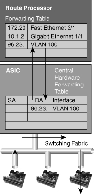
![]() CEF uses special strategies to switch data packets to their destinations expediently. It caches the information generated by the Layer 3 routing engine even before the switch encounters any data flows. CEF caches routing information in one table (the FIB) and caches Layer 2 next-hop addresses and frame header rewrite information for all FIB entries in another table, called the adjacency table (AT), as shown in Figure 4-22.
CEF uses special strategies to switch data packets to their destinations expediently. It caches the information generated by the Layer 3 routing engine even before the switch encounters any data flows. CEF caches routing information in one table (the FIB) and caches Layer 2 next-hop addresses and frame header rewrite information for all FIB entries in another table, called the adjacency table (AT), as shown in Figure 4-22.


![]() As illustrated in Figure 4-22, CEF separates the control plane hardware from the data plane hardware and switching. ASICs in switches are used to separate the control plane and data plane, thereby achieving higher data throughput. The control plane is responsible for building the FIB table and adjacency tables in software. The data plane is responsible for forwarding IP unicast traffic using hardware.
As illustrated in Figure 4-22, CEF separates the control plane hardware from the data plane hardware and switching. ASICs in switches are used to separate the control plane and data plane, thereby achieving higher data throughput. The control plane is responsible for building the FIB table and adjacency tables in software. The data plane is responsible for forwarding IP unicast traffic using hardware.
![]() The following is a summary of these tables:
The following is a summary of these tables:
- FIB: Derived from the IP routing table and arranged for maximum lookup throughput. CEF IP destination prefixes are stored in the TCAM table, from the most-specific to the least-specific entry. The FIB lookup is based on the Layer 3 destination address prefix (longest match), so it matches the structure of CEF entries within the TCAM. When the CEF TCAM table is full, a wildcard entry redirects frames to the Layer 3 engine. The FIB table is updated after each network change but only once and contains all known routes—there is no need to build a route-cache by central processing initial packets from each data flow. Each change in the IP routing table triggers a similar change in the FIB table because it contains all next-hop addresses associated with all destination networks.
- AT: The adjacency table is derived from the ARP table and contains Layer 2 header rewrite (MAC) information for each next hop contained in the FIB. Nodes in the network are said to be adjacent if they are within a single hop from each other. The adjacency table maintains Layer 2 next-hop addresses and link-layer header information for all FIB entries. The adjacency table is populated as adjacencies are discovered. Each time an adjacency entry is created (such as through the ARP protocol), a link-layer header for that adjacent node is precomputed and stored in the adjacency table. When the adjacency table is full, a CEF TCAM table entry points to the Layer 3 engine to redirect the adjacency.
![]() The following types of adjacencies exist for special processing:
The following types of adjacencies exist for special processing:
- Punt adjacency: Used for packets that require special handling by the Layer 3 engine or for features that are not yet supported by hardware switching.
- Drop or discard adjacency: Used to drop ingress packets.
- Null adjacency: Used to drop packets destined for a Null0 interface. The use of a Null0 interface is for access filtering of specific source IP packets.
![]() Not all packets can be processed in the hardware. When traffic cannot be processed in the hardware, it must receive software processing by the Layer 3 engine. This traffic does not receive the benefit of expedited hardware-based forwarding. A number of different packet types might force the Layer 3 engine to process them. Some examples of IP exception packets follow:
Not all packets can be processed in the hardware. When traffic cannot be processed in the hardware, it must receive software processing by the Layer 3 engine. This traffic does not receive the benefit of expedited hardware-based forwarding. A number of different packet types might force the Layer 3 engine to process them. Some examples of IP exception packets follow:
- Use IP header options (Packets that use TCP header options are switched in hardware because they do not affect the forwarding decision.)
- Have an expiring IP Time-To-Live (TTL) counter
- Are forwarded to a tunnel interface
- Arrive with nonsupported encapsulation types
- Are routed to an interface with nonsupported encapsulation types
- Exceed the maximum transmission unit (MTU) of an output interface and must be fragmented
![]() Some Cisco switches actually use different hardware to control the different planes. For example, the Cisco Catalyst 6500 is a modular switch that uses the Multilayer Switch Feature Card (MSFC) for control-plane operations, and the supervisor Policy Feature Card (PFC) for the data-plane operations.
Some Cisco switches actually use different hardware to control the different planes. For example, the Cisco Catalyst 6500 is a modular switch that uses the Multilayer Switch Feature Card (MSFC) for control-plane operations, and the supervisor Policy Feature Card (PFC) for the data-plane operations.
CEF Operation and Use of TCAM
![]() The following list details the characteristics of CEF operation and its use of the TCAM:
The following list details the characteristics of CEF operation and its use of the TCAM:
- Longest-match lookups in the FIB table are done for the Layer 3 destination address prefixes.
- CEF uses the IP routing table on the Layer 3 forwarding engine to build the FIB. Arrangement of the FIB is for maximum lookup throughput.
- CEF builds the adjacency table from the ARP table. The adjacency table contains Layer 2 rewrite (MAC) information for the next hop.
- FIB entries in the TCAM table are populated from the most specific to the least specific entry.
- Adjacency (rewrite) information and statistics are maintained by specialized components.
- CEF maintains one-to-one CEF-to-adjacency mappings for accurate statistics tracking.
- When the FIB table in TCAM is full, a wildcard entry redirects unmatched entries to the software switching Layer 3 forwarding engine.
- When the adjacency table in TCAM is full, an entry in the FIB table points to the Layer 3 forwarding engine to redirect the adjacency lookup.
- FIB and adjacency tables are dynamically updated when an ARP entry for a destination next hop changes, ages out, or is removed; the routing table changes; or next-hop rewrite information changes.
CEF Modes of Operation
![]() As previously discussed in detail in the “Topology-Based Routing” section, CEF operates in one of two modes.
As previously discussed in detail in the “Topology-Based Routing” section, CEF operates in one of two modes.
- Central CEF mode: The CEF FIB and adjacency tables reside on the route processor, and the route processor performs the express forwarding. Use this CEF mode when line cards are not available for CEF switching, or when features are not compatible with distributed CEF.
- Distributed Cisco Express Forwarding (dCEF) mode: When dCEF is enabled, line cards maintain identical copies of the FIB and adjacency tables. The line cards can perform the express forwarding by themselves, relieving the main processor of involvement in the switching operation. dCEF uses an interprocess communications (IPC) mechanism to ensure synchronization of FIBs and adjacency tables on the route processor and line cards.
Address Resolution Protocol Throttling
![]() An important feature of CEF-based Catalyst switches is Address Resolution Protocol (ARP) throttling; this feature requires explanation before CEF-based MLS is explored further. Make note that the ARP table builds the CEF adjacency table. This concept is explored in more detail throughout this chapter; however, it is important to consider when reading this section.
An important feature of CEF-based Catalyst switches is Address Resolution Protocol (ARP) throttling; this feature requires explanation before CEF-based MLS is explored further. Make note that the ARP table builds the CEF adjacency table. This concept is explored in more detail throughout this chapter; however, it is important to consider when reading this section.
![]() When a router is directly connected to a segment shared by multiple hosts such as Ethernet interfaces, the router maintains an additional prefix for the subnet. This subnet prefix points to a glean adjacency. When a router receives packets that need to be forwarded to a specific host, the adjacency database is gleaned for the specific prefix. If the prefix does not exist, the subnet prefix is consulted, and the glean adjacency indicates that any addresses within this range should be forwarded to the Layer 3 engine ARP processing.
When a router is directly connected to a segment shared by multiple hosts such as Ethernet interfaces, the router maintains an additional prefix for the subnet. This subnet prefix points to a glean adjacency. When a router receives packets that need to be forwarded to a specific host, the adjacency database is gleaned for the specific prefix. If the prefix does not exist, the subnet prefix is consulted, and the glean adjacency indicates that any addresses within this range should be forwarded to the Layer 3 engine ARP processing.
![]() One example where glean adjacencies are used is where a Catalyst switch receives a packet for which no rewrite information exists. To obtain rewrite information, the Layer 3 engine sends ARP requests to next hop to obtain the rewrite information. Catalyst switches using CEF-based MLS forward only the first several packets to the Layer 3 engine for new destinations without rewrite information. The switch installs a throttling adjacency such that the switch drops subsequent packets to the specific destination address in hardware until an ARP response is received. The switch removes the throttling adjacency when an ARP reply is received from the Layer 3 engine (and a complete rewrite adjacency is installed for the host). The switch removes the throttling adjacency if no ARP reply is seen within 2 seconds (to enable more packets through to the Layer 3 engine to reinitiate ARP). This relieves the Layer 3 engine from excessive ARP processing (or ARP-based denial-of-service [DoS] attacks).
One example where glean adjacencies are used is where a Catalyst switch receives a packet for which no rewrite information exists. To obtain rewrite information, the Layer 3 engine sends ARP requests to next hop to obtain the rewrite information. Catalyst switches using CEF-based MLS forward only the first several packets to the Layer 3 engine for new destinations without rewrite information. The switch installs a throttling adjacency such that the switch drops subsequent packets to the specific destination address in hardware until an ARP response is received. The switch removes the throttling adjacency when an ARP reply is received from the Layer 3 engine (and a complete rewrite adjacency is installed for the host). The switch removes the throttling adjacency if no ARP reply is seen within 2 seconds (to enable more packets through to the Layer 3 engine to reinitiate ARP). This relieves the Layer 3 engine from excessive ARP processing (or ARP-based denial-of-service [DoS] attacks).
![]() Figure 4-23 shows an example of ARP throttling; an explanation of its stepwise behavior follows. Figure 4-23 depicts the Layer 3 forwarding engine and hardware switching forwarding engine as two separate hardware components for illustrative purposes.
Figure 4-23 shows an example of ARP throttling; an explanation of its stepwise behavior follows. Figure 4-23 depicts the Layer 3 forwarding engine and hardware switching forwarding engine as two separate hardware components for illustrative purposes.


![]() ARP throttling consists of the following steps:
ARP throttling consists of the following steps:
|
|
|
|
|
|
|
|
|
|
|
|
|
|
|
![]() Figure 4-24, later in this chapter using the same example as in Figure 4-23, shows stepwise how the packet is routed in a multilayer switch using CEF in a larger context.
Figure 4-24, later in this chapter using the same example as in Figure 4-23, shows stepwise how the packet is routed in a multilayer switch using CEF in a larger context.


Sample CEF-Based MLS Operation
![]() Before a multilayer switch can route frames in the hardware, it sets up the necessary routing information in the hardware. After the switch has set up the necessary routing information in the hardware, frame routing in the hardware can start. Figure 4-24 illustrates the steps for how a frame is routed in a multilayer switch using CEF.
Before a multilayer switch can route frames in the hardware, it sets up the necessary routing information in the hardware. After the switch has set up the necessary routing information in the hardware, frame routing in the hardware can start. Figure 4-24 illustrates the steps for how a frame is routed in a multilayer switch using CEF.
![]() These steps assume the switch does not initially have rewrite information for the destination:
These steps assume the switch does not initially have rewrite information for the destination:
| Note |
|
CEF-Based MLS Load Sharing
![]() CEF does support load sharing (equal-cost or nonequal-cost). However, CEF does not support all the load-sharing features found in software-based CEF. With the current version of software on a Catalyst 6500 switch, a single FIB entry may have up to six adjacencies for load sharing per destination.
CEF does support load sharing (equal-cost or nonequal-cost). However, CEF does not support all the load-sharing features found in software-based CEF. With the current version of software on a Catalyst 6500 switch, a single FIB entry may have up to six adjacencies for load sharing per destination.
![]() To achieve evenly distributed load balancing across multiple interfaces, CEF selects a particular adjacency based on the hash (mathematical equivalent) of the following packet characteristics:
To achieve evenly distributed load balancing across multiple interfaces, CEF selects a particular adjacency based on the hash (mathematical equivalent) of the following packet characteristics:
- Source IP address
- Destination IP address
- Source and destination IP Layer 4 ports
![]() In addition, parallel paths can exist and enable CEF to perform load balancing. Per-destination load balancing enables the Layer 3 switch to use multiple paths to achieve load sharing for packets going to different destinations. Packets for a given source-destination host pair are guaranteed to take the same path, even if multiple paths are available. This ensures that packets for a given host pair arrive in order. Per-destination load balancing is enabled by default when you allow CEF, and it is the load balancing method of choice for most situations.
In addition, parallel paths can exist and enable CEF to perform load balancing. Per-destination load balancing enables the Layer 3 switch to use multiple paths to achieve load sharing for packets going to different destinations. Packets for a given source-destination host pair are guaranteed to take the same path, even if multiple paths are available. This ensures that packets for a given host pair arrive in order. Per-destination load balancing is enabled by default when you allow CEF, and it is the load balancing method of choice for most situations.
![]() However, this is also a potential limitation of CEF. Because CEF by default would always select the same path for a given host pair, in a topology with multiple Layer 3 paths between a given host pair, where packet-based load balancing would normally occur across the multiple paths, CEF “polarizes” the traffic by using only one path for a given host pair, thus effectively negating the load balancing benefit of the multiple paths for that particular host pair.
However, this is also a potential limitation of CEF. Because CEF by default would always select the same path for a given host pair, in a topology with multiple Layer 3 paths between a given host pair, where packet-based load balancing would normally occur across the multiple paths, CEF “polarizes” the traffic by using only one path for a given host pair, thus effectively negating the load balancing benefit of the multiple paths for that particular host pair.
![]() Because per-destination load balancing depends on the statistical distribution of traffic, load sharing becomes more effective as the number of source-destination pairs increases. Thus, in an environment where there is a broad distribution of traffic among host pairs, CEF polarization is of minimal concern. However, in an environment where data flow between a small number of host pairs creates a disproportionate percentage of the packets traversing the network, CEF polarization can become a serious problem. CEF load balancing can be “tuned,” so a network engineer who anticipates a problem with CEF polarization would want to ensure that such tuning was performed within the enterprise network.
Because per-destination load balancing depends on the statistical distribution of traffic, load sharing becomes more effective as the number of source-destination pairs increases. Thus, in an environment where there is a broad distribution of traffic among host pairs, CEF polarization is of minimal concern. However, in an environment where data flow between a small number of host pairs creates a disproportionate percentage of the packets traversing the network, CEF polarization can become a serious problem. CEF load balancing can be “tuned,” so a network engineer who anticipates a problem with CEF polarization would want to ensure that such tuning was performed within the enterprise network.
![]() The default load-sharing method and hashing algorithms vary slightly per Catalyst switch family. Consult the product documentation for specifics about load-sharing support on each Catalyst switch.
The default load-sharing method and hashing algorithms vary slightly per Catalyst switch family. Consult the product documentation for specifics about load-sharing support on each Catalyst switch.
Configuring CEF and Verifying CEF Configuration
![]() This section discusses how to configure and verify CEF.
This section discusses how to configure and verify CEF.
CEF-Based MLS Configuration
![]() Cisco Catalyst switches that use the CEF-based MLS architecture use CEF by default. For Catalyst switches that support CEF-based MLS, CEF and per-destination load balancing with CEF are enabled by default. As a result, no configuration is required for CEF-based MLS.
Cisco Catalyst switches that use the CEF-based MLS architecture use CEF by default. For Catalyst switches that support CEF-based MLS, CEF and per-destination load balancing with CEF are enabled by default. As a result, no configuration is required for CEF-based MLS.
![]() Network administrators should not disable CEF on Catalyst switches for any reason except under the supervision of a Cisco TAC engineer for the specific purpose of troubleshooting. Disabling CEF on Cisco Catalyst switches yields low switching performance and can result in undesirable behavior.
Network administrators should not disable CEF on Catalyst switches for any reason except under the supervision of a Cisco TAC engineer for the specific purpose of troubleshooting. Disabling CEF on Cisco Catalyst switches yields low switching performance and can result in undesirable behavior.
CEF-Based MLS Verification
![]() To verify the CEF information, use the following commands to help verify any issues with CEF:
To verify the CEF information, use the following commands to help verify any issues with CEF:
- show interface type number: Provides stats for hardware switching Layer 3 packets
- show ip cef: Verifies the FIB
- show ip cef [type mod/port | vlan_interface] [detail]: Verifies the detailed information about a particular vlan or interface
- show adjacency type mod/port | port-channel number} | detail | internal | summary: Verifies adjacency table
![]() Example 4-11 shows the output of show interface commands. In Example 4-11, the lines beginning L2 Switched, L3 in Switched, and L3 out Switched indicate the Layer 3 hardware-switching statistics. Catalyst switches do not instantaneously update hardware-switching statistics for CLI show commands. For example, on the Catalyst 4500 family of switches running Cisco IOS, interface statistics might take up to 30 seconds to be updated in show commands. Furthermore, each Catalyst family of switches has its own troubleshooting methodology and commands for viewing hardware switching statistics. Consult Cisco.com for more details.
Example 4-11 shows the output of show interface commands. In Example 4-11, the lines beginning L2 Switched, L3 in Switched, and L3 out Switched indicate the Layer 3 hardware-switching statistics. Catalyst switches do not instantaneously update hardware-switching statistics for CLI show commands. For example, on the Catalyst 4500 family of switches running Cisco IOS, interface statistics might take up to 30 seconds to be updated in show commands. Furthermore, each Catalyst family of switches has its own troubleshooting methodology and commands for viewing hardware switching statistics. Consult Cisco.com for more details.
Port-channel9 is up, line protocol is up (connected)
Hardware is EtherChannel, address is 00d0.039b.e80a (bia 00d0.039b.e800)
Description: POINT-TO-POINT TO CORE-4
! Output omitted for brevity
Output queue: 0/40 (size/max)
5 minute input rate 0 bits/sec, 0 packets/sec
5 minute output rate 0 bits/sec, 0 packets/sec
L2 Switched: ucast: 205744 pkt, 34282823 bytes - mcast: 216245 pkt, 66357101
bytes
L3 in Switched: ucast: 367825 pkt, 361204150 bytes - mcast: 0 pkt, 0 bytes mcast
L3 out Switched: ucast: 248325 pkt, 243855150 bytes
682964 packets input, 431530341 bytes, 0 no buffer
Received 311465 broadcasts (50899 IP multicast)
0 runts, 0 giants, 0 throttles
0 input errors, 0 CRC, 0 frame, 0 overrun, 0 ignored
0 watchdog, 0 multicast, 0 pause input
0 input packets with dribble condition detected
554167 packets output, 309721969 bytes, 0 underruns
0 output errors, 0 collisions, 8 interface resets
0 babbles, 0 late collision, 0 deferred
0 lost carrier, 0 no carrier, 0 PAUSE output
0 output buffer failures, 0 output buffers swapped out
![]() The Layer 3 Engine CEF table determines the hardware-switching CEF table. As such, when troubleshooting any CEF issues, the first step is to view the software CEF table. You can use the show ip cef command to display information about entries in the FIB. Example 4-12 output shows only general information about entries in the FIB, such as the destination network address, associated interface, and next hop (or local action, such as drop).
The Layer 3 Engine CEF table determines the hardware-switching CEF table. As such, when troubleshooting any CEF issues, the first step is to view the software CEF table. You can use the show ip cef command to display information about entries in the FIB. Example 4-12 output shows only general information about entries in the FIB, such as the destination network address, associated interface, and next hop (or local action, such as drop).
Prefix Next Hop Interface
0.0.0.0/32 receive
1.0.0.0/24 attached GigabitEthernet0/2
1.0.0.0/32 receive
1.0.0.1/32 receive
1.0.0.55/32 1.0.0.55 GigabitEthernet0/2
![]() In addition, the show ip cef command with a detail option for a particular port or interface provides additional information. The output shows that CEF is enabled and various statistics about the number of routes and how many have been added or removed from the FIB. Example 4-13 shows that SVI VLAN 10 connects directly to the 10.1.10.0 network because it has a glean adjacency associated with that network. Recall that a glean adjacency is in the CEF adjacency table when multiple hosts are directly connected to the multilayer switch through a single port or interface.
In addition, the show ip cef command with a detail option for a particular port or interface provides additional information. The output shows that CEF is enabled and various statistics about the number of routes and how many have been added or removed from the FIB. Example 4-13 shows that SVI VLAN 10 connects directly to the 10.1.10.0 network because it has a glean adjacency associated with that network. Recall that a glean adjacency is in the CEF adjacency table when multiple hosts are directly connected to the multilayer switch through a single port or interface.
IP CEF with switching (Table Version 11), flags=0x0
10 routes, 0 reresolve, 0 unresolved (0 old, 0 new), peak 0
13 leaves, 12 nodes, 14248 bytes, 14 inserts, 1 invalidations
0 load sharing elements, 0 bytes, 0 references
universal per-destination load sharing algorithm, id 4B936A24
2(0) CEF resets, 0 revisions of existing leaves
Resolution Timer: Exponential (currently 1s, peak 1s)
0 in-place/0 aborted modifications
refcounts: 1061 leaf, 1052 node
Table epoch: 0 (13 entries at this epoch)
10.1.10.0/24, version 6, epoch 0, attached, connected
0 packets, 0 bytes
via Vlan10, 0 dependencies
valid glean adjacency
![]() CEF populates the adjacency tables when MAC addresses are learned via the ARP process. As a result, the adjacency table includes the MAC address rewrite information and destination interface for the adjacent node. All IP routing entries in the CEF table correspond to a next-hop address (adjacency).
CEF populates the adjacency tables when MAC addresses are learned via the ARP process. As a result, the adjacency table includes the MAC address rewrite information and destination interface for the adjacent node. All IP routing entries in the CEF table correspond to a next-hop address (adjacency).
![]() When a switch hardware-switches an ingress packet with the destination MAC address as itself, it looks up the destination IP address in the CEF table. The first match in the CEF table points to an adjacency entry that contains the MAC rewrite information and destination interface. The switch rewrites the packet accordingly and sends it out the destination interface.
When a switch hardware-switches an ingress packet with the destination MAC address as itself, it looks up the destination IP address in the CEF table. The first match in the CEF table points to an adjacency entry that contains the MAC rewrite information and destination interface. The switch rewrites the packet accordingly and sends it out the destination interface.
![]() A single CEF entry might point to multiple adjacency entries when multiple paths to a destination exist. In addition, when a router is connected directly to several hosts, the FIB table on the router maintains a prefix for the subnet rather than for the individual host prefixes. The subnet prefix points to a glean adjacency. When packets need to be forwarded to a specific host, the adjacency database is gleaned for the specific prefix.
A single CEF entry might point to multiple adjacency entries when multiple paths to a destination exist. In addition, when a router is connected directly to several hosts, the FIB table on the router maintains a prefix for the subnet rather than for the individual host prefixes. The subnet prefix points to a glean adjacency. When packets need to be forwarded to a specific host, the adjacency database is gleaned for the specific prefix.
![]() Certain IP prefixes or addresses require exception processing. Switches require exception processing of packets when hardware switching does not support routing of the frame or when the Layer 3 engine requires processing of the packet. Examples of packets that require exception processing include interfaces configured for NAT and received packets with IP options.
Certain IP prefixes or addresses require exception processing. Switches require exception processing of packets when hardware switching does not support routing of the frame or when the Layer 3 engine requires processing of the packet. Examples of packets that require exception processing include interfaces configured for NAT and received packets with IP options.
![]() To display adjacency table information, use the show adjacency command. Example 4-14 shows the adjacency summary.
To display adjacency table information, use the show adjacency command. Example 4-14 shows the adjacency summary.
Protocol Interface Address
IP GigabitEthernet0/3 2.0.0.55(5)
IP GigabitEthernet0/2 1.0.0.55(5)
![]() Example 4-15 displays the adjacency table in more detailed.
Example 4-15 displays the adjacency table in more detailed.
Protocol Interface Address
IP GigabitEthernet1/5 172.20.53.206(11)
504 packets, 6110 bytes
00605C865B82
000164F83FA50800
ARP 03:49:31
| Note |
|
![]() In addition, the show cef drops command displays an indication of packets that are being dropped due to adjacencies that are either incomplete or nonexistent. The symptoms of an incomplete adjacency include random packet drops during a ping test. Following are two known reasons for incomplete or nonexistent adjacencies:
In addition, the show cef drops command displays an indication of packets that are being dropped due to adjacencies that are either incomplete or nonexistent. The symptoms of an incomplete adjacency include random packet drops during a ping test. Following are two known reasons for incomplete or nonexistent adjacencies:
Troubleshooting CEF
![]() In terms of troubleshooting, understanding the basic operation of multilayer switches is paramount; multilayer switching requires a hierarchical approach to troubleshooting because several switching components determine the packet flow, not a single processing engine. CEF-based MLS configuration, verification, and troubleshooting vary slightly per Catalyst switch family but do have some commonalities.
In terms of troubleshooting, understanding the basic operation of multilayer switches is paramount; multilayer switching requires a hierarchical approach to troubleshooting because several switching components determine the packet flow, not a single processing engine. CEF-based MLS configuration, verification, and troubleshooting vary slightly per Catalyst switch family but do have some commonalities.
![]() Previous subsections discussed several CEF troubleshooting techniques on the Layer 3 engine. Recall that the Layer 3 engine does not actually contain the hardware FIB and adjacency table. Instead, these tables are located in specialized hardware components in supervisor engines and line cards. The following highlights a stepwise approach to troubleshooting a unicast route on a CEF-based Catalyst switch. The troubleshooting steps are not inclusive but do review the hierarchical approach to troubleshooting CEF-based MLS:
Previous subsections discussed several CEF troubleshooting techniques on the Layer 3 engine. Recall that the Layer 3 engine does not actually contain the hardware FIB and adjacency table. Instead, these tables are located in specialized hardware components in supervisor engines and line cards. The following highlights a stepwise approach to troubleshooting a unicast route on a CEF-based Catalyst switch. The troubleshooting steps are not inclusive but do review the hierarchical approach to troubleshooting CEF-based MLS:
|
|
|
|
|
|
|
|
|
|
|
|
|
|
|
Summary
![]() This chapter discussed in detail Layer 3 routing and its implementation, including coverage of inter-VLAN routing and router-on-a-stick, DHCP services, and the forwarding path of multilayer switching using CEF. This chapter can be summarized as follows:
This chapter discussed in detail Layer 3 routing and its implementation, including coverage of inter-VLAN routing and router-on-a-stick, DHCP services, and the forwarding path of multilayer switching using CEF. This chapter can be summarized as follows:
- Inter-VLAN routing provides communication between the devices in different VLANs. Recall that a VLAN is a single broadcast domain, and the devices within a VLAN cannot communicate beyond VLAN boundaries unless through a Layer 3 device. Multilayer switches support two types of Layer 3 interfaces: routed ports and SVIs (VLAN interfaces).
- Routed ports are point-to-point connections such as those that interconnect the building distribution submodules and the campus backbone submodules when using Layer 3 in the distribution layer.
- SVIs are VLAN interfaces that route traffic between VLANs and VLAN group ports. In multilayer switched networks with Layer 3 in the distribution layer and Layer 2 in the access layer, SVIs can route traffic from VLANs on the access-layer switches.
- Using router-on-a -stick is an alternative and legacy method of implementing inter-VLAN routing for low-throughput and latency-tolerant applications.
- On multilayer switches, Layer 3 links can be aggregated using Layer 3 EtherChannels. When a Layer 3 interface is configured, routing can be enabled.
- DHCP functions can be configured on the switches.
- Multilayer switches can forward traffic based on either Layer 2 or Layer 3 header information. Multilayer switches rewrite frame and packet headers using information from tables cached in hardware. Layer 3 (multilayer) switching is high-performance packet switching in hardware. Multilayer switching can use centralized or distributed switching, and route caching or topology-based switching. Multilayer switching functionality can be implemented using Cisco Express Forwarding (CEF), which utilizes two tables in hardware to forward packets: a Forwarding Information Base (FIB) and an Adjacency Table (AT).
1 comments
What a great article!!! Very well define…
visit : http://networkexpert.co/
Post a Comment