
Transitioning IPv4 to IPv6
![]() The successful market adoption of any new technology depends on its easy integration with the existing infrastructure without significant disruption of services. The Internet consists of hundreds of thousands of IPv4 networks and millions of IPv4 nodes. The challenge for IPv6 lies in making the integration of IPv4 and IPv6 nodes and the transition to IPv6 as transparent as possible to end users. From renumbering, to router upgrades, to protocol conversion, to client support, many different techniques are needed to ensure a smooth transition.
The successful market adoption of any new technology depends on its easy integration with the existing infrastructure without significant disruption of services. The Internet consists of hundreds of thousands of IPv4 networks and millions of IPv4 nodes. The challenge for IPv6 lies in making the integration of IPv4 and IPv6 nodes and the transition to IPv6 as transparent as possible to end users. From renumbering, to router upgrades, to protocol conversion, to client support, many different techniques are needed to ensure a smooth transition.
![]() Fortunately, the transition from IPv4 to IPv6 does not require upgrades on all nodes at the same time; IPv4 and IPv6 will coexist for some time. Many RFCs relate to this transition, including those listed in Table 8-15.
Fortunately, the transition from IPv4 to IPv6 does not require upgrades on all nodes at the same time; IPv4 and IPv6 will coexist for some time. Many RFCs relate to this transition, including those listed in Table 8-15.
|
|
|
|---|---|
|
|
|
|
|
|
|
|
|
|
|
|
|
|
|
|
|
|
|
|
|
|
|
|
|
|
|
|
|
|
|
|
|
|
|
|
|
|
|
|
|
|
![]() A wide range of techniques are available for the period of transition between IPv4 and IPv6. These techniques can be grouped into the following three categories:
A wide range of techniques are available for the period of transition between IPv4 and IPv6. These techniques can be grouped into the following three categories:
-
 Dual-stack techniques— Hosts and network devices run both IPv4 and IPv6 at the same time. This technique is useful as a temporary transition, but it adds overhead and uses many resources.
 - Tunneling techniques— Isolated IPv6 networks are connected over an IPv4 infrastructure using tunnels. The edge devices are the only ones that need to be dual-stacked. Scalability may be an issue if many tunnels need to be created.
- Translation techniques— A translation device converts IPv6 packets into IPv4 packets and vise versa, allowing IPv6-only devices to communicate with IPv4-only devices. Scalability may again be an issue because of the resources required on the translator device.
![]() The following sections provide a brief overview of each of these techniques. Later sections in this chapter detail some of the many tunneling and translation techniques.
The following sections provide a brief overview of each of these techniques. Later sections in this chapter detail some of the many tunneling and translation techniques.
Dual Stack
![]() Dual stack is one of the primary technologies that makes the transition to IPv6 possible. It is an integration method in which a node has connectivity to both an IPv4 and IPv6 network; the node has two protocol stacks. The two stacks can be on the same interface or on multiple interfaces.
Dual stack is one of the primary technologies that makes the transition to IPv6 possible. It is an integration method in which a node has connectivity to both an IPv4 and IPv6 network; the node has two protocol stacks. The two stacks can be on the same interface or on multiple interfaces.
![]() A dual-stack node chooses which stack to use based on the destination address; the node should prefer IPv6 when available. The dual-stack approach to IPv6 integration will be one of the most commonly used methods. Old IPv4-only applications will continue to work as before, while new and modified applications take advantage of both IP layers.
A dual-stack node chooses which stack to use based on the destination address; the node should prefer IPv6 when available. The dual-stack approach to IPv6 integration will be one of the most commonly used methods. Old IPv4-only applications will continue to work as before, while new and modified applications take advantage of both IP layers.
![]() Application authors can add a new application programming interface (API) that supports both IPv4 and IPv6 addresses and Domain Name System (DNS) requests. Converted applications will be able to make use of both IPv4 and IPv6. An application can be converted to the new API while still using only IPv4.
Application authors can add a new application programming interface (API) that supports both IPv4 and IPv6 addresses and Domain Name System (DNS) requests. Converted applications will be able to make use of both IPv4 and IPv6. An application can be converted to the new API while still using only IPv4.
![]() Cisco IOS Software is IPv6 ready: As soon as IPv4 and IPv6 configurations are complete on an interface, the interface is dual stacked and it forwards both IPv4 and IPv6 traffic.
Cisco IOS Software is IPv6 ready: As soon as IPv4 and IPv6 configurations are complete on an interface, the interface is dual stacked and it forwards both IPv4 and IPv6 traffic.
![]() Consider the simple network in Figure 8-38. When R1 is configured with the commands shown in Example 8-98, it is dual stacked. Notice that the Fast Ethernet 0/0 interface has two addresses on it, an IPv4 and an IPv6 address. Also notice that for each protocol, the addresses on R1 and R2 are on the same network. The example also shows commands used to verify the configuration. The show ip interface command verifies the IPv4 configuration on the interface, and the show ipv6 interface command verifies the IPv6 configuration on the interface.
Consider the simple network in Figure 8-38. When R1 is configured with the commands shown in Example 8-98, it is dual stacked. Notice that the Fast Ethernet 0/0 interface has two addresses on it, an IPv4 and an IPv6 address. Also notice that for each protocol, the addresses on R1 and R2 are on the same network. The example also shows commands used to verify the configuration. The show ip interface command verifies the IPv4 configuration on the interface, and the show ipv6 interface command verifies the IPv6 configuration on the interface.
R1(config-if)#ip address 10.10.10.1 255.255.255.0
R1(config-if)#ipv6 address 2001:12::1/64
R1(config-if)#^Z
R1#show ip interface fa0/0
FastEthernet0/0 is up, line protocol is up
Internet address is 10.10.10.1/24
Broadcast address is 255.255.255.255
Address determined by setup command
MTU is 1500 bytes
Helper address is not set
Directed broadcast forwarding is disabled
Outgoing access list is not set
Inbound access list is not set
Proxy ARP is enabled
Local Proxy ARP is disabled
Security level is default
Split horizon is enabled
ICMP redirects are always sent
ICMP unreachables are always present
![]() A drawback of dual stacking is the resources required within each device configured with both protocols. The device must keep dual routing tables, routing protocol topology tables, and so forth, and must process each protocol independently. There is also a higher administrative overhead, and troubleshooting, monitoring, and so on is more complex.
A drawback of dual stacking is the resources required within each device configured with both protocols. The device must keep dual routing tables, routing protocol topology tables, and so forth, and must process each protocol independently. There is also a higher administrative overhead, and troubleshooting, monitoring, and so on is more complex.
Tunneling
![]() Tunnels are often used in networking to overlay incompatible functions over an existing network. For IPv6, tunneling is an integration method in which an IPv6 packet is encapsulated within IPv4.
Tunnels are often used in networking to overlay incompatible functions over an existing network. For IPv6, tunneling is an integration method in which an IPv6 packet is encapsulated within IPv4.
![]() When tunneling IPv6 traffic over an IPv4 network, an edge device (such as a router) encapsulates the IPv6 packet inside an IPv4 packet and the device at the other edge decapsulates it, and vice versa. This enables the connection of IPv6 islands without the need to convert the intermediary network to IPv6.
When tunneling IPv6 traffic over an IPv4 network, an edge device (such as a router) encapsulates the IPv6 packet inside an IPv4 packet and the device at the other edge decapsulates it, and vice versa. This enables the connection of IPv6 islands without the need to convert the intermediary network to IPv6.
![]() An example is illustrated in Figure 8-39. The routers involved in this example are dual stacking.
An example is illustrated in Figure 8-39. The routers involved in this example are dual stacking.


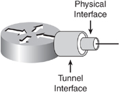
![]() Tunneling can also be done between a host and a router, as shown in Figure 8-40, where an isolated dual-stack host uses an encapsulated tunnel to connect to the edge router of the IPv6 network.
Tunneling can also be done between a host and a router, as shown in Figure 8-40, where an isolated dual-stack host uses an encapsulated tunnel to connect to the edge router of the IPv6 network.


![]() Tunnels can be either manually or automatically configured, depending on the scale required and administrative overhead tolerated.
Tunnels can be either manually or automatically configured, depending on the scale required and administrative overhead tolerated.
![]() Figure 8-41 illustrates another tunnel example, with addressing shown. Tunnels are typically created between loopback addresses on the edge routers, for stability. Notice that the physical interfaces connected to the IPv4 network have IPv4 addresses, as do the loopback interfaces. Also notice that the R1 and R2 addresses on the IPv4 network are on different subnets because they are not directly connected. However, the IPv6 addresses on the tunnel are on the same IPv6 network because the tunnel is a virtual point-to-point IPv6 connection between the two routers. The tunnel is an IPv6 link that is not concerned with the complexity of the IPv4 network over which it runs.
Figure 8-41 illustrates another tunnel example, with addressing shown. Tunnels are typically created between loopback addresses on the edge routers, for stability. Notice that the physical interfaces connected to the IPv4 network have IPv4 addresses, as do the loopback interfaces. Also notice that the R1 and R2 addresses on the IPv4 network are on different subnets because they are not directly connected. However, the IPv6 addresses on the tunnel are on the same IPv6 network because the tunnel is a virtual point-to-point IPv6 connection between the two routers. The tunnel is an IPv6 link that is not concerned with the complexity of the IPv4 network over which it runs.


![]() Some tunneling terminology can be explained using this example:
Some tunneling terminology can be explained using this example:
- IPv4 is the transport protocol, the protocol over which the tunnel is created.
- IPv6 is the passenger protocol, the protocol encapsulated in the tunnel and carried through the tunnel.
- Another protocol is used to create the tunnel, and is known as the tunneling protocol. It is also called the encapsulation protocol or the carrier protocol. An example of such a protocol is the Cisco generic routing encapsulation (GRE) protocol. It encapsulates the passenger protocol.
![]() Tunneling is described further in the upcoming “Tunneling IPv6 Traffic” section.
Tunneling is described further in the upcoming “Tunneling IPv6 Traffic” section.
Translation
![]() The dual-stack and tunneling techniques manage the interconnection of IPv6 domains. For legacy equipment that will not be upgraded to IPv6 and for some deployment scenarios, techniques are available for connecting IPv4-only nodes to IPv6-only nodes, using translation, an extension of NAT techniques.
The dual-stack and tunneling techniques manage the interconnection of IPv6 domains. For legacy equipment that will not be upgraded to IPv6 and for some deployment scenarios, techniques are available for connecting IPv4-only nodes to IPv6-only nodes, using translation, an extension of NAT techniques.
![]() As shown in Figure 8-42, NAT-PT is a translation mechanism that sits between an IPv6 network and an IPv4 network. The job of the translator (which, of course, can be a Cisco IOS router) is to translate IPv6 packets into IPv4 packets and vice versa. It is more than an address translator, it is really a protocol translator.
As shown in Figure 8-42, NAT-PT is a translation mechanism that sits between an IPv6 network and an IPv4 network. The job of the translator (which, of course, can be a Cisco IOS router) is to translate IPv6 packets into IPv4 packets and vice versa. It is more than an address translator, it is really a protocol translator.


| Note |
|
![]() The example in Figure 8-42 illustrates the translation of an IPv6 datagram sent from node A to node D. From the perspective of node A, it is establishing a communication to another IPv6 node. One advantage of NAT-PT is that no modifications are required on IPv6 node A; all it needs to know is the IPv6 address mapping of the IPv4 address of node D. This mapping can be obtained dynamically from the DNS server. IPv4 node D can also send a datagram to node A by using the IPv4 address mapped to the IPv6 address of node A. Again, from the perspective of node D, it is establishing IPv4 communication with node A. Node D does not require modification.
The example in Figure 8-42 illustrates the translation of an IPv6 datagram sent from node A to node D. From the perspective of node A, it is establishing a communication to another IPv6 node. One advantage of NAT-PT is that no modifications are required on IPv6 node A; all it needs to know is the IPv6 address mapping of the IPv4 address of node D. This mapping can be obtained dynamically from the DNS server. IPv4 node D can also send a datagram to node A by using the IPv4 address mapped to the IPv6 address of node A. Again, from the perspective of node D, it is establishing IPv4 communication with node A. Node D does not require modification.
![]() The NAT-PT device maintains a pool of globally routable IPv4 addresses that are assigned to IPv6 nodes dynamically as sessions are initiated across the IPv6/IPv4 boundary. The NAT-PT device also performs header translations, and translates any IP addresses in the payload of the packets. NAT-PT is therefore called a stateful technique.
The NAT-PT device maintains a pool of globally routable IPv4 addresses that are assigned to IPv6 nodes dynamically as sessions are initiated across the IPv6/IPv4 boundary. The NAT-PT device also performs header translations, and translates any IP addresses in the payload of the packets. NAT-PT is therefore called a stateful technique.
![]() Translation is described further in the upcoming “Translation Using NAT-PT” section
Translation is described further in the upcoming “Translation Using NAT-PT” section
| | ||
 | | Chapter 8 - Implementing IPv6 in an Enterprise Network Implementing Cisco IP Routing (ROUTE) Foundation Learning Guide: Foundation learning for the ROUTE 642-902 Exam   |


|
Tunneling IPv6 Traffic
![]() This section details various techniques for tunneling IPv6 traffic. Manual tunnels are described first, followed by GRE tunnels. 6to4 tunnels, IPv4-compatible IPv6 tunnels, and Intra-Site Automatic Tunnel Addressing Protocol (ISATAP) tunnels are also explored.
This section details various techniques for tunneling IPv6 traffic. Manual tunnels are described first, followed by GRE tunnels. 6to4 tunnels, IPv4-compatible IPv6 tunnels, and Intra-Site Automatic Tunnel Addressing Protocol (ISATAP) tunnels are also explored.
Manual IPv6 Tunnels
![]() A manual tunnel simulates a permanent link between two IPv6 domains over an IPv4 backbone. Tunnel interfaces are created at each end, and IPv6 addresses are manually configured on each tunnel interface, as illustrated earlier in Figure 8-41. The tunnel interfaces do not have IPv4 addresses. The tunnel uses physical interfaces to carry the traffic, as illustrated in Figure 8-43. These physical interfaces have IPv4 addresses. A best practice is to use loopback interfaces as tunnel source and destination interfaces for stability, because loopback interfaces only go down if the router goes down. In this case, the loopback interfaces have IPv4 addresses and must be reachable across the IPv4 network. This practice mitigates the risk of tying the tunneling process to real physical interfaces, which could go down because of physical or data link layer problems. Alternatively, physical interfaces could be used as the tunnel source and destination interfaces.
A manual tunnel simulates a permanent link between two IPv6 domains over an IPv4 backbone. Tunnel interfaces are created at each end, and IPv6 addresses are manually configured on each tunnel interface, as illustrated earlier in Figure 8-41. The tunnel interfaces do not have IPv4 addresses. The tunnel uses physical interfaces to carry the traffic, as illustrated in Figure 8-43. These physical interfaces have IPv4 addresses. A best practice is to use loopback interfaces as tunnel source and destination interfaces for stability, because loopback interfaces only go down if the router goes down. In this case, the loopback interfaces have IPv4 addresses and must be reachable across the IPv4 network. This practice mitigates the risk of tying the tunneling process to real physical interfaces, which could go down because of physical or data link layer problems. Alternatively, physical interfaces could be used as the tunnel source and destination interfaces.
![]() The end routers implementing a manual tunnel must be dual stacked (because both IPv4 and IPv6 addresses must be configured on them). IPv4 routing must be set up properly to forward a packet between the two IPv6 networks. Note that the configuration of the tunnel will not change dynamically as network and routing needs change.
The end routers implementing a manual tunnel must be dual stacked (because both IPv4 and IPv6 addresses must be configured on them). IPv4 routing must be set up properly to forward a packet between the two IPv6 networks. Note that the configuration of the tunnel will not change dynamically as network and routing needs change.
![]() Manually tunneling IPv6 inside of IPv4 uses IPv4 protocol 41 and adds a 20-byte IPv4 header (if there are not any options in the header) before the IPv6 header and payload (data). Therefore, tunneling effectively decreases the MTU by 20 octets (or more if the IPv4 header contains any optional fields). Also note that tunneling will not work if an intermediary node between the two end points of the tunnel, such as a firewall, filters out IPv4 protocol 41, the IPv6 in IPv4 encapsulation protocol.
Manually tunneling IPv6 inside of IPv4 uses IPv4 protocol 41 and adds a 20-byte IPv4 header (if there are not any options in the header) before the IPv6 header and payload (data). Therefore, tunneling effectively decreases the MTU by 20 octets (or more if the IPv4 header contains any optional fields). Also note that tunneling will not work if an intermediary node between the two end points of the tunnel, such as a firewall, filters out IPv4 protocol 41, the IPv6 in IPv4 encapsulation protocol.
![]() Manual tunnels are typically created between routers, but can be created between routers and hosts. Manual tunnels are used when a permanent connection is needed between two routers, between a host and router, or between remote IPv6 networks. The communication can be made secure with the use of cryptographic technologies such as IPsec, to provide confidentiality, integrity, and authentication services for the tunneled IPv6 traffic.
Manual tunnels are typically created between routers, but can be created between routers and hosts. Manual tunnels are used when a permanent connection is needed between two routers, between a host and router, or between remote IPv6 networks. The communication can be made secure with the use of cryptographic technologies such as IPsec, to provide confidentiality, integrity, and authentication services for the tunneled IPv6 traffic.
Manual IPv6 Tunnel Configuration and Verification Commands
![]() The configuration and verification of manual tunnels in this section use many of the commands explored earlier in this chapter. Other commands used in the upcoming examples are noted in this section.
The configuration and verification of manual tunnels in this section use many of the commands explored earlier in this chapter. Other commands used in the upcoming examples are noted in this section.
![]() The tunnel source interface-type interface-number interface configuration command sets the source address for a tunnel interface as the address of the specified interface.
The tunnel source interface-type interface-number interface configuration command sets the source address for a tunnel interface as the address of the specified interface.
![]() The tunnel destination ip-address interface configuration command specifies the destination address for a tunnel interface. In this case the ip-address is an IPv4 address
The tunnel destination ip-address interface configuration command specifies the destination address for a tunnel interface. In this case the ip-address is an IPv4 address
![]() The tunnel mode ipv6ip interface configuration command sets the encapsulation mode for the tunnel interface to use IPv6 as the passenger protocol, and IPv4 as both the encapsulation and transport protocol
The tunnel mode ipv6ip interface configuration command sets the encapsulation mode for the tunnel interface to use IPv6 as the passenger protocol, and IPv4 as both the encapsulation and transport protocol
![]() The debug tunnel EXEC command enables the display of a tunnel encapsulation and decapsulation process.
The debug tunnel EXEC command enables the display of a tunnel encapsulation and decapsulation process.
![]() The debug ip packet detail EXEC command enables the display of details about IP packets traversing the router.
The debug ip packet detail EXEC command enables the display of details about IP packets traversing the router.
Manual IPv6 Tunnel Configuration and Verification Example
![]() Figure 8-44 illustrates a network used to demonstrate the configuration and verification of a manual tunnel. There are two IPv6 networks, 13::/64 and 24::/64, separated by an IPv4-only network. (In this example the IPv4-only network is a single link, but it could be a more complex network.) IPv4 RIP is running between R1 and R2 to provide connectivity between the loopback interface IPv4 networks; Example 8-99 confirms this connectivity with the successful ping and a display of R1’s IPv4 routing table.
Figure 8-44 illustrates a network used to demonstrate the configuration and verification of a manual tunnel. There are two IPv6 networks, 13::/64 and 24::/64, separated by an IPv4-only network. (In this example the IPv4-only network is a single link, but it could be a more complex network.) IPv4 RIP is running between R1 and R2 to provide connectivity between the loopback interface IPv4 networks; Example 8-99 confirms this connectivity with the successful ping and a display of R1’s IPv4 routing table.


R1#ping 10.2.2.2 source 10.1.1.1
Type escape sequence to abort.
Sending 5, 100-byte ICMP Echos to 10.2.2.2, timeout is 2 seconds:
Packet sent with a source address of 10.1.1.1
!!!!!
Success rate is 100 percent (5/5), round-trip min/avg/max = 12/14/16 ms
R1#
R1#show ip route
Codes: C – connected, S – static, R – RIP, M – mobile, B – BGP
      D – EIGRP, EX – EIGRP external, O-OSPF, IA – OSPF inter area
      N1 – OSPF NSSA external type 1, N2 – OSPF NSSA external type 2
      E1 – OSPF external type 1, E2 – OSPF external type 2
      i – IS-IS, su – IS-IS summary, L1 – IS-IS level-1, L2 – IS-IS level-2
      ia – IS-IS inter area, * - candidate default, U – per-user static route
      o – ODR, P – periodic downloaded static route
Gateway of last resort is not set
    172.16.0.0/24 is subnetted, 1 subnets
C       172.16.12.0 is directly connected, Serial0/1/0
    10.0.0.0/8 is variably subnetted, 2 subnets, 2 masks
C       10.1.1.0/24 is directly connected, Loopback101
R       10.0.0.0/8 [120/1] via 172.16.12.2, 00:00:05, Serial0/1/0
R1#
![]() The objective of this example is to provide full connectivity between the IPv6 islands over the IPv4-only infrastructure. The first step is to create a manual tunnel between Routers R1 and R2, using the loopback interfaces on routers R1 and R2 as the tunnel source and destination. Example 8-100 illustrates the R1 and R2 configurations. On both routers, tunnel 12, representing the tunnel between routers R1 and R2, is created, although any interface number could have been chosen on each router. As soon as the tunnel interface is created, a message indicates that it is down, because it has not been completely defined yet. Because the tunnel does not require an IPv4 address, the no ip address command is used. The appropriate IPv6 address is configured. The appropriate loopback address is used as the tunnel source; its IPv4 address will be the source address for the tunnel. IPv4 is functioning here as the encapsulation protocol and as the transport protocol. The tunnel destination is the IPv4 address of the other router. This router looks up the destination address in its routing table and uses the associated outgoing interface as its physical interface for the tunnel. As soon as the tunnel has been created, the tunnel interface comes up. The tunnel mode command defines the encapsulation. In this case the tunnel mode ipv6ip command specifies a manual IPv6 tunnel with IPv6 as the passenger protocol, and IPv4 as both the encapsulation and transport protocol.
The objective of this example is to provide full connectivity between the IPv6 islands over the IPv4-only infrastructure. The first step is to create a manual tunnel between Routers R1 and R2, using the loopback interfaces on routers R1 and R2 as the tunnel source and destination. Example 8-100 illustrates the R1 and R2 configurations. On both routers, tunnel 12, representing the tunnel between routers R1 and R2, is created, although any interface number could have been chosen on each router. As soon as the tunnel interface is created, a message indicates that it is down, because it has not been completely defined yet. Because the tunnel does not require an IPv4 address, the no ip address command is used. The appropriate IPv6 address is configured. The appropriate loopback address is used as the tunnel source; its IPv4 address will be the source address for the tunnel. IPv4 is functioning here as the encapsulation protocol and as the transport protocol. The tunnel destination is the IPv4 address of the other router. This router looks up the destination address in its routing table and uses the associated outgoing interface as its physical interface for the tunnel. As soon as the tunnel has been created, the tunnel interface comes up. The tunnel mode command defines the encapsulation. In this case the tunnel mode ipv6ip command specifies a manual IPv6 tunnel with IPv6 as the passenger protocol, and IPv4 as both the encapsulation and transport protocol.
R1(config-if)#
*Aug 16 09:34:46.643: %LINEPROTO-5-UPDOWN: Line protocol on Interface Tun-
nel12, changed state to down
R1(config-if)#no ip address
R1(config-if)#ipv6 address 12::1/64
R1(config-if)#tunnel source loopback 101
R1(config-if)#tunnel destination 10.2.2.2
R1(config-if)#
*Aug 16 09:36:52.051: %LINEPROTO-5-UPDOWN: Line protocol on Interface Tun-
nel12, changed state to up
R1(config-if)#tunnel mode ?
aurp AURP TunnelTalk AppleTalk encapsulation
cayman Cayman TunnelTalk AppleTalk encapsulation
dvmrp DVMRP multicast tunnel
eon EON compatible CLNS tunnel
gre generic route encapsulation protocol
ipip IP over IP encapsulation
ipsec IPSec tunnel encapsulation
iptalk Apple IPTalk encapsulation
ipv6 Generic packet tunneling in IPv6
ipv6ip IP over IP encapsulation (KA9Q/NOS compatible)
rbscp RBSCP in IP tunnel
R1(config-if)#tunnel mode ipv6ip
R1(config-if)#
R2(config)#interface tunnel 12
R2(config-if)#
*Aug 16 09:38:47.532: %LINEPROTO-5-UPDOWN: Line protocol on Interface Tun-
nel12, changed state to down
R2(config-if)#no ip address
R2(config-if)#ipv6 address 12::2/64
R2(config-if)#tunnel source loopback 102
R2(config-if)#tunnel destination 10.1.1.1
R2(config-if)#
*Aug 16 09:39:24.056: %LINEPROTO-5-UPDOWN: Line protocol on Interface Tun-
nel12, changed state to up
R2(config-if)#tunnel mode ipv6ip
R2(config-if)#
![]() To verify the tunnel operation, the debug tunnel command is enabled on R1, and one ping is sent to the R2 end of the tunnel. The output is provided in Example 8-101 and shows the tunnel interface encapsulating the outgoing IPv6 traffic and decapsulating the return traffic. The debug output also indicates that an additional 20 bytes are being added to the packet; these bytes are the IPv4 packet header. This example also shows the output from the debug ip packet detail command when the ping is repeated. This debug output shows the tunnel source and destination addresses, and the outgoing interface that the router selected for the tunnel (Serial 0/1/0 in this case), based on the tunnel destination address. The protocol of 41 is also displayed, indicating that IPv6 is encapsulated in the IPv4 packet.
To verify the tunnel operation, the debug tunnel command is enabled on R1, and one ping is sent to the R2 end of the tunnel. The output is provided in Example 8-101 and shows the tunnel interface encapsulating the outgoing IPv6 traffic and decapsulating the return traffic. The debug output also indicates that an additional 20 bytes are being added to the packet; these bytes are the IPv4 packet header. This example also shows the output from the debug ip packet detail command when the ping is repeated. This debug output shows the tunnel source and destination addresses, and the outgoing interface that the router selected for the tunnel (Serial 0/1/0 in this case), based on the tunnel destination address. The protocol of 41 is also displayed, indicating that IPv6 is encapsulated in the IPv4 packet.
Tunnel Interface debugging is on
R1#
R1#ping 12::2 repeat 1
Type escape sequence to abort.
Sending 1, 100-byte ICMP Echos to 12::2, timeout is 2 seconds:
!
Success rate is 100 percent (1/1), round-trip min/avg/max = 20/20/20 ms
R1#
*Aug 16 09:56:17.231: Tunnel12: IPv6/IP encapsulated 10.1.1.1->10.2.2.2
(linktype=79, len=120)
*Aug 16 09:56:17.231: Tunnel12 count tx, adding 20 encap bytes
*Aug 16 09:56:17.247: Tunnel12: IPv6/IP to classify 10.2.2.2->10.1.1.1
(tbl=0, "default" len=120
ttl=254 tos=0x0)
*Aug 16 09:56:17.247: Tunnel12: IPv6/IP (PS) to decaps 10.2.2.2->10.1.1.1
(tbl=0, "default",
len=120,ttl=254)
*Aug 16 09:56:17.247: Tunnel12: decapsulated IPv6/IP packet (len 120)
R1#undebug all
All possible debugging has been turned off
R1#debug ip packet detail
IP packet debugging is on (detailed)
R1#
R1#ping 12::2 repeat 1
Type escape sequence to abort.
Sending 1, 100-byte ICMP Echos to 12::2, timeout is 2 seconds:
!
Success rate is 100 percent (1/1), round-trip min/avg/max = 16/16/16 ms
R1#
*Aug 16 09:57:04.627: IP: s=10.1.1.1 (Tunnel12), d=10.2.2.2 (Serial0/1/0), len
120, sending,
proto=41
*Aug 16 09:57:04.643: IP: tableid=0, s=10.2.2.2 (Serial0/1/0), d=10.1.1.1
(Loopback101), routed
via RIB
*Aug 16 09:57:04.643: IP: s=10.2.2.2 (Serial0/1/0), d=10.1.1.1, len 120, rcvd 4,
proto=41
*Aug 16 09:57:08.071: IP: s=172.16.12.2 (Serial0/1/0), d=224.0.0.9, len 52, rcvd 2
*Aug 16 09:57:08.071: UDP src=520, dst=520
*Aug 16 09:57:09.203: IP: s=10.1.1.1 (local), d=224.0.0.9 (Loopback101), len 72,
sending
broad/multicast
*Aug 16 09:57:09.203: UDP src=520, dst=520
*Aug 16 09:57:09.203: IP: s=10.1.1.1 (Loopback101), d=224.0.0.9, len 72, rcvd 2
*Aug 16 09:57:09.203: UDP src=520, dst=520
![]() The show interface tunnel command also provides useful information; its output is shown in Example 8-102. The encapsulation, source address, and destination address can all be verified with this command. The tunnel mode is indicated in the “Tunnel protocol/transport IPv6/IP” line.
The show interface tunnel command also provides useful information; its output is shown in Example 8-102. The encapsulation, source address, and destination address can all be verified with this command. The tunnel mode is indicated in the “Tunnel protocol/transport IPv6/IP” line.
Tunnel12 is up, line protocol is up
Hardware is Tunnel
MTU 1514 bytes,BW 9 Kbit/sec, DLY 500000 usec,
reliability 255/255, txload 1/255, rxload 1/255
Encapsulation TUNNEL, loopback not set
Keepalive not set
Tunnel source 10.1.1.1 (Loopback101), destination 10.2.2.2
Tunnel protocol/transport IPv6/IP
Tunnel TTL 255
Fast tunneling enabled
Tunnel transmit bandwidth 8000 (kbps)
Tunnel receive bandwidth 8000 (kbps)
![]() To achieve full connectivity, RIPng is configured as shown in Figure 8-45. The RIPng process RIPoTU will be enabled between R3 and R1, between R2 and R4, and across the IPv6 tunnel between R1 and R2; the tunnel interface can participate in routing just like any other IPv6 link. Notice that RIPng will run across the tunnel, while IPv4 RIP is running across the physical interfaces to provide connectivity between the IPv4 addresses on the loopback interfaces.
To achieve full connectivity, RIPng is configured as shown in Figure 8-45. The RIPng process RIPoTU will be enabled between R3 and R1, between R2 and R4, and across the IPv6 tunnel between R1 and R2; the tunnel interface can participate in routing just like any other IPv6 link. Notice that RIPng will run across the tunnel, while IPv4 RIP is running across the physical interfaces to provide connectivity between the IPv4 addresses on the loopback interfaces.


![]() Example 8-103 provides the RIPng configuration for all four routers. On R1 and R2, RIPng is enabled on the tunnel interface and on the Fast Ethernet interface. On R3 and R4, RIPng is only enabled on the Fast Ethernet interface.
Example 8-103 provides the RIPng configuration for all four routers. On R1 and R2, RIPng is enabled on the tunnel interface and on the Fast Ethernet interface. On R3 and R4, RIPng is only enabled on the Fast Ethernet interface.
R1(config)#interface tunnel 12
R1(config-if)#ipv6 rip RIPoTU enable
R1(config-if)#interface fa0/0
R1(config-if)#ipv6 rip RIPoTU enable
R1(config-if)#
R2(config)#ipv6 unicast-routing
R2(config)#interface tunnel 12
R2(config-if)#ipv6 rip RIPoTU enable
R2(config-if)#interface fa0/0
R2(config-if)#ipv6 rip RIPoTU enable
R2(config-if)#
R3(config)#ipv6 unicast-routing
R3(config)#interface fa0/0
R3(config-if)#ipv6 rip RIPoTU enable
R3(config-if)#
R4(config)#ipv6 unicast-routing
R4(config)#interface fa0/0
R4(config-if)#ipv6 rip RIPoTU enable
R4(config-if)#^Z
R4#
![]() The RIPng routes in R4’s IPv6 routing table are displayed, to verify the RIPng configuration, as shown in Example 8-104. This output confirms that R4 is learning the 12::/64 and 13::/64 networks. The RIPng routes in R2’s routing table are also displayed in this example. Notice that R2 is learning the 13::/64 network from R1 via the tunnel interface. To verify full connectivity across the tunnel, a ping from R3 to R4 is performed. As shown in the example, it is successful.
The RIPng routes in R4’s IPv6 routing table are displayed, to verify the RIPng configuration, as shown in Example 8-104. This output confirms that R4 is learning the 12::/64 and 13::/64 networks. The RIPng routes in R2’s routing table are also displayed in this example. Notice that R2 is learning the 13::/64 network from R1 via the tunnel interface. To verify full connectivity across the tunnel, a ping from R3 to R4 is performed. As shown in the example, it is successful.
R4#show ipv6 route rip
IPv6 Routing Table – 6 entries
Codes: C – Connected, L – Local, S – Static, R – RIP, B – BGP
      U – Per-user Static route
      I1 – ISIS L1, I2 – ISIS L2, IA – ISIS interarea, IS – ISIS summary
      O – OSPF intra, OI – OSPF inter, OE1 – OSPF ext 1, OE2 – OSPF ext 2
      ON1 – OSPF NSSA ext 1, ON2 – OSPF NSSA ext 2
R   12::/64 [120/2]
    via FE80::2, FastEthernet0/0
R   13::/64 [120/3]
    via FE80::2, FastEthernet0/0
R4#


R2#show ipv6 route rip
IPv6 Routing Table – 7 entries
Codes: C – Connected, L – Local, S – Static, R – RIP, B – BGP
      U – Per-user Static route
      I1 – ISIS L1, I2 – ISIS L2, IA – ISIS interarea, IS – ISIS summary
      O – OSPF intra, OI – OSPF inter, OE1 – OSPF ext 1, OE2 – OSPF ext 2
      ON1 – OSPF NSSA ext 1, ON2 – OSPF NSSA ext 2
R   13::/64 [120/2]
    via FE80::A01:101, Tunnel12
R2#


R3#ping 24::4
Type escape sequence to abort.
Sending 5, 100-byte ICMP Echos to 24::4, timeout is 2 seconds:
!!!!!
Success rate is 100 percent (5/5), round-trip min/avg/max = 16/18/20 ms
R3#
![]() This example demonstrates that manual tunnels are simple to configure, and are therefore useful for a small number of sites. However, for large networks manual tunnels are not scalable, from both a configuration and management perspective (for example, the number of interfaces to plan and configure) and from a resources-used perspective. The edge routers on which the tunnels terminate need to be dual stacked, and therefore must be capable of running both protocols and have the capacity to do so.
This example demonstrates that manual tunnels are simple to configure, and are therefore useful for a small number of sites. However, for large networks manual tunnels are not scalable, from both a configuration and management perspective (for example, the number of interfaces to plan and configure) and from a resources-used perspective. The edge routers on which the tunnels terminate need to be dual stacked, and therefore must be capable of running both protocols and have the capacity to do so.
GRE IPv6 Tunnels
![]() GRE IPv6 tunnels are very similar to manual tunnels, and their configuration is also very similar to manual tunnel configuration. GRE tunnels were developed by Cisco, and GRE encapsulation is the default tunneling protocol (configured with the tunnel mode command) on Cisco routers. GRE tunnels are more flexible in the protocols that they support. GRE can be deployed on top of multiple transport protocols and carry multiple passenger protocols.
GRE IPv6 tunnels are very similar to manual tunnels, and their configuration is also very similar to manual tunnel configuration. GRE tunnels were developed by Cisco, and GRE encapsulation is the default tunneling protocol (configured with the tunnel mode command) on Cisco routers. GRE tunnels are more flexible in the protocols that they support. GRE can be deployed on top of multiple transport protocols and carry multiple passenger protocols.
![]() Similar to the truck analogy used earlier for MBGP, in GRE tunnels
Similar to the truck analogy used earlier for MBGP, in GRE tunnels
- The road is the transport protocol. For GRE tunnels, this can be IPv4 or IPv6.
- The truck is the tunneling (or encapsulation or carrier) protocol. This is the GRE encapsulation.
- The payload is the passenger protocol. For GRE tunnels this can be IPv6 or other protocols such as IS-IS.
![]() In the upcoming “GRE IPv6 Tunnel Configuration and Verification Examples” section, two examples are configured: an IPv6 GRE tunnel over IPv4 as the transport protocol, and an IPv6 GRE tunnel over IPv6 as the transport protocol. An example use of this latter scenario is for IPv6 VPN connections.
In the upcoming “GRE IPv6 Tunnel Configuration and Verification Examples” section, two examples are configured: an IPv6 GRE tunnel over IPv4 as the transport protocol, and an IPv6 GRE tunnel over IPv6 as the transport protocol. An example use of this latter scenario is for IPv6 VPN connections.
![]() Similar to manual tunnels, GRE tunnels are typically created between routers, but can also be created between routers and hosts. GRE tunnels are used when a permanent connection is needed between two routers, between a host and router, or between remote IPv6 networks. The communication can be made secure with the use of cryptographic technologies such as IPsec, to provide confidentiality, integrity, and authentication services for the tunneled IPv6 traffic. Note that GRE itself does not provide these security features; it is only an encapsulation protocol.
Similar to manual tunnels, GRE tunnels are typically created between routers, but can also be created between routers and hosts. GRE tunnels are used when a permanent connection is needed between two routers, between a host and router, or between remote IPv6 networks. The communication can be made secure with the use of cryptographic technologies such as IPsec, to provide confidentiality, integrity, and authentication services for the tunneled IPv6 traffic. Note that GRE itself does not provide these security features; it is only an encapsulation protocol.
GRE IPv6 Tunnel Configuration and Verification Commands
![]() The configuration and verification of manual tunnels in this section use many of the commands explored earlier in this chapter. Other commands used in the upcoming examples are noted in this section.
The configuration and verification of manual tunnels in this section use many of the commands explored earlier in this chapter. Other commands used in the upcoming examples are noted in this section.
![]() In this case, only two new commands are used:
In this case, only two new commands are used:
- The tunnel mode gre interface configuration command sets the encapsulation mode for the tunnel interface to use GRE. This is the default mode, so this command is not required unless changing the mode from another mode.
- The tunnel mode gre ipv6 interface configuration command sets the encapsulation mode for the tunnel interface to use GRE tunneling, using IPv6 as the transport protocol.
GRE IPv6 Tunnel Configuration and Verification Examples
![]() Figure 8-46 illustrates a network used to demonstrate the configuration and verification of a GRE tunnel. This is the same network as in Figure 8-44, with the same addressing. The only difference is that now a GRE tunnel will be configured over the IPv4 network. Recall that there are two IPv6 networks, 13::/64 and 24::/64, separated by an IPv4-only network, and IPv4 RIP is running between R1 and R2 to provide connectivity between the loopback interface networks.
Figure 8-46 illustrates a network used to demonstrate the configuration and verification of a GRE tunnel. This is the same network as in Figure 8-44, with the same addressing. The only difference is that now a GRE tunnel will be configured over the IPv4 network. Recall that there are two IPv6 networks, 13::/64 and 24::/64, separated by an IPv4-only network, and IPv4 RIP is running between R1 and R2 to provide connectivity between the loopback interface networks.


![]() The objective of this example is to again provide full connectivity between the IPv6 islands over the IPv4-only infrastructure. The first step is to create a GRE tunnel between routers R1 and R2, using the loopback interfaces on routers R1 and R2 as the tunnel source and destination. Example 8-105 illustrates the R1 and R2 configurations. Notice that the configuration is identical to the manual tunnel configuration, with one exception: The tunnel mode command is not required because GRE is the default encapsulation (mode). As before, as soon as the tunnel has been created, the tunnel interface comes up.
The objective of this example is to again provide full connectivity between the IPv6 islands over the IPv4-only infrastructure. The first step is to create a GRE tunnel between routers R1 and R2, using the loopback interfaces on routers R1 and R2 as the tunnel source and destination. Example 8-105 illustrates the R1 and R2 configurations. Notice that the configuration is identical to the manual tunnel configuration, with one exception: The tunnel mode command is not required because GRE is the default encapsulation (mode). As before, as soon as the tunnel has been created, the tunnel interface comes up.
R1(config)#interface tunnel 12
R1(config-if)#
%LINEPROTO-5-UPDOWN: Line protocol on Interface Tunnel12, changed state to down
R1(config-if)#no ip address
R1(config-if)#ipv6 address 12::1/64
R1(config-if)#tunnel source loopback 101
R1(config-if)#tunnel destination 10.2.2.2
R1(config-if)#
%LINEPROTO-5-UPDOWN: Line protocol on Interface Tunnel12, changed state to up
R1(config-if)#


R2(config)#interface tunnel 12
R2(config-if)#
%LINEPROTO-5-UPDOWN: Line protocol on Interface Tunnel12, changed state to down
R2(config-if)#no ip address
R2(config-if)#ipv6 address 12::2/64
R2(config-if)#tunnel source loopback 102
R2(config-if)#tunnel destination 10.1.1.1
R2(config-if)#
%LINEPROTO-5-UPDOWN: Line protocol on Interface Tunnel12, changed state to up
R2(config-if)#
![]() The show interface tunnel command again provides useful information; its output is shown in Example 8-106. The encapsulation, source address, and destination address can all be verified with this command. The tunnel mode is indicated in the “Tunnel protocol/transport GRE/IP” line, confirming that GRE is the default encapsulation.
The show interface tunnel command again provides useful information; its output is shown in Example 8-106. The encapsulation, source address, and destination address can all be verified with this command. The tunnel mode is indicated in the “Tunnel protocol/transport GRE/IP” line, confirming that GRE is the default encapsulation.
Tunnel12 is up, line protocol is up
Hardware is Tunnel
MTU 1514 bytes,BW 9 Kbit/sec, DLY 500000 usec
reliability 255/255, txload 1/255, rxload 1/255
Encapsulation TUNNEL, loopback not set
Keepalive not set
Tunnel source 10.2.2.2 (Loopback102), destination 10.1.1.1
Tunnel protocol/transport GRE/IP
Key disabled, sequencing disabled
Checksumming of packets disabled
Tunnel TTL 255
Fast tunneling enabled
Tunnel transmit bandwidth 8000 (kbps)
Tunnel receive bandwidth 8000 (kbps)
Last input never, output 00:00:11, output hang never
Last clearing of "show interface" counters never
Input queue: 0/75/0/0 (size/max/drops/flushes); Total output drops: 0
Queueing strategy: fifo
Output queue: 0/0 (size/max)
5 minute input rate 0 bits/sec, 0 packets/sec
5 minute output rate 0 bits/sec, 0 packets/sec
0 packets input, 0 bytes, 0 no buffer
Received 0 broadcasts, 0 runts, 0 giants, 0 throttles
—More—
![]() To verify the tunnel operation, the debug ip packet detail command is enabled on R2, and R1’s IPv6 address on the tunnel is pinged from R2. The output is provided in Example 8-107 and shows the tunnel source and destination addresses, and the outgoing interface that the router selected for the tunnel (Serial 0/1/0 in this case), based on the tunnel destination address. The protocol of 47 is also displayed, which is the protocol number for GRE.
To verify the tunnel operation, the debug ip packet detail command is enabled on R2, and R1’s IPv6 address on the tunnel is pinged from R2. The output is provided in Example 8-107 and shows the tunnel source and destination addresses, and the outgoing interface that the router selected for the tunnel (Serial 0/1/0 in this case), based on the tunnel destination address. The protocol of 47 is also displayed, which is the protocol number for GRE.
IP packet debugging is on (detailed)
R2#
IP: s=172.16.12.2 (local), d=224.0.0.9 (Serial0/1/0), len 52, sending broad/multicast
UDP src=520, dst=520
IP: s=172.16.12.1 (Serial0/1/0), d=224.0.0.9, len 52, rcvd 2
UDP src=520, dst=520
R2#ping 12::1
Type escape sequence to abort.
Sending 5, 100-byte ICMP Echos to 12::1, timeout is 2 seconds:
!!!!!
Success rate is 100 percent (5/5), round-trip min/avg/max = 16/17/20 ms
R2#
IP: s=10.2.2.2 (Tunnel12), d=10.1.1.1 (Serial0/1/0), len 124, sending, proto=47
IP: s=10.2.2.2 (Tunnel12), d=10.1.1.1 (Serial0/1/0), len 124, sending, proto=47
IP: s=10.2.2.2 (Tunnel12), d=10.1.1.1 (Serial0/1/0), len 124, sending, proto=47
IP: s=10.2.2.2 (Tunnel12), d=10.1.1.1 (Serial0/1/0), len 124, sending, proto=47
IP: s=10.2.2.2 (Tunnel12), d=10.1.1.1 (Serial0/1/0), len 124, sending, proto=47
![]() To achieve full connectivity, RIPng is again configured as shown in Figure 8-47. The RIPng process RIPoTU will be enabled between R3 and R1, between R2 and R4, and across the IPv6 tunnel between R1 and R2. The tunnel interface can again participate in routing just like any other IPv6 link. Just as in the previous example, RIPng will run across the tunnel, while IPv4 RIP is running across the physical interfaces to provide connectivity between the IPv4 addresses on the loopback interfaces.
To achieve full connectivity, RIPng is again configured as shown in Figure 8-47. The RIPng process RIPoTU will be enabled between R3 and R1, between R2 and R4, and across the IPv6 tunnel between R1 and R2. The tunnel interface can again participate in routing just like any other IPv6 link. Just as in the previous example, RIPng will run across the tunnel, while IPv4 RIP is running across the physical interfaces to provide connectivity between the IPv4 addresses on the loopback interfaces.


![]() Example 8-108 provides the RIPng configuration for all four routers. This is the same configuration used for the manual tunnel example.
Example 8-108 provides the RIPng configuration for all four routers. This is the same configuration used for the manual tunnel example.
R1(config)#interface tunnel 12
R1(config-if)#ipv6 rip RIPoTU enable
R1(config-if)#interface fa0/0
R1(config-if)#ipv6 rip RIPoTU enable
R1(config-if)#
R2(config)#ipv6 unicast-routing
R2(config)#interface tunnel 12
R2(config-if)#ipv6 rip RIPoTU enable
R2(config-if)#interface fa0/0
R2(config-if)#ipv6 rip RIPoTU enable
R2(config-if)#
R3(config)#ipv6 unicast-routing
R3(config)#interface fa0/0
R3(config-if)#ipv6 rip RIPoTU enable
R3(config-if)#
R4(config)#ipv6 unicast-routing
R4(config)#interface fa0/0
R4(config-if)#ipv6 rip RIPoTU enable
R4(config-if)#
![]() To verify full connectivity across the tunnel, a ping and a trace from R4 to R3 are performed. As shown in Example 8-109, they are successful. The trace confirms the path is via the IPv6 tunnel network 12::/64.
To verify full connectivity across the tunnel, a ping and a trace from R4 to R3 are performed. As shown in Example 8-109, they are successful. The trace confirms the path is via the IPv6 tunnel network 12::/64.
Type escape sequence to abort.
Sending 5, 100-byte ICMP Echos to 13::3, timeout is 2 seconds:
!!!!!
Success rate is 100 percent (5/5), round-trip min/avg/max = 16/17/20 ms
R4#trace 13::3
Type escape sequence to abort.
Tracing the route to 13::3
1 24::2 0 msec 0 msec 4 msec
2 12::1 12 msec 16 msec 16 msec
3 13::3 16 msec 16 msec 12 msec
R4#
![]() To continue this example, another tunnel is configured, but this time it is an IPv6 GRE tunnel over IPv6. In other words, IPv6 is both the transport protocol and the passenger protocol; GRE is still the carrier (tunneling) protocol. In this case, IPv6 packets are encapsulated in IPv6 packets. This new tunnel is created between the physical interfaces on R3 and R4, as shown in Figure 8-48. As also shown in this figure, OSPFv3 is configured as the routing protocol over the tunnel, and the R3 and R4 (new) loopback interfaces are in separate OSPFv3 areas. It is important to notice that there is no direct physical connection between R3 and R4. The GRE IPv6 tunnel is configured between R3 and R4, but the physical path between these routers is still via R1 and R2 (and in the IPv6 world, this path includes the GRE IPv4 tunnel).
To continue this example, another tunnel is configured, but this time it is an IPv6 GRE tunnel over IPv6. In other words, IPv6 is both the transport protocol and the passenger protocol; GRE is still the carrier (tunneling) protocol. In this case, IPv6 packets are encapsulated in IPv6 packets. This new tunnel is created between the physical interfaces on R3 and R4, as shown in Figure 8-48. As also shown in this figure, OSPFv3 is configured as the routing protocol over the tunnel, and the R3 and R4 (new) loopback interfaces are in separate OSPFv3 areas. It is important to notice that there is no direct physical connection between R3 and R4. The GRE IPv6 tunnel is configured between R3 and R4, but the physical path between these routers is still via R1 and R2 (and in the IPv6 world, this path includes the GRE IPv4 tunnel).


![]() First, the tunnel is created between R3 and R4, as shown in Example 8-110. This configuration is very similar to the previous tunnel configuration. One difference is that instead of using the loopback interfaces as tunnel source and destination, the physical Fast Ethernet 0/0 interfaces are used (although using loopback interfaces is a best practice as discussed earlier, this was done to demonstrate that it can be done). Another difference is that the tunnel mode gre ipv6 command is added, indicating that the GRE tunnel is over IPv6 as the transport protocol.
First, the tunnel is created between R3 and R4, as shown in Example 8-110. This configuration is very similar to the previous tunnel configuration. One difference is that instead of using the loopback interfaces as tunnel source and destination, the physical Fast Ethernet 0/0 interfaces are used (although using loopback interfaces is a best practice as discussed earlier, this was done to demonstrate that it can be done). Another difference is that the tunnel mode gre ipv6 command is added, indicating that the GRE tunnel is over IPv6 as the transport protocol.
R3(config-if)#no ip address
R3(config-if)#ipv6 address 34::34:3/64
R3(config-if)#tunnel source fa0/0
R3(config-if)#tunnel destination 24::4
R3(config-if)#tunnel mode gre ?
ip over IP
ipv6 over IPv6
multipoint over IP (multipoint)
R3(config-if)#tunnel mode gre ipv6
R3(config-if)#
%LINEPROTO-5-UPDOWN: Line protocol on Interface Tunnel34, changed state to up
R3(config-if)#
R4(config)#interface tunnel 34
R4(config-if)#no ip address
R4(config-if)#
%LINEPROTO-5-UPDOWN: Line protocol on Interface Tunnel34, changed state to down
R4(config-if)#ipv6 address 34::34:4/64
R4(config-if)#tunnel source fa0/0
R4(config-if)#tunnel destination 13::3
R4(config-if)#tunnel mode gre ipv6
R4(config-if)#
%LINEPROTO-5-UPDOWN: Line protocol on Interface Tunnel34, changed state to up
R4(config-if)#
![]() The final step is to configure OSPFv3 on R3 and R4. This configuration is shown in Example 8-111. Notice that area 0 is between the routers on the tunnel interface, and the loopback interfaces are in different areas. (R3’s loopback is in area 33 and R4’s loopback is in area 44.) When the configuration is complete, the adjacency between the two routers goes to full state.
The final step is to configure OSPFv3 on R3 and R4. This configuration is shown in Example 8-111. Notice that area 0 is between the routers on the tunnel interface, and the loopback interfaces are in different areas. (R3’s loopback is in area 33 and R4’s loopback is in area 44.) When the configuration is complete, the adjacency between the two routers goes to full state.
R4(config)#ipv6 router ospf 1
R4(config-rtr)#router-id 4.4.4.4
R4(config-rtr)#exit
R4(config)#interface loopback 104
R4(config-if)#ipv6 ospf 1 area 44
R4(config-if)#exit
R4(config)#interface tunnel 34
R4(config-if)#ipv6 ospf 1 area 0
R4(config-if)#


R3(config)#ipv6 router ospf 1
R3(config-rtr)#router-id 3.3.3.3
R3(config-rtr)#exit
R3(config)#interface loopback 103
R3(config-if)#ipv6 ospf 1 area 33
R3(config-if)#exit
R3(config)#interface tunnel 34
R3(config-if)#ipv6 ospf 1 area 0
R3(config-if)#
%OSPFv3-5-ADJCHG: Process 1, Nbr 4.4.4.4 on Tunnel34 from LOADING to FULL,
Loading Done
R3(config-if)#
![]() To verify end-to-end connectivity, a ping to R3’s loopback interface address, sourced from R4’s loopback interface, is performed, as shown in Example 8-112. The ping is successful.
To verify end-to-end connectivity, a ping to R3’s loopback interface address, sourced from R4’s loopback interface, is performed, as shown in Example 8-112. The ping is successful.
R4#ping 103::1 source loopback 104
Type escape sequence to abort.
Sending 5, 100-byte ICMP Echos to 103::1, timeout is 2 seconds:
Packet sent with a source address of 104::1
!!!!!
Success rate is 100 percent (5/5), round-trip min/avg/max = 24/24/28 ms
R4#
6to4 Tunnels
![]() 6to4 tunnels, also known as 6-to-4 tunnels, are the first of three automatic tunneling methods explored in this chapter. 6to4 tunnels are again used to connect IPv6 domains over an IPv4 network, but they are point-to-multipoint, rather than the point-to-point tunnels discussed so far. The 6to4 tunnels are built automatically by the edge routers, based on embedded IPv4 address within the IPv6 addresses of the tunnel interfaces on the edge routers.
6to4 tunnels, also known as 6-to-4 tunnels, are the first of three automatic tunneling methods explored in this chapter. 6to4 tunnels are again used to connect IPv6 domains over an IPv4 network, but they are point-to-multipoint, rather than the point-to-point tunnels discussed so far. The 6to4 tunnels are built automatically by the edge routers, based on embedded IPv4 address within the IPv6 addresses of the tunnel interfaces on the edge routers.
![]() Each 6to4 edge router, which is a dual-stacked device, has an IPv6 address with a /48 prefix, which is the concatenation of 2002::/16 and the hexadecimal representation of the IPv4 address of that edge router. 2002::/16 is a specially assigned address range for the purpose of 6to4 tunneling, as defined in RFC 3056, Connection of IPv6 Domains via IPv4 Clouds. The edge routers automatically build the tunnel using the IPv4 addresses that are embedded in the IPv6 addresses. For example, if the IPv4 address of an edge router is 192.168.99.1, the prefix of its IPv6 address is 2002:c0a8:6301::/48, because c0a86301 is the hexadecimal representation of 192.168.99.1. This calculation is shown in Figure 8-49.
Each 6to4 edge router, which is a dual-stacked device, has an IPv6 address with a /48 prefix, which is the concatenation of 2002::/16 and the hexadecimal representation of the IPv4 address of that edge router. 2002::/16 is a specially assigned address range for the purpose of 6to4 tunneling, as defined in RFC 3056, Connection of IPv6 Domains via IPv4 Clouds. The edge routers automatically build the tunnel using the IPv4 addresses that are embedded in the IPv6 addresses. For example, if the IPv4 address of an edge router is 192.168.99.1, the prefix of its IPv6 address is 2002:c0a8:6301::/48, because c0a86301 is the hexadecimal representation of 192.168.99.1. This calculation is shown in Figure 8-49.
|
|
|
|
| |
|
|
|
|
|
|
|
|
|
|
|
|
Figure 8-49: IPv4 Address Example Decimal to Hexadecimal Calculation.
![]() 6to4 tunnels enable the fast deployment of IPv6 in a corporate network without the need for public IPv6 addresses from ISPs or registries.
6to4 tunnels enable the fast deployment of IPv6 in a corporate network without the need for public IPv6 addresses from ISPs or registries.
![]() Figure 8-50 illustrates an example. When the edge 6to4 Router A receives an IPv6 packet with a destination address in the range of 2002::/16 (the address 2002:c0a8:1e01::/48 in the example), it determines from its routing table that the packet must traverse the tunnel. The router extracts the IPv4 address embedded in the third to sixth octets, inclusively, in the IPv6 next-hop address. These octets are c0a8:1e01 in this example. In decimal the address is therefore 192.168.30.1. This IPv4 address is the IPv4 address of the 6to4 router at the destination site—the router at the other end of the tunnel, Router B in this figure. Router A encapsulates the IPv6 packet in an IPv4 packet with Router B’s extracted IPv4 address as the destination address. The packet passes through the IPv4 network. The destination edge router, Router B, decapsulates the IPv6 packet from the received IPv4 packet and forwards the IPv6 packet to its final destination. The lower portion of Figure 8-50 illustrates the format of the IPv6 tunnel address.
Figure 8-50 illustrates an example. When the edge 6to4 Router A receives an IPv6 packet with a destination address in the range of 2002::/16 (the address 2002:c0a8:1e01::/48 in the example), it determines from its routing table that the packet must traverse the tunnel. The router extracts the IPv4 address embedded in the third to sixth octets, inclusively, in the IPv6 next-hop address. These octets are c0a8:1e01 in this example. In decimal the address is therefore 192.168.30.1. This IPv4 address is the IPv4 address of the 6to4 router at the destination site—the router at the other end of the tunnel, Router B in this figure. Router A encapsulates the IPv6 packet in an IPv4 packet with Router B’s extracted IPv4 address as the destination address. The packet passes through the IPv4 network. The destination edge router, Router B, decapsulates the IPv6 packet from the received IPv4 packet and forwards the IPv6 packet to its final destination. The lower portion of Figure 8-50 illustrates the format of the IPv6 tunnel address.


![]() The biggest limitation of 6to4 tunnels is that only static routes or BGP can be used across them. This is because the other routing protocols use link-local addresses to form adjacencies and exchange updates. These link-local addresses do not conform to the address requirements for 6to4 tunnels (starting with 2002 and embedding the IPv4 address), so they cannot be used for 6to4 tunnels. Another limitation is that NAT cannot be used along the IPv4 path of the tunnel, again because of the 6to4 address requirements. Therefore, 6to4 tunnels are a good approach to use during migration to IPv6, but as a temporary rather than permanent solution. After migration, the IPv6 network will likely be renumbered, to remove the restrictive addressing scheme required by these tunnels.
The biggest limitation of 6to4 tunnels is that only static routes or BGP can be used across them. This is because the other routing protocols use link-local addresses to form adjacencies and exchange updates. These link-local addresses do not conform to the address requirements for 6to4 tunnels (starting with 2002 and embedding the IPv4 address), so they cannot be used for 6to4 tunnels. Another limitation is that NAT cannot be used along the IPv4 path of the tunnel, again because of the 6to4 address requirements. Therefore, 6to4 tunnels are a good approach to use during migration to IPv6, but as a temporary rather than permanent solution. After migration, the IPv6 network will likely be renumbered, to remove the restrictive addressing scheme required by these tunnels.
6to4 Tunnel Configuration and Verification Commands
![]() The configuration and verification of 6to4 tunnels in this section use many of the commands explored earlier in this chapter. Other commands used in the upcoming examples are noted in this section.
The configuration and verification of 6to4 tunnels in this section use many of the commands explored earlier in this chapter. Other commands used in the upcoming examples are noted in this section.
![]() In this case, only two new commands are used:
In this case, only two new commands are used:
- The tunnel mode ipv6ip 6to4 interface configuration command specifies IPv6 automatic tunneling mode using a 6to4 address.
- The debug ipv6 packet detail EXEC command enables the display of details about IPv6 packets traversing the router.
6to4 Tunnel Configuration and Verification Example
![]() Figure 8-51 illustrates a network used to demonstrate the configuration and verification of a 6to4 tunnel. This is the same network as in Figure 8-44 and Figure 8-46. The only difference in the addressing is the IPv4 loopback addresses on R1 and R2; they are now 172.16.101.1 and 172.16.102.1 respectively. In this example a 6to4 tunnel will be created over the IPv4 network. Recall that there are two IPv6 networks, 13::/64 and 24::/64, separated by an IPv4-only network, and IPv4 RIP is running between R1 and R2 to provide connectivity between the loopback interface networks. RIPng is running between R1 and R3, and between R2 and R4.
Figure 8-51 illustrates a network used to demonstrate the configuration and verification of a 6to4 tunnel. This is the same network as in Figure 8-44 and Figure 8-46. The only difference in the addressing is the IPv4 loopback addresses on R1 and R2; they are now 172.16.101.1 and 172.16.102.1 respectively. In this example a 6to4 tunnel will be created over the IPv4 network. Recall that there are two IPv6 networks, 13::/64 and 24::/64, separated by an IPv4-only network, and IPv4 RIP is running between R1 and R2 to provide connectivity between the loopback interface networks. RIPng is running between R1 and R3, and between R2 and R4.


![]() Figure 8-52 illustrates how to convert the IPv4 loopback addresses to hexadecimal, for use in the 6to4 tunnel addresses. The tunnel addresses, as shown in Figure 8-52, are the concatenation of 2002 with the converted IPv4 address. A /128 prefix length was chosen in this example network. These addresses will be configured as the IPv6 tunnel interface addresses. They embed the IPv4 addresses needed to establish the tunnel.
Figure 8-52 illustrates how to convert the IPv4 loopback addresses to hexadecimal, for use in the 6to4 tunnel addresses. The tunnel addresses, as shown in Figure 8-52, are the concatenation of 2002 with the converted IPv4 address. A /128 prefix length was chosen in this example network. These addresses will be configured as the IPv6 tunnel interface addresses. They embed the IPv4 addresses needed to establish the tunnel.
|
|
|
|
|
|
|
|
|
|
|
|
|
|
|
|
|
|
|
|
|
|
|
|
|
|
|
|
|
|
|
|
|
|
|
|
Figure 8-52: Conversion of IPv4 Loopback Addresses to Hexadecimal.
![]() The objective of this example is to again provide full connectivity between the IPv6 islands over the IPv4-only infrastructure. The first step is to configure routers R1 and R2 so that they can establish the 6to4 tunnel between them. Example 8-113 illustrates the R1 and R2 configurations. Notice that the configuration is similar to the manual and GRE tunnel configurations. One difference is that the tunnel destination is not specified, because the destination IPv4 address is embedded in the IPv6 address. Another difference is the tunnel mode ipv6ip 6to4 command is specified on each tunnel interface. As before, as soon as the tunnel has been created, the tunnel interface comes up.
The objective of this example is to again provide full connectivity between the IPv6 islands over the IPv4-only infrastructure. The first step is to configure routers R1 and R2 so that they can establish the 6to4 tunnel between them. Example 8-113 illustrates the R1 and R2 configurations. Notice that the configuration is similar to the manual and GRE tunnel configurations. One difference is that the tunnel destination is not specified, because the destination IPv4 address is embedded in the IPv6 address. Another difference is the tunnel mode ipv6ip 6to4 command is specified on each tunnel interface. As before, as soon as the tunnel has been created, the tunnel interface comes up.
R1(config-if)#
%LINEPROTO-5-UPDOWN: Line protocol on Interface Tunnel12, changed state to down
R1(config-if)#no ip address
R1(config-if)#ipv6 address 2002:AC10:6501::/128
R1(config-if)#tunnel source loopback 101
R1(config-if)#tunnel mode ipv6ip 6to4
R1(config-if)#
%LINEPROTO-5-UPDOWN: Line protocol on Interface Tunnel12, changed state to up
R1(config-if)#
R2(config)#interface tunnel 12
R2(config-if)#
%LINEPROTO-5-UPDOWN: Line protocol on Interface Tunnel12, changed state to down
R2(config-if)#no ip address
R2(config-if)#ipv6 address 2002:AC10:6601::/128
R2(config-if)#tunnel source loopback 102
R2(config-if)#tunnel mode ipv6ip 6to4
R2(config-if)#
%LINEPROTO-5-UPDOWN: Line protocol on Interface Tunnel12, changed state to up
![]() To verify the tunnel operation, the debug ipv6 packet detail and debug tunnel commands are enabled on R2, and R1’s IPv6 address on the tunnel is pinged from R2. The output is provided in Example 8-114 and shows that the route is not found. To investigate why this is so, R2’s IPv6 routing table is also shown in the example. Notice that R2’s own tunnel address, 2002:AC10:6601::/128 is in the routing table, but R1’s address is not. This is because the addresses assigned to the each end of the tunnel are on different subnets (recall that a /128 prefix length was used).
To verify the tunnel operation, the debug ipv6 packet detail and debug tunnel commands are enabled on R2, and R1’s IPv6 address on the tunnel is pinged from R2. The output is provided in Example 8-114 and shows that the route is not found. To investigate why this is so, R2’s IPv6 routing table is also shown in the example. Notice that R2’s own tunnel address, 2002:AC10:6601::/128 is in the routing table, but R1’s address is not. This is because the addresses assigned to the each end of the tunnel are on different subnets (recall that a /128 prefix length was used).
IPv6 unicast packet debugging is on (detailed)
R2#debug tunnel
Tunnel interface debugging is on
R2#
R2#ping 2002:AC10:6501::
Type escape sequence to abort.
Sending 5, 100-byte ICMP Echos to 2002:AC10:6501::, timeout is 2 seconds:
IPv6: SAS picked source 24::2 for 2002:AC10:6501:: (FastEthernet0/0)
IPv6: source 24::2 (local)
dest 2002:AC10:6501::
traffic class 0, flow 0x0, len, 100+0, prot 58, hops 64, Route not found.
IPv6: SAS picked source 24::2 for 2002:AC10:6501:: (FastEthernet0/0)
IPv6: source 24::2 (local)
dest 2002:AC10:6501::
traffic class 0, flow 0x0, len, 100+0, prot 58, hops 64, Route not found.
IPv6: SAS picked source 24::2 for 2002:AC10:6501:: (FastEthernet0/0)
IPv6: source 24::2 (local)
dest 2002:AC10:6501::
traffic class 0, flow 0x0, len 100+0, prot 58, hops 64, Route not found.
![]() To resolve this issue, a static route is configured on R2 to reach R1, and on R1 to reach R2. These configurations are shown in Example 8-115. Notice that in this case, because there is only one tunnel, the prefix length used on the static route is /16. This results in any packets with a 2002 prefix being accessible via the tunnel. The ping is tried again, and it is successful; the ping results and debug ipv6 packet detail and debug tunnel output are also shown in the example. This time the route is found, via the tunnel interfaces. The debug output also shows the IPv4 addresses used for tunnel creation, extracted from the IPv6 addresses.
To resolve this issue, a static route is configured on R2 to reach R1, and on R1 to reach R2. These configurations are shown in Example 8-115. Notice that in this case, because there is only one tunnel, the prefix length used on the static route is /16. This results in any packets with a 2002 prefix being accessible via the tunnel. The ping is tried again, and it is successful; the ping results and debug ipv6 packet detail and debug tunnel output are also shown in the example. This time the route is found, via the tunnel interfaces. The debug output also shows the IPv4 addresses used for tunnel creation, extracted from the IPv6 addresses.
R2(config)#ipv6 route 2002::/16 tunnel 12
R2(config)#


R1(config)#ipv6 route 2002::/16 tunnel 12
R1(config)#


R2#debug ipv6 packet detail
R2#debug tunnel
R2#ping 2002:AC10:6501::
Type escape sequence to abort.
Sending 5, 100-byte ICMP Echos to 2002:AC10:6501::, timeout is 2 seconds:
!!!!!
Success rate is 100 percent (5/5), round-trip min/avg/max = 16/17/20 ms
R2#
IPv6: SAS picked source 2002:AC10:6601:: for 2002:AC10:6501:: (Tunnel12)
IPv6: source 2002:AC10:6601:: (local)
     dest 2002:AC10:6501:: (Tunnel12)
     traffic class 0, flow 0x0, len 100+0, prot 58, hops 64, originating
IPv6: Sending on Tunnel12
Tunnel12 count tx, adding 20 encap bytes
Tunnel12: IPv6/IP to classify 172.16.101.1->172.16.102.1 (tbl=0, "default"
len=120 ttl=254
tos=0x0)
Tunnel12: IPv6/IP (PS) to decaps 172.16.101.1->172.16.102.1 (tbl=0, "default",
len=120,ttl=254)
Tunnel12: decapsulated IPv6/IP packet (len 120)
IPv6: source 2002:AC10:6501:: (Tunnel12)
     dest 2002:AC10:6601::
![]() To reach destinations beyond the tunnel, more static routes must be added. Example 8-116 illustrates the use of the ipv6 route 24::/64 tunnel 12 command; however, as the example also shows, this does not work. The problem is that tunneling is not being triggered. R1 does not have enough information to encapsulate the IPv6 packets because it does not know the IPv4 address to use for the tunnel destination. The example shows the solution is to use the ipv6 route 24::/64 2002:AC10:6601:: command, which points to R2’s tunnel address. Because this address has the IPv4 address embedded within it, the tunnel is created, and the ping works. The static routes in R1’s routing table are also displayed in the example. Notice that R1 gets to the 24 network via 2002:AC10:6601::, which is R2’s address. As the routing table shows, it gets to anything that starts with 2002 via the Tunnel 12 interface. Therefore, R1 can reach network 24 via R2, which it reaches via the tunnel.
To reach destinations beyond the tunnel, more static routes must be added. Example 8-116 illustrates the use of the ipv6 route 24::/64 tunnel 12 command; however, as the example also shows, this does not work. The problem is that tunneling is not being triggered. R1 does not have enough information to encapsulate the IPv6 packets because it does not know the IPv4 address to use for the tunnel destination. The example shows the solution is to use the ipv6 route 24::/64 2002:AC10:6601:: command, which points to R2’s tunnel address. Because this address has the IPv4 address embedded within it, the tunnel is created, and the ping works. The static routes in R1’s routing table are also displayed in the example. Notice that R1 gets to the 24 network via 2002:AC10:6601::, which is R2’s address. As the routing table shows, it gets to anything that starts with 2002 via the Tunnel 12 interface. Therefore, R1 can reach network 24 via R2, which it reaches via the tunnel.
R1(config)#do ping 24::4
Type escape sequence to abort.
Sending 5, 100-byte ICMP Echos to 24::4, timeout is 2 seconds:
.....
Success rate is 0 percent (0/5)
R1(config)#
R1(config)#no ipv6 route 24::/64 tunnel 12
R1(config)#ipv6 route 24::/64 2002:AC10:6601::
R1(config)#do ping 24::4
Type escape sequence to abort.
Sending 5, 100-byte ICMP Echos to 24::4, timeout is 2 seconds:
!!!!!
Success rate is 100 percent (5/5), round-trip min/avg/max = 16/18/20 ms
R1(config)#
R1(config)#do show ipv6 route static
IPv6 Routing Table – 7 entries
Codes: C – Connected, L – Local, S – Static, R – RIP, B – BGP
U – Per-user Static route
I1 – ISIS L1, I2 – ISIS L2, IA – ISIS interarea, IS – ISIS summary
O – OSPF intra, OI – OSPF inter, OE1 – OSPF ext 1, OE2 – OSPF ext 2
ON1 – OSPF NSSA ext 1, ON2 – OSPF NSSA ext 2
S 24::/64 [1/0]
via 2002:AC10:6601::
S 2002::/16 [1/0]
via ::, Tunnel12
R1(config)#
![]() A static default route can also be configured, to route for all destinations. The configuration and confirmation ping are shown in Example 8-117. Recall that ::/0 is used for a default route.
A static default route can also be configured, to route for all destinations. The configuration and confirmation ping are shown in Example 8-117. Recall that ::/0 is used for a default route.
R1(config)#ipv6 route ::/0 2002:AC10:6601::
R1(config)#do ping 24::4
Type escape sequence to abort.
Sending 5, 100-byte ICMP Echos to 24::4, timeout is 2 seconds:
!!!!!
Success rate is 100 percent (5/5), round-trip min/avg/max = 16/17/20 ms
R1(config)#
IPv4-Compatible IPv6 Tunnels
![]() Although they are simpler to configure, IPv4-compatible IPv6 tunnels have in fact been deprecated. These tunnels are described here for completeness in case they are encountered in existing configurations.
Although they are simpler to configure, IPv4-compatible IPv6 tunnels have in fact been deprecated. These tunnels are described here for completeness in case they are encountered in existing configurations.
![]() IPv4-compatible IPv6 tunnels are very similar to 6to4 tunnels: they both are used to connect IPv6 domains over an IPv4 network, they both are point-to-multipoint tunnels, and both embed an IPv4 address within the IPv6 address so that the tunnel destination IPv4 address is easily obtained by the router and it can therefore automatically create the tunnel. The difference is how the IPv4 address is embedded. The IPv4-compatible IPv6 address is simply an IPv6 address with 96 bits filled with 0s followed by the 32-bit IPv4 address in the lower 32 bits; the 32-bit portion is even written in dotted-decimal format. For example, if the IPv4 address is 172.16.101.1, the IPv4-comaptible IPv6 address is ::172.16.101.1.
IPv4-compatible IPv6 tunnels are very similar to 6to4 tunnels: they both are used to connect IPv6 domains over an IPv4 network, they both are point-to-multipoint tunnels, and both embed an IPv4 address within the IPv6 address so that the tunnel destination IPv4 address is easily obtained by the router and it can therefore automatically create the tunnel. The difference is how the IPv4 address is embedded. The IPv4-compatible IPv6 address is simply an IPv6 address with 96 bits filled with 0s followed by the 32-bit IPv4 address in the lower 32 bits; the 32-bit portion is even written in dotted-decimal format. For example, if the IPv4 address is 172.16.101.1, the IPv4-comaptible IPv6 address is ::172.16.101.1.
![]() The limitations of IPv4-compatible IPv6 tunnels are the same as those for 6to4 tunnels, for the same reasons, including that only static routes or BGP can be used across them, and the limitation on the IPv6 addressing plan.
The limitations of IPv4-compatible IPv6 tunnels are the same as those for 6to4 tunnels, for the same reasons, including that only static routes or BGP can be used across them, and the limitation on the IPv6 addressing plan.
IPv4-Compatible IPv6 Tunnel Configuration and Verification Commands
![]() The configuration and verification of IPv4-compatible IPv6 tunnels in this section use many of the commands explored earlier in this chapter. Other commands used in the upcoming examples are noted in this section.
The configuration and verification of IPv4-compatible IPv6 tunnels in this section use many of the commands explored earlier in this chapter. Other commands used in the upcoming examples are noted in this section.
![]() In this case, only one new command is used: the tunnel mode ipv6ip auto-tunnel interface configuration command specifies IPv6 automatic tunneling mode using an IPv4-compatible IPv6 address.
In this case, only one new command is used: the tunnel mode ipv6ip auto-tunnel interface configuration command specifies IPv6 automatic tunneling mode using an IPv4-compatible IPv6 address.
IPv4-Compatible IPv6 Tunnel Configuration and Verification Example
![]() Figure 8-53 illustrates a network used to demonstrate the configuration and verification of an IPv4-compatible IPv6 tunnel. This is the same network in Figure 8-51, with the same IPv4 addresses on the loopback interfaces. Of course, the difference is that now an IPv4-compatible IPv6 tunnel will be created over the IPv4 network so the tunnel IPv6 addresses will be created automatically. Recall that there are two IPv6 networks, 13::/64 and 24::/64, separated by an IPv4-only network, and IPv4 RIP is running between R1 and R2 to provide connectivity between the loopback interface networks. RIPng is running between R1 and R3, and between R2 and R4.
Figure 8-53 illustrates a network used to demonstrate the configuration and verification of an IPv4-compatible IPv6 tunnel. This is the same network in Figure 8-51, with the same IPv4 addresses on the loopback interfaces. Of course, the difference is that now an IPv4-compatible IPv6 tunnel will be created over the IPv4 network so the tunnel IPv6 addresses will be created automatically. Recall that there are two IPv6 networks, 13::/64 and 24::/64, separated by an IPv4-only network, and IPv4 RIP is running between R1 and R2 to provide connectivity between the loopback interface networks. RIPng is running between R1 and R3, and between R2 and R4.


![]() The objective of this example is to again provide full connectivity between the IPv6 islands over the IPv4-only infrastructure. The first step is to configure routers R1 and R2 so that they can establish the IPv4-compatible IPv6 tunnel between them. Example 8-118 illustrates the R1 and R2 configurations. Notice that the configuration is similar to the 6to4 configurations. Again, the tunnel destination is not specified, because the destination IPv4 address is embedded in the IPv6 address. One difference is that no IPv6 address is assigned to the tunnel interface this time. The IPv6 address of the tunnel is automatically created; it is the IPv4-compatible IPv6 address of the specified tunnel source interface. For example, on R1 the tunnel source is the loopback 101 interface, which has an IPv4 address 172.16.101.1. Therefore, the IPv6 address of R1’s tunnel interface will be ::172.16.101.1. Another difference is that the tunnel mode ipv6ip auto-tunnel command is specified on each tunnel interface. As before, as soon as the tunnel has been created, the tunnel interface comes up.
The objective of this example is to again provide full connectivity between the IPv6 islands over the IPv4-only infrastructure. The first step is to configure routers R1 and R2 so that they can establish the IPv4-compatible IPv6 tunnel between them. Example 8-118 illustrates the R1 and R2 configurations. Notice that the configuration is similar to the 6to4 configurations. Again, the tunnel destination is not specified, because the destination IPv4 address is embedded in the IPv6 address. One difference is that no IPv6 address is assigned to the tunnel interface this time. The IPv6 address of the tunnel is automatically created; it is the IPv4-compatible IPv6 address of the specified tunnel source interface. For example, on R1 the tunnel source is the loopback 101 interface, which has an IPv4 address 172.16.101.1. Therefore, the IPv6 address of R1’s tunnel interface will be ::172.16.101.1. Another difference is that the tunnel mode ipv6ip auto-tunnel command is specified on each tunnel interface. As before, as soon as the tunnel has been created, the tunnel interface comes up.
R1(config-if)#no ip address
R1(config-if)#tunnel source loopback 101
R1(config-if)#tunnel mode ipv6ip auto-tunnel
R1(config-if)#
%LINEPROTO-5-UPDOWN: Line protocol on Interface Tunnel12, changed state to up
R1(config-if)#
R2(config)#interface tunnel 12
R2(config-if)#
%LINEPROTO-5-UPDOWN: Line protocol on Interface Tunnel12, changed state to down
R2(config-if)#no ip address
R2(config-if)#tunnel source loopback 102
R2(config-if)#tunnel mode ipv6ip auto-tunnel
R2(config-if)#
%LINEPROTO-5-UPDOWN: Line protocol on Interface Tunnel12, changed state to up
R2(config-if)#
![]() To examine the tunnel interface status, the show interface tunnel command is used, as shown in Example 8-119. This output confirms that the encapsulation is set to tunnel, the tunnel source is the IPv4 address of the loopback interface, and the tunnel protocol/transport is IPv6 auto-tunnel. Notice that the tunnel destination is unknown; it is determined when the tunnel is used.
To examine the tunnel interface status, the show interface tunnel command is used, as shown in Example 8-119. This output confirms that the encapsulation is set to tunnel, the tunnel source is the IPv4 address of the loopback interface, and the tunnel protocol/transport is IPv6 auto-tunnel. Notice that the tunnel destination is unknown; it is determined when the tunnel is used.
Tunnel12 is up, line protocol is up
Hardware is Tunnel
MTU 1514 bytes,BW 9 Kbit/sec, DLY 500000 usec
reliability 255/255, txload 1/255, rxload 1/255
Encapsulation TUNNEL, loopback not set
Keepalive not set
Tunnel source 172.16.102.1 (Loopback102), destination UNKNOWN
Tunnel protocol/transport IPv6 auto-tunnel
Fast tunneling enabled
Tunnel transmit bandwidth 8000 (kbps)
Tunnel receive bandwidth 8000 (kbps)
Last input never, output 00:00:15, output hang never
Last clearing of "show interface" counters never
Input queue: 0/75/0/0 (size/max/drops/flushes); Total output drops: 0
Queueing strategy: fifo
Output queue: 0/0 (size/max)
5 minute input rate 0 bits/sec, 0 packets/sec
5 minute output rate 0 bits/sec, 0 packets/sec
0 packets input, 0 bytes, 0 no buffer
Received 0 broadcasts, 0 runts, 0 giants, 0 throttles
0 input errors, 0 CRC, 0 frame, 0 overrun, 0 ignored, 0 abort
4 packets output, 384 bytes, 0 underruns
—More—
![]() To reach destinations beyond the tunnel, a static route must be added. Example 8-120 illustrates the use of the ipv6 route 24::/64 ::172.16.102.1 command on R1, which points to R2’s tunnel IPv6 address as the way to get to the 24::/64 network between R2 and R4. Because this tunnel IPv6 address has the IPv4 address embedded within it, the tunnel is created, and a ping from R1 to R4 works, as also shown in the example. The ping is repeated after the debug tunnel command is entered. The debug output verifies that the destination IPv4 address of the tunnel is selected (from the IPv6 address in the static route). The example also shows the results of tracing to the same address; notice that R2’s tunnel address is the first hop.
To reach destinations beyond the tunnel, a static route must be added. Example 8-120 illustrates the use of the ipv6 route 24::/64 ::172.16.102.1 command on R1, which points to R2’s tunnel IPv6 address as the way to get to the 24::/64 network between R2 and R4. Because this tunnel IPv6 address has the IPv4 address embedded within it, the tunnel is created, and a ping from R1 to R4 works, as also shown in the example. The ping is repeated after the debug tunnel command is entered. The debug output verifies that the destination IPv4 address of the tunnel is selected (from the IPv6 address in the static route). The example also shows the results of tracing to the same address; notice that R2’s tunnel address is the first hop.
R1(config)#do ping 24::4
Type escape sequence to abort.
Sending 5, 100-byte ICMP Echos to 24::4, timeout is 2 seconds:
!!!!!
Success rate is 100 percent (5/5), round-trip min/avg/max = 16/17/20 ms
R1(config)#
R1(config)#do debug tunnel
Tunnel Interface debugging is on
R1(config)#do ping 24::4
Type escape sequence to abort.
Sending 5, 100-byte ICMP Echos to 24::4, timeout is 2 seconds:
!!!!!
Success rate is 100 percent (5/5), round-trip min/avg/max = 16/19/20 ms
R1(config)#
Tunnel12 count tx, adding 20 encap bytes
Tunnel12: IPv6/IP to classify 172.16.102.1->172.16.101.1 (tbl=0, "default"
len=120 ttl=254
tos=0x0)
Tunnel12: IPv6/IP (PS) to decaps 172.16.102.1->172.16.101.1 (tbl=0, "default",
len=120,ttl=254)
Tunnel12: decapsulated IPv6/IP packet (len 120)
Tunnel12 count tx, adding 20 encap bytes
ISATAP Tunnels
![]() ISATAP tunnels are very similar to 6to4 and IPv4-compatible IPv6 tunnels: They all are used to connect IPv6 domains over an IPv4 network, and all embed an IPv4 address within the IPv6 address so that the tunnel destination IPv4 address is easily obtained by the devices at the end of the tunnel and it can therefore automatically create the tunnel.
ISATAP tunnels are very similar to 6to4 and IPv4-compatible IPv6 tunnels: They all are used to connect IPv6 domains over an IPv4 network, and all embed an IPv4 address within the IPv6 address so that the tunnel destination IPv4 address is easily obtained by the devices at the end of the tunnel and it can therefore automatically create the tunnel.
![]() The goal of ISATAP is to provide connectivity for IPv6 hosts to a centralized IPv6-capable router, over an IPv4-only access network. ISATAP was designed to transport IPv6 packets within a site (hence the “intra-site” part of its name). It can still be used between sites, but its purpose is within sites.
The goal of ISATAP is to provide connectivity for IPv6 hosts to a centralized IPv6-capable router, over an IPv4-only access network. ISATAP was designed to transport IPv6 packets within a site (hence the “intra-site” part of its name). It can still be used between sites, but its purpose is within sites.
![]() ISATAP tunnels use IPv6 addresses in the format shown in Figure 8-54. A 64-bit prefix is concatenated to a 64-bit interface ID in EUI-64 format.
ISATAP tunnels use IPv6 addresses in the format shown in Figure 8-54. A 64-bit prefix is concatenated to a 64-bit interface ID in EUI-64 format.
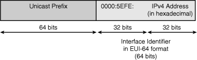
![]() The 64-bit IPv6 prefix can be any valid unicast prefix, including a global routable prefix, a link-local prefix, or even a 6to4 prefix. The prefix should be selected according to the address plan for the network.
The 64-bit IPv6 prefix can be any valid unicast prefix, including a global routable prefix, a link-local prefix, or even a 6to4 prefix. The prefix should be selected according to the address plan for the network.
![]() The upper 32 bits of the interface ID are 0000:5EFE, a reserved OUI value indicating an IPv6 ISATAP address. The lower (least significant) 32 bits of the interface ID contain the IPv4 address of the interface (written in hexadecimal). This embedded IPv4 address is used to create the tunnel, similar to other mechanisms. For example, consider the IPv4 address 172.16.101.1. From the earlier Figure 8-52, the hexadecimal equivalent of this address is AC10:6501. Therefore the 64-bit interface ID would be 0000:5EFE:AC10:6501.
The upper 32 bits of the interface ID are 0000:5EFE, a reserved OUI value indicating an IPv6 ISATAP address. The lower (least significant) 32 bits of the interface ID contain the IPv4 address of the interface (written in hexadecimal). This embedded IPv4 address is used to create the tunnel, similar to other mechanisms. For example, consider the IPv4 address 172.16.101.1. From the earlier Figure 8-52, the hexadecimal equivalent of this address is AC10:6501. Therefore the 64-bit interface ID would be 0000:5EFE:AC10:6501.
![]() As a transition strategy, ISATAP is an ideal, scalable solution for enterprise campus and branch sites because IPv6 connectivity can be automatically activated over an existing IPv4 network while the organization gradually migrates to an all-IPv6 network. Only the ISATAP router requires configuration. (Note that a best practice is to deploy more ISATAP routers for high availability.)
As a transition strategy, ISATAP is an ideal, scalable solution for enterprise campus and branch sites because IPv6 connectivity can be automatically activated over an existing IPv4 network while the organization gradually migrates to an all-IPv6 network. Only the ISATAP router requires configuration. (Note that a best practice is to deploy more ISATAP routers for high availability.)
![]() ISATAP is supported in popular operating systems including Windows XP, Vista, Windows 7, and Linux. An ISATAP tunnel is typically created from a host, such as a PC, to an ISATAP router. The tunnel is established using the IPv4 addresses of both the host and the router, across the IPv4 campus. The host establishes the tunnel only when it needs to. Hosts can discover the tunnel destination address (the IPv4 address of the router) dynamically through DNS or via a local statically configured definition (on the host itself). Because both IPv4 and tunneled IPv6 packets are transported over a single common IPv4 infrastructure, IPv4-dependent applications can continue to use IPv4 while newer IPv6-capable applications can be deployed immediately.
ISATAP is supported in popular operating systems including Windows XP, Vista, Windows 7, and Linux. An ISATAP tunnel is typically created from a host, such as a PC, to an ISATAP router. The tunnel is established using the IPv4 addresses of both the host and the router, across the IPv4 campus. The host establishes the tunnel only when it needs to. Hosts can discover the tunnel destination address (the IPv4 address of the router) dynamically through DNS or via a local statically configured definition (on the host itself). Because both IPv4 and tunneled IPv6 packets are transported over a single common IPv4 infrastructure, IPv4-dependent applications can continue to use IPv4 while newer IPv6-capable applications can be deployed immediately.
![]() The main limitation of ISATAP is that it does not support IPv6 multicast. This is not an issue for static routing or BGP (which uses TCP unicasts to establish the peering sessions). However, because dynamic IGPs such as RIPng and OSPFv3 use multicast, they are not inherently supported in ISATAP. There is a workaround for OSPFv3, though: A list of neighbors can be specified, and unicast hello packets rather than multicast packets are sent to the neighbors in the list.
The main limitation of ISATAP is that it does not support IPv6 multicast. This is not an issue for static routing or BGP (which uses TCP unicasts to establish the peering sessions). However, because dynamic IGPs such as RIPng and OSPFv3 use multicast, they are not inherently supported in ISATAP. There is a workaround for OSPFv3, though: A list of neighbors can be specified, and unicast hello packets rather than multicast packets are sent to the neighbors in the list.
![]() Another ISATAP issue is that it cannot operate across a NAT device. This might not be a significant issue because ISATAP is intended to be used inside an organization,
Another ISATAP issue is that it cannot operate across a NAT device. This might not be a significant issue because ISATAP is intended to be used inside an organization,
ISATAP Tunnel Configuration and Verification Commands
![]() The configuration and verification of ISATAP tunnels in this section use many of the commands explored earlier in this chapter. Other commands used in the upcoming examples are noted in this section.
The configuration and verification of ISATAP tunnels in this section use many of the commands explored earlier in this chapter. Other commands used in the upcoming examples are noted in this section.
![]() In this case, only one new command is used: The tunnel mode ipv6ip isatap interface configuration command specifies IPv6 automatic tunneling mode using an ISATAP address.
In this case, only one new command is used: The tunnel mode ipv6ip isatap interface configuration command specifies IPv6 automatic tunneling mode using an ISATAP address.
ISATAP Tunnel Configuration and Verification Example
![]() Figure 8-55 illustrates a network used to demonstrate the configuration and verification of an ISATAP tunnel. Instead of a host-to-router scenario, this is a router-to-router scenario, using the same network as in Figure 8-53, with the same IPv4 addresses on the loopback interfaces. Of course, the difference is that now an ISATAP tunnel will be created over the IPv4 network, so the tunnel IPv6 addresses will be created automatically. Recall that there are two IPv6 networks, 13::/64 and 24::/64, separated by an IPv4-only network, and IPv4 RIP is running between R1 and R2 to provide connectivity between the loopback interface networks. RIPng is running between R1 and R3, and between R2 and R4.
Figure 8-55 illustrates a network used to demonstrate the configuration and verification of an ISATAP tunnel. Instead of a host-to-router scenario, this is a router-to-router scenario, using the same network as in Figure 8-53, with the same IPv4 addresses on the loopback interfaces. Of course, the difference is that now an ISATAP tunnel will be created over the IPv4 network, so the tunnel IPv6 addresses will be created automatically. Recall that there are two IPv6 networks, 13::/64 and 24::/64, separated by an IPv4-only network, and IPv4 RIP is running between R1 and R2 to provide connectivity between the loopback interface networks. RIPng is running between R1 and R3, and between R2 and R4.

![]() Notice that the IPv6 tunnel addresses, on network 12:12::/64, are derived from the loopback IPv4 addresses. R1’s loopback address is 172.16.101.1. As discussed earlier, the hexadecimal equivalent of this address is AC10:6501, and therefore its 64-bit interface ID is 0000:5EFE:AC10:6501. Its IPv6 address is 12:12::0000:5EFE:AC10:6501, which can also be written as 12:12::5EFE:AC10:6501. Similarly, R2’s loopback address is 172.16.102.1. The hexadecimal equivalent of this address is AC10:6601, and therefore its 64-bit interface ID is 0000:5EFE:AC10:6601. Its IPv6 address is 12:12::0000:5EFE:AC10:6601, which can also be written as 12:12::5EFE:AC10:6601.
Notice that the IPv6 tunnel addresses, on network 12:12::/64, are derived from the loopback IPv4 addresses. R1’s loopback address is 172.16.101.1. As discussed earlier, the hexadecimal equivalent of this address is AC10:6501, and therefore its 64-bit interface ID is 0000:5EFE:AC10:6501. Its IPv6 address is 12:12::0000:5EFE:AC10:6501, which can also be written as 12:12::5EFE:AC10:6501. Similarly, R2’s loopback address is 172.16.102.1. The hexadecimal equivalent of this address is AC10:6601, and therefore its 64-bit interface ID is 0000:5EFE:AC10:6601. Its IPv6 address is 12:12::0000:5EFE:AC10:6601, which can also be written as 12:12::5EFE:AC10:6601.
![]() The objective of this example is to again provide full connectivity between the IPv6 islands over the IPv4-only infrastructure. The first step is to configure routers R1 and R2 so that they can establish the ISATAP tunnel between them. Example 8-121 illustrates the R1 and R2 configurations. Notice that the configuration is similar to the previous automatic tunnel configurations. Again, the tunnel destination is not specified, because the destination IPv4 address is embedded in the IPv6 address. This time an IPv6 address is assigned to the tunnel interface, but only the 64-bit prefix is specified. The eui-64 keyword is entered, so that the router selects the correct 64-bit interface ID. The tunnel mode ipv6ip isatap command is specified on each tunnel interface. It is at this point that the router calculates the IPv6 ISATAP address, using the specified 64-bit prefix, the ISATAP OUI, and the IPv4 address of the tunnel source (in hexadecimal format). As before, as soon as the tunnel has been created, the tunnel interface comes up.
The objective of this example is to again provide full connectivity between the IPv6 islands over the IPv4-only infrastructure. The first step is to configure routers R1 and R2 so that they can establish the ISATAP tunnel between them. Example 8-121 illustrates the R1 and R2 configurations. Notice that the configuration is similar to the previous automatic tunnel configurations. Again, the tunnel destination is not specified, because the destination IPv4 address is embedded in the IPv6 address. This time an IPv6 address is assigned to the tunnel interface, but only the 64-bit prefix is specified. The eui-64 keyword is entered, so that the router selects the correct 64-bit interface ID. The tunnel mode ipv6ip isatap command is specified on each tunnel interface. It is at this point that the router calculates the IPv6 ISATAP address, using the specified 64-bit prefix, the ISATAP OUI, and the IPv4 address of the tunnel source (in hexadecimal format). As before, as soon as the tunnel has been created, the tunnel interface comes up.
R1(config-if)#
%LINEPROTO-5-UPDOWN: Line protocol on Interface Tunnel12, changed state to down
R1(config-if)#no ip address
R1(config-if)#ipv6 address 12:12::/64 eui-64
R1(config-if)#tunnel source loopback 101
R1(config-if)#tunnel mode ipv6ip isatap
R1(config-if)#
%LINEPROTO-5-UPDOWN: Line protocol on Interface Tunnel12, changed state to up
R1(config-if)#
R2(config)#interface tunnel 12
R2(config-if)#
%LINEPROTO-5-UPDOWN: Line protocol on Interface Tunnel12, changed state to down
R2(config-if)#no ip address
R2(config-if)#ipv6 address 12:12::/64 eui-64
R2(config-if)#tunnel source loopback 102
R2(config-if)#tunnel mode ipv6ip isatap
R2(config-if)#
%LINEPROTO-5-UPDOWN: Line protocol on Interface Tunnel12, changed state to up
R2(config-if)#^Z
R2#
![]() To examine the tunnel interface status, the show interface tunnel command is used, as shown in Example 8-122. This output confirms that the encapsulation is set to tunnel, the tunnel source is the IPv4 address of the loopback interface, and the tunnel protocol/transport is IPv6 ISATAP. Notice that the tunnel destination is unknown; it is determined when the tunnel is used. The show ipv6 interface tunnel command is used next in the example, to view the IPv6 properties of the interface. This output confirms that the router concatenated the prefix 12:12::/64 with the ISATAP OUI 0000:5EFE and the IPv4 address AC10:6501, to create the IPv6 address of the tunnel 12:12::5EFE:AC10:6501. Notice that the link-local address of the tunnel interface has the same 64-bit interface ID; it of course has a different prefix, the FE80 link-local prefix. Therefore, for ISATAP tunnels, the global unicast address and the link-local address are created on the interface.
To examine the tunnel interface status, the show interface tunnel command is used, as shown in Example 8-122. This output confirms that the encapsulation is set to tunnel, the tunnel source is the IPv4 address of the loopback interface, and the tunnel protocol/transport is IPv6 ISATAP. Notice that the tunnel destination is unknown; it is determined when the tunnel is used. The show ipv6 interface tunnel command is used next in the example, to view the IPv6 properties of the interface. This output confirms that the router concatenated the prefix 12:12::/64 with the ISATAP OUI 0000:5EFE and the IPv4 address AC10:6501, to create the IPv6 address of the tunnel 12:12::5EFE:AC10:6501. Notice that the link-local address of the tunnel interface has the same 64-bit interface ID; it of course has a different prefix, the FE80 link-local prefix. Therefore, for ISATAP tunnels, the global unicast address and the link-local address are created on the interface.
Tunnel12 is up, line protocol is up
Hardware is Tunnel
MTU 1514 bytes,BW 9 Kbit/sec, DLY 500000 usec
reliability 255/255, txload 1/255, rxload 1/255
Encapsulation TUNNEL, loopback not set
Keepalive not set
Tunnel source 172.16.101.1 (Loopback101), destination UNKNOWN
Tunnel protocol/transport IPv6 ISATAP
Fast tunneling enabled
Tunnel transmit bandwidth 8000 (kbps)
Tunnel receive bandwidth 8000 (kbps)
Last input never, output 00:00:23, output hang never
Last clearing of "show interface" counters never
Input queue: 0/75/0/0 (size/max/drops/flushes); Total output
R1(config-if)#do show ipv6 interface tunnel 12
Tunnel12 is up, line protocol is up
IPv6 is enabled, link-local address is FE80::5EFE:AC10:6501
Global unicast address(es):
12::12::5EFE:AC10:6501, subnet is 12:12::/64 [EUI]
Joined group address(es):
FF02::1
FF02::2
FF02::1:FF10:6501
MTU is 1480 bytes
ICMP error messages limited to one every 100 milliseconds
ICMP redirects are enabled
ND DAD is not supported
ND reachable time is 30000 milliseconds
Hosts use stateless autoconfig for addresses.
R1(config-if)#
![]() To verify connectivity, debugging is enabled and R2’s tunnel IPv6 address is pinged from R1, as shown in Example 8-123. The ping is successful. The debug output confirms that the IPv4 addresses are being extracted from the ISATAP addresses to establish the tunnel across the network when IPv6 packets need to be sent. The ping is repeated, this time using R2’s tunnel IPv6 link-local address; recall that the interface must be specified when a link-local address is used. The ping is successful. Unlike the previous tunneling mechanisms we discussed, ISATAP tunnels have predictable link-local addresses that are automatically created and use the tunnel mechanism. ISATAP is designed for traffic within a site, so that for hosts the tunnel appears as a connection to a normal Ethernet interface.
To verify connectivity, debugging is enabled and R2’s tunnel IPv6 address is pinged from R1, as shown in Example 8-123. The ping is successful. The debug output confirms that the IPv4 addresses are being extracted from the ISATAP addresses to establish the tunnel across the network when IPv6 packets need to be sent. The ping is repeated, this time using R2’s tunnel IPv6 link-local address; recall that the interface must be specified when a link-local address is used. The ping is successful. Unlike the previous tunneling mechanisms we discussed, ISATAP tunnels have predictable link-local addresses that are automatically created and use the tunnel mechanism. ISATAP is designed for traffic within a site, so that for hosts the tunnel appears as a connection to a normal Ethernet interface.
Tunnel Interface debugging is on
R1#
R1#ping 12:12::5EFE:AC10:6601
Type escape sequence to abort.
Sending 5, 100-byte ICMP Echos to 12:12::5EFE:AC10:6601, timeout is 2 seconds:
!!!!!
Success rate is 100 percent (5/5), round-trip min/avg = 16/17/20 ms
Tunnel12 count tx, adding 20 encap bytes
Tunnel12: IPv6/IP to classify 172.16.102.1->172.16.101.1 (tbl=0, "default"
len=120 ttl=254
tos=0x0)
Tunnel12: IPv6/IP (PS) to decaps 172.16.102.1->172.16.101.1 (tbl=0, "default",
len=120,ttl=254)
Tunnel12: decapsulated IPv6/IP packet (len 120)
Tunnel12 count tx, adding 20 encap bytes
Tunnel12: IPv6/IP to classify 172.16.102.1->172.16.101.1 (tbl=0, "default"
len=120 ttl=254
tos=0x0)
Tunnel12: IPv6/IP (PS) to decaps 172.16.102.1->172.16.101.1 (tbl=0, "default",
len=120,ttl=254)
Tunnel12: decapsulated IPv6/IP packet (len 120)
![]() To reach destinations beyond the tunnel, a static route must be added. Example 8-124 illustrates the use of a static route on R1, using R2’s link-local address. Note that the outgoing interface must again be specified in the static route command when using a link-local address. This static route points to R2’s link-local address as the way to get to the 24::/64 network between R2 and R4. Because this IPv6 address has the IPv4 address embedded within it, the tunnel is created, and a ping from R1 to R4 works, as also shown in the example. The debug output verifies that the destination IPv4 address of the tunnel is selected (from the IPv6 address in the static route).
To reach destinations beyond the tunnel, a static route must be added. Example 8-124 illustrates the use of a static route on R1, using R2’s link-local address. Note that the outgoing interface must again be specified in the static route command when using a link-local address. This static route points to R2’s link-local address as the way to get to the 24::/64 network between R2 and R4. Because this IPv6 address has the IPv4 address embedded within it, the tunnel is created, and a ping from R1 to R4 works, as also shown in the example. The debug output verifies that the destination IPv4 address of the tunnel is selected (from the IPv6 address in the static route).
% Interface has to be specified for a link-local nexthop
R1(config)#ipv6 route 24::/64 tunnel12 FE80::5EFE:AC10:6601
R1(config)#do ping 24::4
Type escape sequence to abort.
Sending 5, 100-byte ICMP Echos to 24::4, timeout is 2 seconds:
!!!!!
Success rate is 100 percent (5/5), round-trip min/avg/max = 16/18/20 ms
R1(config)#
Tunnel12 count tx, adding 20 encap bytes
Tunnel12: IPv6/IP to classify 172.16.102.1->172.16.101.1 (tbl=0, "default"
len=120 ttl=254
tos=0x0)
Tunnel12: IPv6/IP (PS) to decaps 172.16.102.1->172.16.101.1 (tbl=0, "default",
len=120,ttl=254)
Tunnel12: decapsulated IPv6/IP packet (len 120)
Tunnel12 count tx, adding 20 encap bytes
Tunnel12: IPv6/IP to classify 172.16.102.1->172.16.101.1 (tbl=0, "default"
len=120 ttl=254
tos=0x0)
Tunnel12: IPv6/IP (PS) to decaps 172.16.102.1->172.16.101.1 (tbl=0, "default",
len=120,ttl=254)
Tunnel12: decapsulated IPv6/IP packet (len 120)
0 comments
Post a Comment