
Routing IPv6 Traffic
![]() This section describes the IPv6 routing protocols, and then explores each in detail. IPv6 policy routing and redistribution between the routing protocols is also examined.
This section describes the IPv6 routing protocols, and then explores each in detail. IPv6 policy routing and redistribution between the routing protocols is also examined.
 IPv6 Routing Protocols
![]() IPv6 uses the same “longest-prefix match” route preference method that IPv4 CIDR uses. Updates to the existing IPv4 routing protocols were necessary for handling the longer IPv6 addresses and different header structures. Currently, the following updated routing protocols are available for use with IPv6:
IPv6 uses the same “longest-prefix match” route preference method that IPv4 CIDR uses. Updates to the existing IPv4 routing protocols were necessary for handling the longer IPv6 addresses and different header structures. Currently, the following updated routing protocols are available for use with IPv6:
- Static routes
- RIP new generation (RIPng) (defined in RFC 2080, RIPng for IPv6)
- OSPFv3 (defined in RFC 5340, OSPF for IPv6)
- Intermediate System-Intermediate System (IS-IS) for IPv6
- Enhanced Interior Gateway Routing Protocol (EIGRP) for IPv6
- Multiprotocol Border Gateway Protocol Version 4 (MP-BGP4 or MBGP) (defined in RFC 2545, Use of BGP-4 Multiprotocol Extensions for IPv6 Inter-Domain Routing, and RFC 4760, Multiprotocol Extensions for BGP-4)
![]() Static routes, RIPng, OSPFv3, EIGRP for IPv6, and MBGP are described in the following sections.
Static routes, RIPng, OSPFv3, EIGRP for IPv6, and MBGP are described in the following sections.
| Note |
|
![]() Recall that the Cisco IOS ipv6 unicast-routing global configuration command for IPv6 enables IPv6 routing, and is required before any IPv6 routing protocol is configured.
Recall that the Cisco IOS ipv6 unicast-routing global configuration command for IPv6 enables IPv6 routing, and is required before any IPv6 routing protocol is configured.
Static Routing
![]() Static routes in IPv6 are used and configured similarly to static routes in IPv4. Static routes are useful in many situations, including for branch office to headquarters connectivity where the overhead of a routing protocol is not necessary.
Static routes in IPv6 are used and configured similarly to static routes in IPv4. Static routes are useful in many situations, including for branch office to headquarters connectivity where the overhead of a routing protocol is not necessary.
Static Route Configuration and Verification Commands
![]() IPv6 static routes can be configured with the ipv6 route ipv6-prefix/prefix-length {ipv6-address | interface-type interface-number [ipv6-address]} [administrative-distance] [administrative-multicast-distance | unicast | multicast] [next-hop-address] [tag tag] global configuration command. The parameters of this command are described in Table 8-2.
IPv6 static routes can be configured with the ipv6 route ipv6-prefix/prefix-length {ipv6-address | interface-type interface-number [ipv6-address]} [administrative-distance] [administrative-multicast-distance | unicast | multicast] [next-hop-address] [tag tag] global configuration command. The parameters of this command are described in Table 8-2.
|
| |
|---|---|
|
|
|
|
|
|
|
|
|
|
|
|
|
|
|
|
|
|
|
|
|
|
|
|
|
|
|
![]() Some of the many types of static routes that can be created with this command are as follows:
Some of the many types of static routes that can be created with this command are as follows:
- A directly attached static route is created using only the interface-type and interface-number parameters. The specified interface must be up and have IPv6 enabled. The destination prefix is assumed to be reachable out of the specified interface; the packet’s destination address is used as the next-hop address. An example is ipv6 route 2001:CC1E::/32 serial 0/0/0, which specifies that 2001:CC1E::/32 is reachable via the Serial 0/0/0 interface.
- A recursive static route is created using only the next-hop address parameter. An example is ipv6 route 2001:CC1E::/32 2001:12::1, which specifies that 2001:CC1E::/32 is reachable via the neighbor with address 2001:12::1. The router uses its routing table to determine the appropriate interface to use, which is the interface used to reach the next-hop address, so there must be such a route in the routing table. IPv6 recursive static routes are checked at 1-minute intervals. Therefore a recursive static route may take up to one minute to be inserted into the routing table once its next hop becomes valid. Likewise, it may take a minute or so for the route to disappear from the table if the next hop becomes invalid.
- A fully specified static route includes both the outgoing interface and the next hop address. An example is ipv6 route 2001:CC1E::/32 serial 0/0/0 2001:12::1, which specifies that 2001:CC1E::/32 is reachable via the neighbor with address 2001:12::1 on the Serial 0/0/0 interface. Fully specified static routes are used on multiaccess interfaces, on which there could be multiple devices so specifying only the interface is not sufficient.
- A floating static route can also be configured, which again operates similar to its IPv4 counterpart. The administrative distance of the static route is set to a value higher than the administrative distance of any dynamic routing protocol or other method used to reach a particular destination. The static routes function as a backup to the routes discovered by the dynamic routing protocol and will not be installed in the routing table unless the entry for the dynamic routing protocol is deleted, for example because of a link failure.
![]() The show ipv6 route [ipv6-address | ipv6-prefix/prefix-length | protocol | interface-type interface-number] EXEC command displays the current contents of the IPv6 routing table. The parameters of this command are described in Table 8-3.
The show ipv6 route [ipv6-address | ipv6-prefix/prefix-length | protocol | interface-type interface-number] EXEC command displays the current contents of the IPv6 routing table. The parameters of this command are described in Table 8-3.
|
|
|
|---|---|
|
|
|
|
|
|
|
|
|
|
|
|
Static Route Configuration and Verification Example
![]() Figure 8-24 shows a network used for a static route example. The R1 router could, for example, be at the headquarters of an organization, and the R2 router at a branch office.
Figure 8-24 shows a network used for a static route example. The R1 router could, for example, be at the headquarters of an organization, and the R2 router at a branch office.
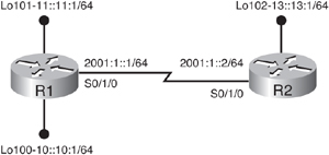
![]() Example 8-34 shows the configuration and verification of the R1 and R2 routers. Notice that the ipv6 unicast-routing command is required even with static routes. R1 has a static route to the R2 loopback via its Serial 0/1/0 interface. R2 has a default static route, using the ::/0 prefix/length combination. The show ipv6 route static command verifies that the static route is in the routing table.
Example 8-34 shows the configuration and verification of the R1 and R2 routers. Notice that the ipv6 unicast-routing command is required even with static routes. R1 has a static route to the R2 loopback via its Serial 0/1/0 interface. R2 has a default static route, using the ::/0 prefix/length combination. The show ipv6 route static command verifies that the static route is in the routing table.
R1(config)#ipv6 unicast-routing
R1(config)#ipv6 route 13::/64 s0/1/0
R1(config)#do show ipv6 route static
IPv6 Routing Table – 9 entries
Codes: C – Connected, L – Local, S – Static, R – RIP, B – BGP
      U – Per-user Static route
      I1 – ISIS L1, I2 – ISIS L2, IA – ISIS interarea, IS – ISIS summary
      O – OSPF intra, OI – OSPF inter, OE1 – OSPF ext 1, OE2 – OSPF ext 2
      ON1 – OSPF NSSA ext 1, ON2 – OSPF NSSA ext 2
S    13::/64 [1/0]
     via ::, Serial0/1/0
R1(config)#


R2(config)#ipv6 unicast-routing
R2(config)#ipv6 route ::/0 s0/1/0
R2(config)#do show ipv6 route static
IPv6 Routing Table – 7 entries
Codes: C – Connected, L – Local, S – Static, R – RIP, B – BGP
      U – Per-user Static route
      I1 – ISIS L1, I2 – ISIS L2, IA – ISIS interarea, IS – ISIS summary
      O – OSPF intra, OI – OSPF inter, OE1 – OSPF ext 1, OE2 – OSPF ext 2
      ON1 – OSPF NSSA ext 1, ON2 – OSPF NSSA ext 2
S    ::/0 [1/0]
     via ::, Serial0/1/0
R2(config)#
![]() Example 8-35 illustrates that the static routes are working. We can ping from R1 to R2’s loopback address, and ping from R2 to both of R1’s loopback addresses.
Example 8-35 illustrates that the static routes are working. We can ping from R1 to R2’s loopback address, and ping from R2 to both of R1’s loopback addresses.
R1#ping 13::13:1
Type escape sequence to abort.
Sending 5, 100-byte ICMP Echos to 13::13:1, timeout is 2 seconds:
!!!!!
Success rate is 100 percent (5/5), round-trip min/avg/max = 12/13/16 ms
R1#


R2#ping 11::11:1
Type escape sequence to abort.
Sending 5, 100-byte ICMP Echos to 11::11:1, timeout is 2 seconds:
!!!!!
Success rate is 100 percent (5/5), round-trip min/avg/max = 12/15/16 ms
R2#
R2#ping 10::10:1
Type escape sequence to abort.
Sending 5, 100-byte ICMP Echos to 10::10:1, timeout is 2 seconds:
!!!!!
Success rate is 100 percent (5/5), round-trip min/avg/max = 12/12/16 ms
R2#
RIPng
![]() Similar to IPv4’s RIP, RIPng is a distance vector routing protocol with a metric limit of 15 hops that uses split horizon and poison reverse to prevent routing loops. IPv6 features include the following:
Similar to IPv4’s RIP, RIPng is a distance vector routing protocol with a metric limit of 15 hops that uses split horizon and poison reverse to prevent routing loops. IPv6 features include the following:
- RIPng is based on IPv4 RIP Version 2 (RIPv2).
- RIPng uses IPv6 for transport.
- RIPng uses link-local addresses as source addresses.
- RIPng uses an IPv6 prefix and a next-hop IPv6 address.
- RIPng uses the multicast address FF02::9, the all RIPng routers multicast address, as the destination address for RIPng updates.
- The RIPng administrative distance is 120.
RIPng Configuration and Verification Commands
![]() The ipv6 rip name enable interface configuration command enables a RIPng process on an interface. The name parameter is the name of the RIPng routing process; it is automatically created if it does not already exist.
The ipv6 rip name enable interface configuration command enables a RIPng process on an interface. The name parameter is the name of the RIPng routing process; it is automatically created if it does not already exist.
![]() The ipv6 router rip name global configuration command configures the RIPng routing process and enters router configuration mode. The name parameter is the name of the RIPng routing process.
The ipv6 router rip name global configuration command configures the RIPng routing process and enters router configuration mode. The name parameter is the name of the RIPng routing process.
![]() The no split-horizon router configuration command disables the split horizon processing of RIPng updates.
The no split-horizon router configuration command disables the split horizon processing of RIPng updates.
![]() The show ipv6 protocols [summary] EXEC command display the parameters and current state of the active IPv6 routing protocol processes. The summary keyword specifies that only the configured routing protocol process names are displayed.
The show ipv6 protocols [summary] EXEC command display the parameters and current state of the active IPv6 routing protocol processes. The summary keyword specifies that only the configured routing protocol process names are displayed.
![]() The debug ipv6 rip [interface-type interface-number] EXEC command displays RIPng routing transaction debug messages. The interface-type interface-number specifies the interface about which to display debug messages.
The debug ipv6 rip [interface-type interface-number] EXEC command displays RIPng routing transaction debug messages. The interface-type interface-number specifies the interface about which to display debug messages.
RIPng Configuration and Verification Example
![]() Figure 8-25 illustrates a network used for a RIPng example. The routers are connected via a Frame Relay network. The R1 router could, for example, be at the headquarters of an organization, and the R2 and R3 routers at branch offices.
Figure 8-25 illustrates a network used for a RIPng example. The routers are connected via a Frame Relay network. The R1 router could, for example, be at the headquarters of an organization, and the R2 and R3 routers at branch offices.
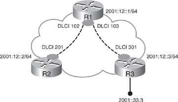
![]() Example 8-36 illustrates, for the R1, R2, and R3 routers, the current configuration of the Frame Relay interfaces, and the addition of mapping statements for the global unicast addresses. Each router already had an IPv6 address configured on its Frame Relay interface. On Router R1, maps to both R2 and R3 are added. On Router R2 and R3, only a map to R1 is added.
Example 8-36 illustrates, for the R1, R2, and R3 routers, the current configuration of the Frame Relay interfaces, and the addition of mapping statements for the global unicast addresses. Each router already had an IPv6 address configured on its Frame Relay interface. On Router R1, maps to both R2 and R3 are added. On Router R2 and R3, only a map to R1 is added.
R1#show run interface s0/0/0
Building configuration...
Current configuration : 132 bytes
!
interface Serial0/0/0
 no ip address
 encapsulation frame-relay IETF
 ipv6 address 2001:12::1/64
 frame-relay lmi-type cisco
end
R1#
R1#config t
R1(config)#interface s0/0/0
R1(config-if)#frame-relay map ipv6 2001:12::2 102
R1(config-if)#frame-relay map ipv6 2001:12::3 103
R1(config-if)#


R2(config)#do show run interface s1/1.7
Building configuration...
Current configuration : 80 bytes
!
interface Serial1/1.7 multipoint
 ipv6 address 2001:12::2/64
 cdp enable
end
R2(config)#interface s1/1.7
R2(config-subif)#frame-relay map ipv6 2001:12::1 201
R2(config-subif)#


R3(config)#do show run interface s1/1.7
Building configuration...
Current configuration : 80 bytes
!
interface Serial1/1.7 multipoint
 ipv6 address 2001:12::3/64
 cdp enable
end
R3(config)#interface s1/1.7
R3(config-subif)#frame-relay map ipv6 2001:12::1 301
R3(config-subif)#
![]() Example 8-37 shows the results of the connectivity verification between the sites. R1 can ping both R2 and R3; R2 and R3 can ping R1.
Example 8-37 shows the results of the connectivity verification between the sites. R1 can ping both R2 and R3; R2 and R3 can ping R1.
R1#ping 2001:12::2
Type escape sequence to abort.
Sending 5, 100-byte ICMP Echos to 2001:12::2, timeout is 2 seconds:
!!!!!
Success rate is 100 percent (5/5), round-trip min/avg/max = 56/57/60 ms
R1#ping 2001:12::3
Type escape sequence to abort.
Sending 5, 100-byte ICMP Echos to 2001:12::3, timeout is 2 seconds:
!!!!!
Success rate is 100 percent (5/5), round-trip min/avg/max = 56/57/60 ms
R1#


R2#ping 2001:12::1
Type escape sequence to abort.
Sending 5, 100-byte ICMP Echos to 2001:12::1, timeout is 2 seconds:
!!!!!
Success rate is 100 percent (5/5), round-trip min/avg/max = 56/57/61 ms
R2#


R3#ping 2001:12::1
Type escape sequence to abort.
Sending 5, 100-byte ICMP Echos to 2001:12::1, timeout is 2 seconds:
!!!!!
Success rate is 100 percent (5/5), round-trip min/avg/max = 56/57/60 ms
R3#
![]() However, there is no connectivity between the LANs behind the routers. In this network, RIPng will be used to provide connectivity. Like all the IPv6 routing protocols, RIPng uses link-local addresses. Recall that on a Frame Relay network we must configure maps for the link-local addresses, not only for the global unicast addresses. The link-local addresses for each interface can be obtained using the show ipv6 interface command on destination routers; simply copy and paste the addresses into the sending router configuration. Example 8-38 illustrates the configuration of the maps to the link-local addresses, on all three routers.
However, there is no connectivity between the LANs behind the routers. In this network, RIPng will be used to provide connectivity. Like all the IPv6 routing protocols, RIPng uses link-local addresses. Recall that on a Frame Relay network we must configure maps for the link-local addresses, not only for the global unicast addresses. The link-local addresses for each interface can be obtained using the show ipv6 interface command on destination routers; simply copy and paste the addresses into the sending router configuration. Example 8-38 illustrates the configuration of the maps to the link-local addresses, on all three routers.
R1(config)#interface s0/0/0
R1(config-if)#frame-relay map ipv6 FE80::250:73FF:FE3D:6A20 103
R1(config-if)#frame-relay map ipv6 FE80::2B0:64FF:FE33:FB60 102
R1(config-if)#


R2(config)# interface s1/1.7
R2(config-subif)#frame-relay map ipv6 FE80::219:56FF:FE2C:9F60 201
R2(config-subif)#

R3(config)# interface s1/1.7
R3(config-subif)#frame-relay map ipv6 FE80::219:56FF:FE2C:9F60 301
R3(config-subif)#
![]() The next step is to enable RIPng, as shown in Example 8-39. The ipv6 unicast-routing command is configured first. A RIPng process called RIPTag is next created on the serial interface of each router; notice that this command is entered on an interface. However, it causes the global RIPTag process to be created automatically. (In other words, the process does not have to be created separately in global configuration mode.) The output of the show ipv6 protocols command confirms that the RIPng process RIPTag is configured.
The next step is to enable RIPng, as shown in Example 8-39. The ipv6 unicast-routing command is configured first. A RIPng process called RIPTag is next created on the serial interface of each router; notice that this command is entered on an interface. However, it causes the global RIPTag process to be created automatically. (In other words, the process does not have to be created separately in global configuration mode.) The output of the show ipv6 protocols command confirms that the RIPng process RIPTag is configured.
R1(config)#ipv6 unicast-routing
R1(config)#interface s0/0/0
R1(config-if)#ipv6 rip RIPTag ?
    default-information  Configure handling of default route
    enable                     Enable/disable RIP routing
    metric-offset            Adjust default metric increment
    summary-address   Configure address summarization
R1(config-if)#ipv6 rip RIPTag enable
R1(config-if)#do show ipv6 protocols
IPv6 Routing Protocol is "connected"
IPv6 Routing Protocol is "static"
IPv6 Routing Protocol is "rip RIPTag"
 Interfaces:
   Serial0/0/0
 Redistribution:
   None
R1(config-if)#


R2(config)#ipv6 unicast-routing
R2(config)#interface s1/1.7
R2(config-subif)#ipv6 rip RIPTag enable
R2(config-subif)#


R3(config)#ipv6 unicast-routing
R3(config)# interface s1/1.7
R3(config-subif)#ipv6 rip RIPTag enable
R3(config-subif)#do show ipv6 protocols
IPv6 Routing Protocol is "connected"
IPv6 Routing Protocol is "static"
IPv6 Routing Protocol is "rip RIPTag"
 Interfaces:
   Serial1/1.7
 Redistribution:
   None
R3(config-subif)#
![]() To confirm whether RIPng is working correctly, examine the debug ipv6 rip output on R1 shown in Example 8-40. Notice R1 is only sending RIPng messages; it is not receiving any messages from other routers.
To confirm whether RIPng is working correctly, examine the debug ipv6 rip output on R1 shown in Example 8-40. Notice R1 is only sending RIPng messages; it is not receiving any messages from other routers.
R1#debug ipv6 rip
RIP Routing Protocol debugging is on
R1#
*Aug 14 04:19:12.908: RIPng: Sending multicast update on Serial0/0/0 for RIPTag
*Aug 14 04:19:12.908:        src=FE80::219:56FF:FE2C:9F60
*Aug 14 04:19:12.908:        dst=FF02::9 (Serial0/0/0)
*Aug 14 04:19:12.908:        sport=521, dport=521, length=32
*Aug 14 04:19:12.908:        command=2, version=1, mbz=0, #rte=1
*Aug 14 04:19:12.908:        tag=0, metric=1, prefix=2001:12::/64
*Aug 14 04:19:40.524: RIPng: Sending multicast update on Serial0/0/0 for RIPTag
*Aug 14 04:19:40.524:        src=FE80::219:56FF:FE2C:9F60
*Aug 14 04:19:40.524:        dst=FF02::9 (Serial0/0/0)
*Aug 14 04:19:40.524:        sport=521, dport=521, length=32
*Aug 14 04:19:40.524:        command=2, version=1, mbz=0, #rte=1
*Aug 14 04:19:40.524:        tag=0, metric=1, prefix=2001:12::/64
![]() To understand why RIPng is not working, recall that RIPng uses multicast packets; notice the destination address FF02::9 in Example 8-40. When configuring the Frame Relay maps, the broadcast keyword was not specified; this is the keyword that allows both broadcast and multicast packets to go across the Frame Relay network. Without this keyword, multicast and broadcast packets do not go out. Therefore, the RIPng packets are not going across the PVCs, even though the debug output says they are going out the interface. Example 8-41 illustrates the output of the show frame-relay map command on R1; observe that there is no broadcast indicated. Example 8-41 also shows the corrected configuration of the Frame Relay maps on the three routers.
To understand why RIPng is not working, recall that RIPng uses multicast packets; notice the destination address FF02::9 in Example 8-40. When configuring the Frame Relay maps, the broadcast keyword was not specified; this is the keyword that allows both broadcast and multicast packets to go across the Frame Relay network. Without this keyword, multicast and broadcast packets do not go out. Therefore, the RIPng packets are not going across the PVCs, even though the debug output says they are going out the interface. Example 8-41 illustrates the output of the show frame-relay map command on R1; observe that there is no broadcast indicated. Example 8-41 also shows the corrected configuration of the Frame Relay maps on the three routers.
R1#show frame-relay map
Serial0/0/0 (up): ipv6 FE80::250:73FF:FE3D:6A20 dlci 103(0x67, 0x1870), static,
                      IETF, status defined, active
Serial0/0/0 (up): ipv6 FE80::2B0:64FF:FE33:FB60 dlci 102(0x66, 0x1860), static,
                      IETF, status defined, active
Serial0/0/0 (up): ipv6 2001:12::2 dlci 102(0x66, 0x1860), static,
                      IETF, status defined, active
Serial0/0/0 (up): ipv6 2001:12::3 dlci 103(0x67, 0x1870), static,
                      IETF, status defined, active
R1#config t
R1(config)#interface s0/0/0
R1(config-if)#frame-relay map ipv6 FE80::250:73FF:FE3D:6A20 103 broadcast
R1(config-if)#frame-relay map ipv6 FE80::2B0:64FF:FE33:FB60 102 broadcast
R1(config-if)#


R2(config-subif)#frame-relay map ipv6 FE80::219:56FF:FE2C:9F60 201 broadcast


R3(config-subif)#frame-relay map ipv6 FE80::219:56FF:FE2C:9F60 301 broadcast
![]() Note that the broadcast keyword is only required on the Frame Relay maps for the link-local addresses for RIPng (and other routing protocols) to function correctly, because these protocols use the link-local addresses to communicate between routers. This keyword is not required on the Frame Relay maps for the global unicast addresses, because they are not used by the routing protocols. (The keyword may be required for other traffic, but not for the routing protocols.)
Note that the broadcast keyword is only required on the Frame Relay maps for the link-local addresses for RIPng (and other routing protocols) to function correctly, because these protocols use the link-local addresses to communicate between routers. This keyword is not required on the Frame Relay maps for the global unicast addresses, because they are not used by the routing protocols. (The keyword may be required for other traffic, but not for the routing protocols.)
![]() Example 8-42 displays the output of the debug ipv6 rip command again on R1; RIPng updates are now being sent and received.
Example 8-42 displays the output of the debug ipv6 rip command again on R1; RIPng updates are now being sent and received.
R1#
RIP Routing Protocol debugging is on
*Aug 14 04:21:48.508: RIPng: response received from FE80::2B0:64FF:FE33:FB60 on
Serial0/0/0 for RIPTag
*Aug 14 04:21:48.508: src=FE80::2B0:64FF:FE33:FB60 (Serial0/0/0)
*Aug 14 04:21:48.508: dst=FF02::9
*Aug 14 04:21:48.508: sport=521, dport=521, length=32
*Aug 14 04:21:48.508: command=2, version=1, mbz=0, #rte=1
*Aug 14 04:21:48.512: tag=0, metric=1, prefix=2001:12::/64
*Aug 14 04:21:59.276: RIPng: Sending multicast update on Serial0/0/0 for RIPTag
*Aug 14 04:21:59.276: src=FE80::219:56FF:FE2C:9F60
*Aug 14 04:21:59.276: dst=FF02::9 (Serial0/0/0)
*Aug 14 04:21:59.276: sport=521, dport=521, length=32
*Aug 14 04:21:59.276: command=2, version=1, mbz=0, #rte=1
*Aug 14 04:21:59.276: tag=0, metric=1, prefix=2001:12::/64
![]() The R3 loopback interface also must be configured to participate in the RIPTag process, for it to be advertised by R3. Example 8-43 shows this configuration. Also shown is the show ipv6 route rip output on R1, in which the R3 loopback interface address is visible. A ping from R1 to this loopback address is successful. However, R2’s routing table does not contain the route to this address.
The R3 loopback interface also must be configured to participate in the RIPTag process, for it to be advertised by R3. Example 8-43 shows this configuration. Also shown is the show ipv6 route rip output on R1, in which the R3 loopback interface address is visible. A ping from R1 to this loopback address is successful. However, R2’s routing table does not contain the route to this address.
R3(config-if)#ipv6 rip RIPTag enable
R3(config-if)#
R1#show ipv6 route rip
IPv6 Routing Table – 9 entries
Codes: C – Connected, L – Local, S – Static, R – RIP, B – BGP
U – Per-user Static route
I1 – ISIS L1, I2 – ISIS L2, IA – ISIS interarea, IS – ISIS summary
O – OSPF intra, OI – OSPF inter, OE1 – OSPF ext 1, OE2 – OSPF ext 2
ON1 – OSPF NSSA ext 1, ON2 – OSPF NSSA ext 2
R 2001:33::/64 [120/2]
via FE80::250:73FF:FE3D:6A20, Serial0/0/0
R1#ping 2001:33::3
Type escape sequence to abort.
Sending 5, 100-byte ICMP Echos to 2001:33::3, timeout is 2 seconds:
!!!!!
Success rate is 100 percent (5/5), round-trip min/avg/max = 56/60/68 ms
R1#
R2#show ipv6 route rip
IPv6 Routing Table – 4 entries
Codes: C – Connected, L – Local, S – Static, R – RIP, B – BGP
U – Per-user Static route
I1 – ISIS L1, I2 – ISIS L2, IA – ISIS interarea, IS – ISIS summary
O – OSPF intra, OI – OSPF inter, OE1 – OSPF ext 1, OE2 – OSPF ext 2
ON1 – OSPF NSSA ext 1, ON2 – OSPF NSSA ext 2
R2#
![]() R2 is not learning about the R3 loopback address because of the split-horizon feature of RIPng. As a distance vector protocol, RIPng uses split horizon to help prevent routing loops. The split-horizon rule states that a router will not send out a route learned on an interface (such as the route to R3’s loopback that R1 learned on its Serial 0/0/0 interface) out of the same interface (such as to R2). Using subinterfaces is the best way to fix this problem. Alternatively, split horizon can be turned off. Here, we use the latter fix (but understand that routing loops could potentially be introduced). The no split-horizon command is configured on R1, which fixes the problem, as verified in Example 8-44.
R2 is not learning about the R3 loopback address because of the split-horizon feature of RIPng. As a distance vector protocol, RIPng uses split horizon to help prevent routing loops. The split-horizon rule states that a router will not send out a route learned on an interface (such as the route to R3’s loopback that R1 learned on its Serial 0/0/0 interface) out of the same interface (such as to R2). Using subinterfaces is the best way to fix this problem. Alternatively, split horizon can be turned off. Here, we use the latter fix (but understand that routing loops could potentially be introduced). The no split-horizon command is configured on R1, which fixes the problem, as verified in Example 8-44.
R1(config-rtr)#no split-horizon
R1(config-rtr)#
R2#show ipv6 route rip
IPv6 Routing Table - 5 entries
Codes: C – Connected, L – Local, S – Static, R – RIP, B – BGP
U – Per-user Static route
I1 – ISIS L1, I2 – ISIS L2, IA – ISIS interarea, IS – ISIS summary
O – OSPF intra, OI – OSPF inter, OE1 – OSPF ext 1, OE2 – OSPF ext 2
ON1 – OSPF NSSA ext 1, ON2 – OSPF NSSA ext 2
R 2001:33::/64 [120/3]
via FE80::219:56FF:FE2C:9F60, Serial1/1.7
R2#ping 2001:33::3
Type escape sequence to abort.
Sending 5, 100-byte ICMP Echos to 2001:33::3, timeout is 2 seconds:
!!!!!
Success rate is 100 percent (5/5) round-trip min/avg/max = 140/141/144ms
R2#
OSPFv3
![]() OSPFv3 is a new protocol implementation for IPv6. It uses the same mechanisms as OSPFv2, but is a major rewrite of the internals of the protocol.
OSPFv3 is a new protocol implementation for IPv6. It uses the same mechanisms as OSPFv2, but is a major rewrite of the internals of the protocol.
![]() OSPFv3 distributes (transports) IPv6 prefixes and runs directly over IPv6.
OSPFv3 distributes (transports) IPv6 prefixes and runs directly over IPv6.
![]() If both OSPFv2 and OSPFv3 are configured on a router, they run completely separate from each other and run a separate shortest path first (SPF) instance. In other words, the two protocols are like “ships in the night,” passing without knowing of the other’s existence.
If both OSPFv2 and OSPFv3 are configured on a router, they run completely separate from each other and run a separate shortest path first (SPF) instance. In other words, the two protocols are like “ships in the night,” passing without knowing of the other’s existence.
![]() OSPFv3 includes the following IPv6-specific features:
OSPFv3 includes the following IPv6-specific features:
- Every OSPFv2 IPv4-specific semantic is removed.
- Uses 128-bit IPv6 addresses.
- Uses link-local addresses as source addresses.
- Multiple addresses and OSPF instances per interface are permitted.
- Supports authentication (using IPsec).
- Runs over a link rather than a subnet.
![]() Recall that OSPF is link-state routing protocol. A link is an interface on a networking device, and a link-state protocol makes its routing decisions based on the states of the links that connect source and destination devices. The state of a link is a description of the interface and its relationship to its neighboring networking devices.
Recall that OSPF is link-state routing protocol. A link is an interface on a networking device, and a link-state protocol makes its routing decisions based on the states of the links that connect source and destination devices. The state of a link is a description of the interface and its relationship to its neighboring networking devices.
![]() For OSPFv3, the interface information includes the IPv6 prefix of the interface, the network mask, the type of network it is connected to, the routers connected to the network, and so forth. This information is propagated in various types of link-state advertisements (LSAs). A router’s collection of LSA data is stored in a link-state database (LSDB). The contents of the database, when subjected to Dijkstra’s algorithm, result in the creation of the OSPF routing table.
For OSPFv3, the interface information includes the IPv6 prefix of the interface, the network mask, the type of network it is connected to, the routers connected to the network, and so forth. This information is propagated in various types of link-state advertisements (LSAs). A router’s collection of LSA data is stored in a link-state database (LSDB). The contents of the database, when subjected to Dijkstra’s algorithm, result in the creation of the OSPF routing table.
Similarities Between OSPFv2 and OSPFv3
![]() Although most of the algorithms of OSPFv2 are the same as those of OSPFv3, some changes have been made in OSPFv3, particularly to handle the increased address size in IPv6 and the fact that OSPFv3 runs directly over IPv6. The similarities between OSPFv3 and OSPFv2 include the following:
Although most of the algorithms of OSPFv2 are the same as those of OSPFv3, some changes have been made in OSPFv3, particularly to handle the increased address size in IPv6 and the fact that OSPFv3 runs directly over IPv6. The similarities between OSPFv3 and OSPFv2 include the following:
- OSPFv3 uses the same basic packet types as OSPFv2, as shown in Table 8-4—hello, database description (DBD) (also called database description packets [DDP]), link-state request (LSR), link-state update (LSU), and link-state acknowledgment (LSAck). Some of the fields within the packets have changed. Table 8-4: OSPFv3 Packet Types
 Open table as spreadsheetPacket TypeName1Hello2DBD3LSR4LSU5LSAck
 - The mechanisms for neighbor discovery and adjacency formation are identical.
- OSPFv3 operation over NBMA topologies is the same as OSPFv2. The RFC-compliant nonbroadcast and point-to-multipoint modes are supported, and OSPFv3 also supports the Cisco modes such as point-to-point and broadcast.
- LSA flooding and aging are the same.
![]() All the optional capabilities of OSPFv2, including on-demand circuit support, stub areas and not-so-stubby areas (NSSAs), and the extensions to Multicast OSPF (MOSPF), are also supported in OSPFv3. All areas must be connected to area 0, unless virtual links are configured, the same as in OSPFv2.
All the optional capabilities of OSPFv2, including on-demand circuit support, stub areas and not-so-stubby areas (NSSAs), and the extensions to Multicast OSPF (MOSPF), are also supported in OSPFv3. All areas must be connected to area 0, unless virtual links are configured, the same as in OSPFv2.
Differences Between OSPFv2 and OSPFv3
![]() Because OSPFv2 is heavily dependent on the IPv4 address for its operation, changes were necessary in the OSPFv3 protocol to support IPv6, as outlined in RFC 5340. Some of the notable changes include platform-independent implementation, protocol processing per-link rather than per-node, explicit support for multiple instances per link, and changes in authentication and packet format.
Because OSPFv2 is heavily dependent on the IPv4 address for its operation, changes were necessary in the OSPFv3 protocol to support IPv6, as outlined in RFC 5340. Some of the notable changes include platform-independent implementation, protocol processing per-link rather than per-node, explicit support for multiple instances per link, and changes in authentication and packet format.
![]() Like RIPng, OSPFv3 uses IPv6 for transport and uses link-local addresses as source address.
Like RIPng, OSPFv3 uses IPv6 for transport and uses link-local addresses as source address.
![]() All OSPFv3 packets have a 16-byte header, in comparison to OSPFv2’s 24-byte header. The two headers are illustrated in Figure 8-26.
All OSPFv3 packets have a 16-byte header, in comparison to OSPFv2’s 24-byte header. The two headers are illustrated in Figure 8-26.


![]() OSPFv2 does not define or allow for multiple instances per link, although similar functionality can be implemented by using other mechanisms such as subinterfaces. In contrast, OSPFv3 has explicit support for multiple instances per link through the instance ID field in the packet header. This feature allows separate routing domains, each running OSPF, to use a common link. A single link could belong to multiple areas. Two instances need to have the same instance ID to communicate with each other. By default, the instance ID is 0, and it is increased for any additional instances.
OSPFv2 does not define or allow for multiple instances per link, although similar functionality can be implemented by using other mechanisms such as subinterfaces. In contrast, OSPFv3 has explicit support for multiple instances per link through the instance ID field in the packet header. This feature allows separate routing domains, each running OSPF, to use a common link. A single link could belong to multiple areas. Two instances need to have the same instance ID to communicate with each other. By default, the instance ID is 0, and it is increased for any additional instances.
![]() Authentication is no longer part of OSPFv3; it is now the job of IPv6 to make sure the right level of authentication is in use.
Authentication is no longer part of OSPFv3; it is now the job of IPv6 to make sure the right level of authentication is in use.
![]() OSPFv3 uses IPv6 link-local addresses to identify the OSPFv3 adjacency neighbors.
OSPFv3 uses IPv6 link-local addresses to identify the OSPFv3 adjacency neighbors.
![]() OSPFv2 is primarily concerned with the subnet (or prefix) on which it is operating, whereas OSPFv3 is concerned with the links to which the router is connected. As discussed, IPv6 uses the term link to indicate a communication facility or medium over which nodes can communicate at the link layer; OSPF interfaces connect to links instead of to IP subnets. Multiple IPv6 subnets can be assigned to a single link, and two nodes can talk directly over a single link, even if they do not share a common IPv6 subnet (IPv6 prefix), because they use the link-local addresses, rather than the global unicast addresses, to communicate. OSPFv3 therefore runs per-link instead of the IPv4 behavior of per-IP-subnet, and the terms network and subnet are generally replaced by the term link. This change affects the receiving of OSPFv3 protocol packets, and the contents of hello packets and network LSAs.
OSPFv2 is primarily concerned with the subnet (or prefix) on which it is operating, whereas OSPFv3 is concerned with the links to which the router is connected. As discussed, IPv6 uses the term link to indicate a communication facility or medium over which nodes can communicate at the link layer; OSPF interfaces connect to links instead of to IP subnets. Multiple IPv6 subnets can be assigned to a single link, and two nodes can talk directly over a single link, even if they do not share a common IPv6 subnet (IPv6 prefix), because they use the link-local addresses, rather than the global unicast addresses, to communicate. OSPFv3 therefore runs per-link instead of the IPv4 behavior of per-IP-subnet, and the terms network and subnet are generally replaced by the term link. This change affects the receiving of OSPFv3 protocol packets, and the contents of hello packets and network LSAs.
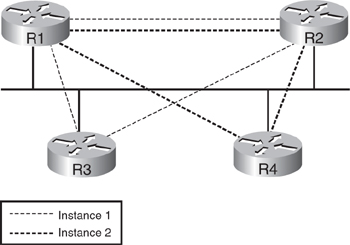
![]() Figure 8-27 illustrates an example of two instances of OSPFv3 running on the same physical network segment, using two different IPv6 prefixes.
Figure 8-27 illustrates an example of two instances of OSPFv3 running on the same physical network segment, using two different IPv6 prefixes.
![]() The multicast addresses used by OSPFv3 are as follows:
The multicast addresses used by OSPFv3 are as follows:
- FF02::5— This address represents all OSPFv3 routers on the link-local scope. It is equivalent to 224.0.0.5 in OSPFv2.
- FF02::6— This address represents all designated routers (DRs) on the link-local scope. It is equivalent to 224.0.0.6 in OSPFv2.
![]() Address semantics that were in OSPFv2 have been removed in OSPFv3, as follows:
Address semantics that were in OSPFv2 have been removed in OSPFv3, as follows:
- IPv6 addresses are not present in the OSPFv3 packet header (rather they are part of payload information).
- OSPFv3 router LSAs and network LSAs do not carry IPv6 addresses.
- The router ID, area ID, and link-state ID remain at 32 bits and are written in an IPv4-address format (dotted decimal).
- The DR and backup designated router (BDR) are now identified by their router ID, not by their IP address.
![]() For security, OSPFv3 uses IPv6 AH and ESP extension headers rather than the variety of authentication and confidentiality security mechanisms defined in OSPFv2.
For security, OSPFv3 uses IPv6 AH and ESP extension headers rather than the variety of authentication and confidentiality security mechanisms defined in OSPFv2.
OSPFv3 Configuration and Verification Commands
![]() Many of the OSPFv3 commands are similar to their OSPFv2 counterparts, with the ip keyword replaced by the ipv6 keyword.
Many of the OSPFv3 commands are similar to their OSPFv2 counterparts, with the ip keyword replaced by the ipv6 keyword.
![]() One difference between OSPFv2 and OSPFv3 configuration is the way that IPv6 networks that are part of the OSPFv3 network are identified. The network area command used in OSPFv2 is not used in OSPFv3. Rather, in OSPFv3, interfaces are directly configured to specify which IPv6 networks are part of the OSPFv3 network. OSPFv3 is enabled on each interface, using the ipv6 ospf process-id area area-id [instance instance-id] interface configuration command. The parameters of this command are described in Table 8-5. In OSPFv3, all addresses on an interface are included by default. There is no limit to the number of ipv6 ospf area commands you can use on the router.
One difference between OSPFv2 and OSPFv3 configuration is the way that IPv6 networks that are part of the OSPFv3 network are identified. The network area command used in OSPFv2 is not used in OSPFv3. Rather, in OSPFv3, interfaces are directly configured to specify which IPv6 networks are part of the OSPFv3 network. OSPFv3 is enabled on each interface, using the ipv6 ospf process-id area area-id [instance instance-id] interface configuration command. The parameters of this command are described in Table 8-5. In OSPFv3, all addresses on an interface are included by default. There is no limit to the number of ipv6 ospf area commands you can use on the router.
|
|
|
|---|---|
|
|
|
|
|
|
|
|
|
![]() There is a separate native IPv6 router mode under which OSPFv3 parameters are defined. The ipv6 router ospf process-id global configuration mode enters OSPFv3 router configuration mode. The process-id parameter identifies a unique OSPFv3 process local to the router and can be any positive integer.
There is a separate native IPv6 router mode under which OSPFv3 parameters are defined. The ipv6 router ospf process-id global configuration mode enters OSPFv3 router configuration mode. The process-id parameter identifies a unique OSPFv3 process local to the router and can be any positive integer.
![]() The router-id {ip-address} router configuration command defines a router ID for OSPFv3. The ip-address is a number in IPv4 address format; in other words, it is a 32-bit number in dotted-decimal format. The router ID must be unique on each router.
The router-id {ip-address} router configuration command defines a router ID for OSPFv3. The ip-address is a number in IPv4 address format; in other words, it is a 32-bit number in dotted-decimal format. The router ID must be unique on each router.
| Note |
|
![]() The router ID selection process is the same as for OSPFv2. If the router ID is explicitly configured, it is used. Alternatively, if there is a loopback interface configured with an IPv4 address, the highest such IPv4 address is chosen as the router ID. If neither of those conditions exist, then if an IPv4 address exists on an interface when OSPFv3 is enabled, that IPv4 address is used as the router ID. For OSPFv3, if there are no IPv4 addresses configured, the router ID must be explicitly configured.
The router ID selection process is the same as for OSPFv2. If the router ID is explicitly configured, it is used. Alternatively, if there is a loopback interface configured with an IPv4 address, the highest such IPv4 address is chosen as the router ID. If neither of those conditions exist, then if an IPv4 address exists on an interface when OSPFv3 is enabled, that IPv4 address is used as the router ID. For OSPFv3, if there are no IPv4 addresses configured, the router ID must be explicitly configured.
![]() The OSPF priority, used in DR election, can be changed using the ipv6 ospf priority number-value interface configuration command. The number-value can range from 0 to 255; the default is 1. The router with the higher router priority takes precedence in an election. If there is a tie, the router with the higher router ID takes precedence. A router with a router priority set to zero is ineligible to become the DR or BDR.
The OSPF priority, used in DR election, can be changed using the ipv6 ospf priority number-value interface configuration command. The number-value can range from 0 to 255; the default is 1. The router with the higher router priority takes precedence in an election. If there is a tie, the router with the higher router ID takes precedence. A router with a router priority set to zero is ineligible to become the DR or BDR.
![]() The OSPF cost of sending a packet on an interface can be specified using the ipv6 ospf cost interface-cost interface configuration command. The interface-cost can be a value in the range from 1 to 65535. The default cost is related to the bandwidth of the interface, the same as it is for OSPF for IPv4.
The OSPF cost of sending a packet on an interface can be specified using the ipv6 ospf cost interface-cost interface configuration command. The interface-cost can be a value in the range from 1 to 65535. The default cost is related to the bandwidth of the interface, the same as it is for OSPF for IPv4.
![]() As for OSPFv2, if interfaces that are faster than 100 Mbps are being used, use the auto-cost reference-bandwidth ref-bw router configuration command on all routers in the network to ensure accurate route calculations. The ref-bw parameter is the reference bandwidth in megabits per second. The range is from 1 to 4,294,967; the default is 100.
As for OSPFv2, if interfaces that are faster than 100 Mbps are being used, use the auto-cost reference-bandwidth ref-bw router configuration command on all routers in the network to ensure accurate route calculations. The ref-bw parameter is the reference bandwidth in megabits per second. The range is from 1 to 4,294,967; the default is 100.
![]() The area area-id stub [no-summary] router configuration command defines an area as a stub area, just as it does for IPv4. The area-id parameter identifies the area. The no-summary parameter, configured on the Area Border Router (ABR) only, indicates that the area is a totally stub area.
The area area-id stub [no-summary] router configuration command defines an area as a stub area, just as it does for IPv4. The area-id parameter identifies the area. The no-summary parameter, configured on the Area Border Router (ABR) only, indicates that the area is a totally stub area.
![]() The area area-id range ipv6-prefix /prefix-length [advertise | not-advertise] [cost cost] router configuration command summarizes routes at an area boundary. Notice the similarity to the corresponding IPv4 command. Table 8-6 describes the parameters of this command.
The area area-id range ipv6-prefix /prefix-length [advertise | not-advertise] [cost cost] router configuration command summarizes routes at an area boundary. Notice the similarity to the corresponding IPv4 command. Table 8-6 describes the parameters of this command.
|
| |
|---|---|
|
|
|
|
|
|
|
|
|
|
|
|
|
|
|
![]() The cost of the summarized routes is the highest cost of the routes being summarized. For example, consider the following routes, with the cost highlighted:
The cost of the summarized routes is the highest cost of the routes being summarized. For example, consider the following routes, with the cost highlighted:
via FE80::A8BB:CCFF:FE00:6F00, FastEthernet0/0
OI 2001:0DB8:0:0:8::/64 [110/100]
via FE80::A8BB:CCFF:FE00:6F00, FastEthernet0/0
OI 2001:0DB8:0:0:9::/64 [110/20]
via FE80::A8BB:CCFF:FE00:6F00, FastEthernet0/0
![]() If they are summarized, they become one route, as follows:
If they are summarized, they become one route, as follows:
via FE80::A8BB:CCFF:FE00:6F00, FastEthernet0/0
![]() The clear ipv6 ospf [process-id] {process | force-spf | redistribution | counters [neighbor [neighbor-interface | neighbor-id]]} EXEC command triggers SPF recalculation and repopulation of the RIB.
The clear ipv6 ospf [process-id] {process | force-spf | redistribution | counters [neighbor [neighbor-interface | neighbor-id]]} EXEC command triggers SPF recalculation and repopulation of the RIB.
![]() The show ipv6 ospf [process-id] [area-id] neighbor [interface-type interface-number] [neighbor-id] [detail] EXEC command displays OSPFv3 neighbor information. Table 8-7 describes the parameters of this command.
The show ipv6 ospf [process-id] [area-id] neighbor [interface-type interface-number] [neighbor-id] [detail] EXEC command displays OSPFv3 neighbor information. Table 8-7 describes the parameters of this command.
|
| |
|---|---|
|
|
|
|
|
|
|
|
|
|
|
|
|
|
|
![]() The show ipv6 ospf [process-id] [area-id] interface [type number] [brief] EXEC command displays OSPFv3 interface information. Table 8-8 describes the parameters of this command.
The show ipv6 ospf [process-id] [area-id] interface [type number] [brief] EXEC command displays OSPFv3 interface information. Table 8-8 describes the parameters of this command.
|
|
|
|---|---|
|
|
|
|
|
|
|
|
|
|
|
|
![]() The show ipv6 ospf [process-id] [area-id] command displays general information about the IPv6 OSPF processes.
The show ipv6 ospf [process-id] [area-id] command displays general information about the IPv6 OSPF processes.
OSPFv3 Configuration and Verification Examples
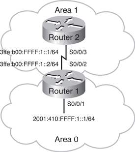
![]() Figure 8-28 shows an OSPFv3 network of two routers and two areas, area 0 and area 1, used for the first OSPFv3 example. The configuration of Router 1 is shown in Example 8-45, and the configuration of Router 2 is shown in Example 8-46. The interface-specific commands ipv6 ospf 100 area 0 and ipv6 ospf 100 area 1 create the “ipv6 router ospf 100” process dynamically. The area 0 range 2001:410::/32 command in Router 1 summarizes area 0’s routes to the 2001:410::/32 route.
Figure 8-28 shows an OSPFv3 network of two routers and two areas, area 0 and area 1, used for the first OSPFv3 example. The configuration of Router 1 is shown in Example 8-45, and the configuration of Router 2 is shown in Example 8-46. The interface-specific commands ipv6 ospf 100 area 0 and ipv6 ospf 100 area 1 create the “ipv6 router ospf 100” process dynamically. The area 0 range 2001:410::/32 command in Router 1 summarizes area 0’s routes to the 2001:410::/32 route.
ipv6 address 2001:410:FFFF:1::1/64
ipv6 ospf 100 area 0
!
interface Serial0/0/2
ipv6 address 3FFE:B00:FFFF:1::2/64
ipv6 ospf 100 area 1
!
ipv6 router ospf 100
router-id 10.1.1.3
area 0 range 2001:410::/32
ipv6 address 3FFE:B00:FFFF:1::1/64
ipv6 ospf 100 area 1
!
ipv6 router ospf 100
router-id 10.1.1.4
![]() Figure 8-29 illustrates a network used in our second OSPFv3 configuration example. This network has three areas.
Figure 8-29 illustrates a network used in our second OSPFv3 configuration example. This network has three areas.


![]() The top part of Example 8-47 illustrates the initial OSPFv3 configuration of the R1 router. IPv6 routing is first enabled with the ipv6 unicast-routing command, and then the S0/1/0 interface is configured to participate in OSPF process 1 in area 0 with the ipv6 ospf 1 area 0 command. The error message indicates that the router ID must be configured. In this router, no IPv4 addresses are configured, so the 32-bit router ID is configured with the router-id command. Notice that the router ID is set to the router number for simplicity. In the lower part of Example 8-47, R2 is configured similarly. Notice that the two neighbors form a FULL adjacency immediately after they are both configured.
The top part of Example 8-47 illustrates the initial OSPFv3 configuration of the R1 router. IPv6 routing is first enabled with the ipv6 unicast-routing command, and then the S0/1/0 interface is configured to participate in OSPF process 1 in area 0 with the ipv6 ospf 1 area 0 command. The error message indicates that the router ID must be configured. In this router, no IPv4 addresses are configured, so the 32-bit router ID is configured with the router-id command. Notice that the router ID is set to the router number for simplicity. In the lower part of Example 8-47, R2 is configured similarly. Notice that the two neighbors form a FULL adjacency immediately after they are both configured.
R1(config)#ipv6 unicast-routing
R1(config)#interface s0/1/0
R1(config-if)# ipv6 ospf 1 area 0
R1(config-if)#
*Aug 14 06:24:23.040: %OSPFv3-4-NORTRID: OSPFv3 process 1 could not pick a router-
id, please configure manually
R1(config-if)#exit
R1(config)#ipv6 router ospf 1
R1(config-rtr)#router-id 0.0.0.1
R1(config-rtr)#exit
R1(config)#interface s0/1/0
R1(config-if)#ipv6 ospf 1 area 0
R1(config-if)#


R2(config)#ipv6 unicast-routing
R2(config)#ipv6 router ospf 1
R2(config-rtr)#router-id 0.0.0.2
R2(config-rtr)#exit
R2(config)#interface s0/1/0
R2(config-if)#ipv6 ospf 1 area 0
*Aug 14 06:15:14.836: %OSPFv3-5-ADJCHG: Process 1, Nbr 0.0.0.1 on Serial0/1/0 from
LOADING to FULL, Loading Done
R2(config-if)#
![]() To verify the configuration, the show ipv6 ospf neighbor and show ipv6 ospf interface commands are used, as shown in Example 8-48. This output is from R2, and indicates that R2 has a FULL relationship with R1. Similar to OSPFv2, the link type is POINT_TO_POINT, and the hello and dead intervals are 10 and 40 seconds, respectively. Notice that for OSPFv3, the IPv6 link-local address is used for communication.
To verify the configuration, the show ipv6 ospf neighbor and show ipv6 ospf interface commands are used, as shown in Example 8-48. This output is from R2, and indicates that R2 has a FULL relationship with R1. Similar to OSPFv2, the link type is POINT_TO_POINT, and the hello and dead intervals are 10 and 40 seconds, respectively. Notice that for OSPFv3, the IPv6 link-local address is used for communication.
Neighbor ID Pri State Dead Time Interface ID Interface
0.0.0.1 1 FULL/ - 00.00.33 6 Serial0/1/0
R2(config-if)#
R2(config-if)#do show ipv6 ospf interface
Serial0/1/0 is up, line protocol is up
Link Local Address FE80::219:55FF:FE92:B212, Interface ID 6
Area 0, Process ID 1, Instance ID 0, Router ID 0.0.0.2
Network Type POINT_TO_POINT, Cost: 64
Transmit Delay is 1 sec, State POINT_TO_POINT,
Timer intervals configured, Hello 10, Dead 40, Wait 40, Retransmit 5
Hello due in 00:00:09
Index 1/1/1, flood queue length 0
Next 0x0(0)/0x0(0)/0x0(0)
Last flood scan length is 1, maximum is 2
Last flood scan time is 0 msec, maximum is 0 msec
Neighbor Count is 1, Adjacent neighbor count is 1
Adjacent with neighbor 0.0.0.1
Suppress hello for 0 neighbor(s)
R2(config-if)#
![]() In Example 8-49, area 24 is configured on R2 and R4, and the relationship between the two routers goes to the FULL state. The OSPF portion of R4’s routing table is also displayed, and includes the 12:12::/64 interarea route. This is the link between R1 and R2. (The 2001:1::/64 route is a global unicast address configured on R1.)
In Example 8-49, area 24 is configured on R2 and R4, and the relationship between the two routers goes to the FULL state. The OSPF portion of R4’s routing table is also displayed, and includes the 12:12::/64 interarea route. This is the link between R1 and R2. (The 2001:1::/64 route is a global unicast address configured on R1.)
R2(config-if)#ipv6 ospf 1 area 24
R2(config-if)#
R4(config)#ipv6 unicast-routing
R4(config)#ipv6 router ospf 1
R4(config-rtr)#router-id 0.0.0.4
R4(config-rtr)#exit
R4(config)#interface fa0/0
R4(config-if)#ipv6 ospf 1 area 24
*Aug 14 06:34:36.992: %OSPFv3-5-ADJCHG: Process 1, Nbr 0.0.0.2 on FastEthernet0/0
from LOADING to FULL, Loading Done
R4(config-if)#
R4(config-if)#do show ipv6 route ospf
IPv6 Routing Table – 6 entries
Codes: C – Connected, L – Local, S – Static, R – RIP, B – BGP
U – Per-user Static route
I1 – ISIS L1, I2 – ISIS L2, IA – ISIS interarea, IS – ISIS summary
O – OSPF intra, OI – OSPF inter, OE1 – OSPF ext 1, OE2 – OSPF ext 2
ON1 – OSPF NSSA ext 1, ON2 – OSPF NSSA ext 2
OI 12:12::/64 [110/65]
via FE80::219:55FF:FE92:B212, FastEthernet0/0
OI 2001:1::/64 [110/65]
via FE80::219:55FF:FE92:B212, FastEthernet0/0
R4(config-if)#
![]() In Example 8-50, area 13 is configured on R3 and on R1. The R3 routing table confirms that it has learned all appropriate routes, and a ping test is successfully conducted to verify connectivity from R3 to R4.
In Example 8-50, area 13 is configured on R3 and on R1. The R3 routing table confirms that it has learned all appropriate routes, and a ping test is successfully conducted to verify connectivity from R3 to R4.
R3(config)#ipv6 router ospf 1
R3(config)#
*Aug 14 06:24:09.976: %OSPFv3-4-NORTRID: OSPFv3 process 1 could not pick a
router-id, please configure manually
R3(config-rtr)#router-id 0.0.0.3
R3(config-rtr)#exit
R3(config)#interface fa0/0
R3(config-if)#ipv6 ospf 1 area 13
R3(config-if)#
R1(config-if)#interface fa0/0
R1(config-if)#ipv6 ospf 1 area 13
R1(config-if)#
*Aug 14 06:40:43.804: %OSPFv3-5-ADJCHG: Process 1, Nbr 0.0.0.3 on FastEthernet0/0
from LOADING to FULL, Loading Done
R1(config-if)#
R3#show ipv6 route ospf
IPv6 Routing Table – 7 entries
Codes: C – Connected, L – Local, S – Static, R – RIP, B – BGP
U – Per-user Static route
I1 – ISIS L1, I2 – ISIS L2, IA – ISIS interarea, IS – ISIS summary
O – OSPF intra, OI – OSPF inter, OE1 – OSPF ext 1, OE2 – OSPF ext 2
ON1 – OSPF NSSA ext 1, ON2 – OSPF NSSA ext 2
OI 12:12::/64 [110/65]
via FE80::219:56FF:FE2C:9F60, FastEthernet0/0
OI 24:24::/64 [110/66]
via FE80::219:56FF:FE2C:9F60, FastEthernet0/0
OI 2001:1::/64 [110/129]
via FE80::219:56FF:FE2C:9F60, FastEthernet0/0
R3#
R3#ping 24:24::4
Type escape sequence to abort.
Sending 5, 100-byte ICMP Echos to 24:24::4, timeout is 2 seconds:
!!!!!
Success rate is 100 percent (5/5), round-trip min/avg/max = 16/16/16 ms
R3#
![]() As mentioned, similar to OSPFv2, OSPFv3 can be customized to make the routing more efficient. For example, currently R3 has three routes, and they all go to R1, the ABR for area 13. Area 13 can be configured to be a totally stubby area since the area has only one ABR which it can use to get anywhere outside of the area. The configuration to do this, on R1 and R3, is the same as it is for OSPFv2, and is shown in Example 8-51. R1, the ABR, is configured with the area 13 stub no-summary command, and R3 is configured with the area 13 stub command. Just as in OSPFv2, the no-summary keyword is only required on the ABR. Notice that when R1 is configured, its adjacency with R3 is reset because the two routers do not agree on the stub area status of area 13. As soon as R3 is configured, the adjacency between the two routers becomes FULL again. Example 8-51 also shows the resulting routing table on R3. R3 now only has a default route (::/0), but it can still ping R4 successfully.
As mentioned, similar to OSPFv2, OSPFv3 can be customized to make the routing more efficient. For example, currently R3 has three routes, and they all go to R1, the ABR for area 13. Area 13 can be configured to be a totally stubby area since the area has only one ABR which it can use to get anywhere outside of the area. The configuration to do this, on R1 and R3, is the same as it is for OSPFv2, and is shown in Example 8-51. R1, the ABR, is configured with the area 13 stub no-summary command, and R3 is configured with the area 13 stub command. Just as in OSPFv2, the no-summary keyword is only required on the ABR. Notice that when R1 is configured, its adjacency with R3 is reset because the two routers do not agree on the stub area status of area 13. As soon as R3 is configured, the adjacency between the two routers becomes FULL again. Example 8-51 also shows the resulting routing table on R3. R3 now only has a default route (::/0), but it can still ping R4 successfully.
R1(config-rtr)#area 13 stub no-summary
R1(config-rtr)#
*Aug 14 06:54:11.780: %OSPFv3-5-ADJCHG: Process 1, Nbr 0.0.0.3 on
FastEthernet0/0 from FULL to DOWN, Neighbor Down: Adjacency forced to reset
R1(config-rtr)#
R3(config)#ipv6 router ospf 1
R3(config-rtr)#area 13 stub
R3(config-rtr)#
*Aug 14 06:40:17.716: %OSPFv3-5-ADJCHG: Process 1, Nbr 0.0.0.1 on
FastEthernet0/0 from LOADING to FULL, Loading Done
R3(config-rtr)#
R3#show ipv6 route ospf
IPv6 Routing Table – 5 entries
Codes: C – Connected, L – Local, S – Static, R – RIP, B – BGP
U – Per-user Static route
I1 – ISIS L1, I2 – ISIS L2, IA – ISIS interarea, IS – ISIS summary
O – OSPF intra, OI – OSPF inter, OE1 – OSPF ext 1, OE2 – OSPF ext 2
ON1 – OSPF NSSA ext 1, ON2 – OSPF NSSA ext 2
OI ::/0 [110/2]
via FE80::219:56FF:FE2C:9F60, FastEthernet0/0
R3#
R3#ping 24:24::4
Type escape sequence to abort.
Sending 5, 100-byte ICMP Echos to 24:24::4, timeout is 2 seconds:
!!!!!
Success rate is 100 percent (5/5), round-trip min/avg/max = 12/14/16 ms
R3#
EIGRP for IPv6
![]() EIGRP for IPv6 is available in Cisco IOS Release 12.4(6)T and later. EIGRP for IPv4 and EIGRP for IPv6 are configured and managed separately. However, the configuration and operation of EIGRP for IPv4 and IPv6 is similar.
EIGRP for IPv6 is available in Cisco IOS Release 12.4(6)T and later. EIGRP for IPv4 and EIGRP for IPv6 are configured and managed separately. However, the configuration and operation of EIGRP for IPv4 and IPv6 is similar.
![]() EIGRP for IPv6 uses the same protocol number (88) as EIGRP for IPv4 does, and it includes all the same features, including keeping neighbor routing table information in a topology table, and using queries if no feasible successors are available.
EIGRP for IPv6 uses the same protocol number (88) as EIGRP for IPv4 does, and it includes all the same features, including keeping neighbor routing table information in a topology table, and using queries if no feasible successors are available.
![]() A router ID is required for EIGRP for IPv6 configuration. Similar to OSPFv3, the router ID is a 32-bit IPv4 address. In an IPv6-only environment, there are no IPv4 addresses assigned, so the router ID must be configured manually.
A router ID is required for EIGRP for IPv6 configuration. Similar to OSPFv3, the router ID is a 32-bit IPv4 address. In an IPv6-only environment, there are no IPv4 addresses assigned, so the router ID must be configured manually.
![]() EIGRP for IPv6 is configured on a per-interface basis, similar to OSPFv3; the network command is not used. And, also similar to OSPFv3, link-local addressing is used for establishing neighbor adjacencies. Therefore, for EIGRP for IPv6, it is possible for routers to become neighbors even if they do not have global unicast addresses assigned.
EIGRP for IPv6 is configured on a per-interface basis, similar to OSPFv3; the network command is not used. And, also similar to OSPFv3, link-local addressing is used for establishing neighbor adjacencies. Therefore, for EIGRP for IPv6, it is possible for routers to become neighbors even if they do not have global unicast addresses assigned.
![]() The EIGRP for IPv6 routing protocol has a shutdown feature, and in fact it starts in this state.
The EIGRP for IPv6 routing protocol has a shutdown feature, and in fact it starts in this state.
![]() EIGRP for IPv4 automatically summarizes on classful network boundaries. This is not the case with EIGRP for IPv6; it does not automatically summarize.
EIGRP for IPv4 automatically summarizes on classful network boundaries. This is not the case with EIGRP for IPv6; it does not automatically summarize.
EIGRP for IPv6 Configuration and Verification Commands
![]() Many of the EIGRP for IPv6 commands are similar to their EIGRP for IPv4 counterparts, with the ip keyword replaced by the ipv6 keyword.
Many of the EIGRP for IPv6 commands are similar to their EIGRP for IPv4 counterparts, with the ip keyword replaced by the ipv6 keyword.
![]() The ipv6 eigrp as-number interface configuration command enables EIGRP for IPv6 on an interface. The as-number parameter identifies the EIGRP autonomous system (AS) that the interface participates in.
The ipv6 eigrp as-number interface configuration command enables EIGRP for IPv6 on an interface. The as-number parameter identifies the EIGRP autonomous system (AS) that the interface participates in.
![]() The ipv6 router eigrp as-number global configuration command creates an EIGRP for IPv6 routing process and puts the router in router configuration mode.
The ipv6 router eigrp as-number global configuration command creates an EIGRP for IPv6 routing process and puts the router in router configuration mode.
![]() The eigrp router-id {ip-address} router configuration command defines a router ID for EIGRP for IPv6. The ip-address is a number in IPv4 address format; in other words it is a 32-bit number in dotted-decimal format. The router ID must be unique on each router.
The eigrp router-id {ip-address} router configuration command defines a router ID for EIGRP for IPv6. The ip-address is a number in IPv4 address format; in other words it is a 32-bit number in dotted-decimal format. The router ID must be unique on each router.
| Note |
|
![]() The no shutdown router configuration command enables the EIGRP process.
The no shutdown router configuration command enables the EIGRP process.
| Note |
|
![]() Similar to EIGRP for IPv4, use the eigrp stub [receive-only | connected | static | summary | redistributed] router configuration command to configure a router as an EIGRP stub.
Similar to EIGRP for IPv4, use the eigrp stub [receive-only | connected | static | summary | redistributed] router configuration command to configure a router as an EIGRP stub.
| Note |
|
![]() The ipv6 summary-address eigrp as-number ipv6-address [admin-distance] interface configuration command configures a summary aggregate address for an interface. Table 8-9 describes the parameters of this command.
The ipv6 summary-address eigrp as-number ipv6-address [admin-distance] interface configuration command configures a summary aggregate address for an interface. Table 8-9 describes the parameters of this command.
|
|
|
|---|---|
|
|
|
|
|
|
|
|
|
EIGRP for IPv6 Configuration and Verification Example
![]() Figure 8-30 illustrates the network used to examine EIGRP for IPv6 configuration and verification. All interfaces have IPv6 addresses, including the three loopback interfaces on R3.
Figure 8-30 illustrates the network used to examine EIGRP for IPv6 configuration and verification. All interfaces have IPv6 addresses, including the three loopback interfaces on R3.


![]() Example 8-52 shows the configuration of R1 and R3 for EIGRP for IPv6. The ipv6 unicast-routing command is configured on each router. On each interface (including the loopback interfaces on R3) the ipv6 eigrp 100 command is enabled; 100 is the EIGRP autonomous system number. Recall that this must be the same on all routers for them to communicate.
Example 8-52 shows the configuration of R1 and R3 for EIGRP for IPv6. The ipv6 unicast-routing command is configured on each router. On each interface (including the loopback interfaces on R3) the ipv6 eigrp 100 command is enabled; 100 is the EIGRP autonomous system number. Recall that this must be the same on all routers for them to communicate.
R1(config)#ipv6 unicast-routing
R1(config)#interface Serial0/0/0.2 point-to-point
R1(config-subif)#ipv6 eigrp 100
R1(config-subif)#interface Serial0/0/0.3 point-to-point
R1(config-subif)#ipv6 eigrp 100
R1(config-subif)#exit
R1(config)#


R3(config)#ipv6 unicast-routing
R3(config)#interface Serial0/0/0.1 point-to-point
R3(config-subif)#ipv6 eigrp 100
R3(config-subif)#interface loopback 301
R3(config-if)#ipv6 eigrp 100
R3(config-if)#interface loopback 302
R3(config-if)#ipv6 eigrp 100
R3(config-if)#interface loopback 303
R3(config-if)#ipv6 eigrp 100
R3(config-if)#
![]() No messages are displayed on the router’s console indicating that EIGRP neighbor relationships have established. The show ipv6 eigrp neighbor command output, provided at the top of Example 8-53 indicates why: EIGRP 100 is shut down. For IPv6, the EIGRP process must be enabled, with the no shutdown command. This is configured on both R1 and R3, as also shown in the example.
No messages are displayed on the router’s console indicating that EIGRP neighbor relationships have established. The show ipv6 eigrp neighbor command output, provided at the top of Example 8-53 indicates why: EIGRP 100 is shut down. For IPv6, the EIGRP process must be enabled, with the no shutdown command. This is configured on both R1 and R3, as also shown in the example.
IPv6-EIGRP neighbors for process 100
% EIGRP 100 is in SHUTDOWN
R3(config-if)#exit
R3(config)#ipv6 router eigrp 100
R3(config-rtr)#no shutdown
R1(config)#ipv6 router eigrp 100
R1(config-rtr)#no shutdown
R1(config-rtr)#
![]() However, an adjacency is still not established. Example 8-54 illustrates the output of the show ipv6 eigrp neighbor command on R3. This time the problem is that there is no router ID defined. Example 8-54 also shows the configuration of the router ID on both routers. The neighbor relationship immediately comes up. The EIGRP portion of R1’s routing table is shown in the example; R3’s loopback interface addresses have been learned. Notice that, unlike EIGRP for IPv4, the networks are not automatically summarized.
However, an adjacency is still not established. Example 8-54 illustrates the output of the show ipv6 eigrp neighbor command on R3. This time the problem is that there is no router ID defined. Example 8-54 also shows the configuration of the router ID on both routers. The neighbor relationship immediately comes up. The EIGRP portion of R1’s routing table is shown in the example; R3’s loopback interface addresses have been learned. Notice that, unlike EIGRP for IPv4, the networks are not automatically summarized.
R3(config)#do show ipv6 eigrp neighbor
IPv6-EIGRP neighbors for process 100
% No router ID for EIGRP 100
R3(config-rtr)#eigrp router-id 3.3.3.3
R3(config-rtr)#


R1(config-rtr)#eigrp router-id 1.1.1.1
R1(config-rtr)#
%DUAL-5-NBRCHANGE: IPv6-EIGRP(0) 100: Neighbor FE80::3 (Serial0/0/0.3) is up: new
adjacency
R1(config-rtr)#do show ipv6 route eigrp
IPv6 Routing Table – 9 entries
Codes: C – Connected, L – Local, S – Static, R – RIP, B – BGP
      U – Per-user Static route
      I1 – ISIS L1, I2 – ISIS L2, IA – ISIS interarea, IS – ISIS summary
      O – OSPF intra, OI – OSPF inter, OE1 – OSPF ext 1, OE2 – OSPF ext 2
      ON1 – OSPF NSSA ext 1, ON2 – OSPF NSSA ext 2
      D – EIGRP, EX – EIGRP external
D    3:1::/64 [90/2297856]
     via FE80::3, Serial0/0/0.3
D    3:2::/64 [90/2297856]
     via FE80::3, Serial0/0/0.3
D    3:3::/64 [90/2297856]
     via FE80::3, Serial0/0/0.3
R1(config-rtr)#
![]() Routers R2 and R4 are configured similarly, as shown in Example 8-55.
Routers R2 and R4 are configured similarly, as shown in Example 8-55.
R2(config)#ipv6 unicast-routing
R2(config)#!
R2(config)#interface Serial0/0/0.1 point-to-point
R2(config-subif)#ipv6 eigrp 100
R2(config-subif)#interface Serial0/0/0.4 point-to-point
R2(config-subif)#ipv6 eigrp 100
R2(config-subif)#ipv6 router eigrp 100
R2(config-rtr)#eigrp router-id 2.2.2.2
R2(config-rtr)#no shutdown
R2(config-rtr)#
%DUAL-5-NBRCHANGE: IPv6-EIGRP(0) 100: Neighbor FE80::1 (Serial0/0/0.1) is up: new
adjacency
R2(config-rtr)#


R4(config)#ipv6 unicast-routing
R4(config)#interface Serial0/0/0.2 point-to-point
R4(config-subif)#ipv6 eigrp 100
R4(config-subif)#ipv6 router eigrp 100
R4(config-rtr)#eigrp router-id 4.4.4.4
R4(config-rtr)#no shutdown
%DUAL-5-NBRCHANGE: IPv6-EIGRP(0) 100: Neighbor FE80::2 (Serial0/0/0.2) is up: new
adjacency
R4(config-rtr)#
![]() R4’s routing table contains the appropriate routes, including to R3’s loopback addresses, as shown Example 8-56. The successful ping from R4 to one of these loopbacks is also illustrated.
R4’s routing table contains the appropriate routes, including to R3’s loopback addresses, as shown Example 8-56. The successful ping from R4 to one of these loopbacks is also illustrated.
R4(config-rtr)#do show ipv6 route eigrp
IPv6 Routing Table – 9 entries
Codes: C – Connected, L – Local, S – Static, R – RIP, B – BGP
      U – Per-user Static route
      I1 – ISIS L1, I2 – ISIS L2, IA – ISIS interarea, IS – ISIS summary
      O – OSPF intra, OI – OSPF inter, OE1 – OSPF ext 1, OE2 – OSPF ext 2
      ON1 – OSPF NSSA ext 1, ON2 – OSPF NSSA ext 2
      D – EIGRP, EX – EIGRP external
D    3:1::/64 [90/3321856]
     via FE80::2, Serial0/0/0.2
D    3:2::/64 [90/3321856]
     via FE80::2, Serial0/0/0.2
D    3:3::/64 [90/3321856]
     via FE80::2, Serial0/0/0.2
D    12::/64 [90/2681856]
     via FE80::2, Serial0/0/0.2
D    13::/64 [90/3193856]
     via FE80::2, Serial0/0/0.2
R4(config-rtr)#do ping 3:1::3
Type escape sequence to abort.
Sending 5, 100-byte ICMP Echos to 3:1::3, timeout is 2 seconds:
!!!!!
Success rate is 100 percent (5/5), round-trip min/avg/max = 88/88/88 ms
R4(config-rtr)#
![]() As mentioned, EIGRP for IPv6 supports many other features. To illustrate the stub routing feature, EIGRP event debugging is enabled on R4 with the debug ipv6 eigrp command, and then the first loopback interface on R3 is shut down, as shown in Example 8-57. The resulting debug output is shown. Notice that a query packet about the lost route goes from R3 all the way to R4.
As mentioned, EIGRP for IPv6 supports many other features. To illustrate the stub routing feature, EIGRP event debugging is enabled on R4 with the debug ipv6 eigrp command, and then the first loopback interface on R3 is shut down, as shown in Example 8-57. The resulting debug output is shown. Notice that a query packet about the lost route goes from R3 all the way to R4.
R4(config-rtr)#do debug ipv6 eigrp
IP-EIGRP Route Events debugging is on
R4(config-rtr)#


R3(config-if)#interface loopback 301
R3(config-if)#shutdown
R3(config-if)#


R4(config-rtr)#
IPv6-EIGRP(0:100): Processing incoming QUERY packet
IPv6-EIGRP(0:100): Int 3:1::/64 M 4294967295 – 0 4294967295 SM 4294967295 - 0
4294967295
IPv6-EIGRP(0:100): 3:1::/64 deleted FE80::2(FE80::2)/Serial0/0/0.2
IPv6-EIGRP(0:100): 3:1::/64 (90/-1) added to RIB
IPv6-EIGRP(0:100): 3:1::/64 – do advertise out Serial0/0/0.2
IPv6-EIGRP(0:100): Int 3:1::/64 metric 4294967295 – 0 4294967295
IPv6-EIGRP(0:100): 3:1::/64 deleted FE80::2(FE80::2)/Serial0/0/0.2
IPv6-EIGRP(0:100): 3:1::/64 – not in IPv6 routing table
IPv6-EIGRP(0:100): Int 3:1::/64 metric 4294967295 – 0 4294967295
IPv6-EIGRP(0:100): Processing incoming UPDATE packet
IPv6-EIGRP(0:100): Int 3:1::/64 M 4294967295 – 0 4294967295 SM 4294967295 - 0
4294967295
![]() Recall from Chapter 2 that with the EIGRP stub routing feature, a stub router indicates in its hello packet to all neighboring routers its status as a stub router. Any router that receives a packet informing it of its neighbor’s stub status does not query the stub router for any routes. Therefore, a router that has a stub peer does not query that peer. Instead the router connected to the stub router answers the query on behalf of the stub router. Because R4 is a stub router, it should be configured as such, to stop unnecessary queries going to it. Example 8-58 illustrates the configuration of R4 as a stub, and the resulting debug output. (The stub command is used on R4 in this example; recall that the newer version of this command, eigrp stub, could have been used.) As soon as the stub command is entered, the EIGRP peer is reset and the router processes all the EIGRP updates again.
Recall from Chapter 2 that with the EIGRP stub routing feature, a stub router indicates in its hello packet to all neighboring routers its status as a stub router. Any router that receives a packet informing it of its neighbor’s stub status does not query the stub router for any routes. Therefore, a router that has a stub peer does not query that peer. Instead the router connected to the stub router answers the query on behalf of the stub router. Because R4 is a stub router, it should be configured as such, to stop unnecessary queries going to it. Example 8-58 illustrates the configuration of R4 as a stub, and the resulting debug output. (The stub command is used on R4 in this example; recall that the newer version of this command, eigrp stub, could have been used.) As soon as the stub command is entered, the EIGRP peer is reset and the router processes all the EIGRP updates again.
R4(config-rtr)#stub
%DUAL-5-NBRCHANGE: IPv6-EIGRP(0) 100: Neighbor FE80::2 (Serial0/0/0.2) is down: peer
info changed
R4(config-rtr)#
IPv6-EIGRP(0:100): 3:3::/64 deleted FE80::2(FE80::2)/Serial0/0/0.2
IPv6-EIGRP(0:100): 3:2::/64 deleted FE80::2(FE80::2)/Serial0/0/0.2
IPv6-EIGRP(0:100): 12::/64 deleted FE80::2(FE80::2)/Serial0/0/0.2
IPv6-EIGRP(0:100): 13::/64 deleted FE80::2(FE80::2)/Serial0/0/0.2
%DUAL-5-NBRCHANGE: IPv6-EIGRP(0) 100: Neighbor FE80::2 (Serial0/0/0.2) is up: new
adjacency
IPv6-EIGRP(0:100): Processing incoming UPDATE packet
IPv6-EIGRP(0:100): Processing incoming UPDATE packet
IPv6-EIGRP(0:100): Int 12::/64 M 2681856 – 1657856 1024000 SM 2169856 – 1657856
512000
IPv6-EIGRP(0:100): 12::/64 (90/2681856) added to RIB
IPv6-EIGRP(0:100): Int 24::/64 M 2681856 – 1657856 1024000 SM 2169856 – 1657856
512000
IPv6-EIGRP(0:100): 24::/64 routing table not updated
IPv6-EIGRP(0:100): Int 13::/64 M 3193856 – 1657856 1536000 SM 2681856 – 1657856
1024000
IPv6-EIGRP(0:100): 13::/64 (90/3193856) added to RIB
IPv6-EIGRP(0:100): Int 3:2::/64 M 3321856 – 1657856 1664000 SM 2809856 – 1657856
1152000
IPv6-EIGRP(0:100): 3:2::/64 (90/3321856) added to RIB
IPv6-EIGRP(0:100): Int 3:3::/64 M 3321856 – 1657856 1664000 SM 2809856 – 1657856
1152000
IPv6-EIGRP(0:100): 3:3::/64 (90/3321856) added to RIB
IPv6-EIGRP(0:100): 24::/64 – do advertise out Serial0/0/0.2
IPv6-EIGRP(0:100): Int 24::/64 metric 2169856 – 1657856 512000
R4(config-rtr)#
![]() To confirm that the stub configuration is working, the R3 loopback interface is enabled and then disabled again. This process and the resulting debug output on R4 are illustrated in Example 8-59. Notice that there are no queries; only an update and a reply message are received, telling R4 about the deleted route.
To confirm that the stub configuration is working, the R3 loopback interface is enabled and then disabled again. This process and the resulting debug output on R4 are illustrated in Example 8-59. Notice that there are no queries; only an update and a reply message are received, telling R4 about the deleted route.
R3(config-if)#no shutdown
R3(config-if)#shutdown


R4(config-rtr)#
IPv6-EIGRP(0:100): Processing incoming UPDATE packet
IPv6-EIGRP(0:100): Int 3:1::/64 M 4294967295 – 0 4294967295 SM 4294967295 - 0
4294967295
IPv6-EIGRP(0:100): Int 3:1::/64 metric 4294967295 – 0 4294967295
IPv6-EIGRP(0:100): Processing incoming REPLY packet
IPv6-EIGRP(0:100): Int 3:1::/64 M 4294967295 – 0 4294967295 SM 4294967295 - 0
4294967295
IPv6-EIGRP(0:100): 3:1::/64 deleted FE80::2(FE80::2)/Serial0/0/0.2
R4(config-rtr)#
![]() Another feature supported by EIGRP for IPv6 is route summarization. As we have seen, this protocol does not automatically summarize, but properly configured summarization is useful for fault isolation and performance optimization, and results in a more stable network. In the example, summarization of the three loopback interface networks on R3 is configured with the ipv6 summary address eigrp 100 3::/16 command. The configuration is shown in Example 8-60. Notice that the neighbor adjacency is reset immediately. The resulting debug output on R4 and the R4 routing table is also shown. As expected, the routing table contains the summary of the three loopback addresses, not the addresses themselves.
Another feature supported by EIGRP for IPv6 is route summarization. As we have seen, this protocol does not automatically summarize, but properly configured summarization is useful for fault isolation and performance optimization, and results in a more stable network. In the example, summarization of the three loopback interface networks on R3 is configured with the ipv6 summary address eigrp 100 3::/16 command. The configuration is shown in Example 8-60. Notice that the neighbor adjacency is reset immediately. The resulting debug output on R4 and the R4 routing table is also shown. As expected, the routing table contains the summary of the three loopback addresses, not the addresses themselves.
R3(config-subif)#ipv6 summary-address eigrp 100 3::/16
R3(config-subif)#
%DUAL-5-NBRCHANGE: IPv6-EIGRP(0) 100: Neighbor FE80::1 (Serial0/0/0.1) is down:
summary configured
%DUAL-5-NBRCHANGE: IPv6-EIGRP(0) 100: Neighbor FE80::1 (Serial0/0/0.1) is up: new
adjacency
R4(config-rtr)#
IPv6-EIGRP(0:100): Int 3:3::/64 metric 4294967295 –1657856 4294967295
IPv6-EIGRP(0:100): Int 3:2::/64 metric 4294967295 –1657856 4294967295
IPv6-EIGRP(0:100): Processing incoming REPLY packet
IPv6-EIGRP(0:100): Int 3:3::/64 M 4294967295 – 1657856 4294967295 SM 4294967295 –
1657856 4294967295
IPv6-EIGRP(0:100): 3:3::/64 deleted FE80::2(FE80::2)/Serial0/0/0.2
IPv6-EIGRP(0:100): Int 3:2::/64 M 4294967295 – 1657856 4294967295 SM 4294967295 –
1657856 4294967295
IPv6-EIGRP(0:100): 3:2::/64 deleted FE80::2(FE80::2)/Serial0/0/0.2
IPv6-EIGRP(0:100): Processing incoming UPDATE packet
IPv6-EIGRP(0:100): Int 3::/16 M 3321856 – 1657856 1664000 SM 2809856 – 1657856
1152000
IPv6-EIGRP(0:100): 3::/16 (90/3321856) added to RIB
R4(config-rtr)#
R4(config-rtr)#do show ipv6 route eigrp
IPv6 Routing Table – 7 entries
Codes: C – Connected, L – Local, S – Static, R – RIP, B – BGP
U – Per-user Static route
I1 – ISIS L1, I2 – ISIS L2, IA – ISIS interarea, IS – ISIS summary
O – OSPF intra, OI – OSPF inter, OE1 – OSPF ext 1, OE2 – OSPF ext 2
ON1 – OSPF NSSA ext 1, ON2 – OSPF NSSA ext 2
D – EIGRP, EX – EIGRP external
D 3::/16 [90/3321856]
via FE80::2, Serial0/0/0.2
D 12::/64 [90/2681856]
via FE80::2, Serial0/00.2
D 13::/64 [90/3193856]
via FE80::2, Serial0/0/0.2
R4(config-rtr)#
![]() If you wanted to illustrate how summarization helps with fault isolation, one of the loopback interfaces on R3 could be shutdown, and then enabled. No messages would appear on R4, illustrating that by summarizing, the scope of the failure domain would be reduced, and the routing overhead and routing table size would be decreased.
If you wanted to illustrate how summarization helps with fault isolation, one of the loopback interfaces on R3 could be shutdown, and then enabled. No messages would appear on R4, illustrating that by summarizing, the scope of the failure domain would be reduced, and the routing overhead and routing table size would be decreased.
MBGP
![]() To make Border Gateway Protocol Version 4 (BGP-4) available for other network layer protocols, including Multiprotocol Label Switching (MPLS) virtual private network (VPN) and IPv6, RFC 4760 defines multiprotocol extensions for BGP-4. RFC 2545 defines how these extensions are used for IPv6.
To make Border Gateway Protocol Version 4 (BGP-4) available for other network layer protocols, including Multiprotocol Label Switching (MPLS) virtual private network (VPN) and IPv6, RFC 4760 defines multiprotocol extensions for BGP-4. RFC 2545 defines how these extensions are used for IPv6.
![]() IPv6-specific extensions incorporated into MBGP include the following:
IPv6-specific extensions incorporated into MBGP include the following:
- A new identifier for the IPv6 address family.
- Scoped addresses—The NEXT_HOP attribute contains a global IPv6 address and potentially a link-local address (only when there is link-local reachability with the peer).
- The NEXT_HOP and Network Layer Reachability Information (NLRI) attributes are expressed as IPv6 addresses and prefixes. (The NLRI field in a BGP update message lists the networks reachable on the BGP path described by the update message.)
![]() MBGP can of course operate with multiple protocols. It operates by identifying two separate protocols: the carrier protocol and the passenger protocol.
MBGP can of course operate with multiple protocols. It operates by identifying two separate protocols: the carrier protocol and the passenger protocol.
![]() In an all-IPv4 environment, BGP establishes sessions using IPv4 (using TCP port 179); IPv4 is the carrier protocol. The routes that BGP advertises are also IPv4. Therefore, IPv4 is also the passenger protocol. This scenario is illustrated in Figure 8-31.
In an all-IPv4 environment, BGP establishes sessions using IPv4 (using TCP port 179); IPv4 is the carrier protocol. The routes that BGP advertises are also IPv4. Therefore, IPv4 is also the passenger protocol. This scenario is illustrated in Figure 8-31.


![]() Protocols other than IPv4, including MPLS VPN, multicast, and IPv6, also need to advertise reachability information. MBGP extensions to allow these other protocols to be carried using BGP. An analogy is that BGP is a truck that can transport multiple payloads. For example, the BGP “truck” could be IPv4 and it could be used to transport IPv6 (or other protocol) “payloads.” In this case, the carrier protocol is IPv4 and the passenger protocol is IPv6, the IPv6 prefixes being advertised. This scenario is illustrated in Figure 8-32.
Protocols other than IPv4, including MPLS VPN, multicast, and IPv6, also need to advertise reachability information. MBGP extensions to allow these other protocols to be carried using BGP. An analogy is that BGP is a truck that can transport multiple payloads. For example, the BGP “truck” could be IPv4 and it could be used to transport IPv6 (or other protocol) “payloads.” In this case, the carrier protocol is IPv4 and the passenger protocol is IPv6, the IPv6 prefixes being advertised. This scenario is illustrated in Figure 8-32.


![]() In an all IPv6 environment, BGP can be used as both the carrier and passenger protocol, as illustrated in Figure 8-33. In this case, IPv6 is used to establish BGP sessions, and BGP advertises IPv6 prefixes; both the truck and the payload are IPv6.
In an all IPv6 environment, BGP can be used as both the carrier and passenger protocol, as illustrated in Figure 8-33. In this case, IPv6 is used to establish BGP sessions, and BGP advertises IPv6 prefixes; both the truck and the payload are IPv6.


![]() IPv6 routes are carried with the use of the MBGP extension IPv6 NLRI, which defines a new address family that can be advertised using MBGP. Each protocol that uses MBGP has an address family defined.
IPv6 routes are carried with the use of the MBGP extension IPv6 NLRI, which defines a new address family that can be advertised using MBGP. Each protocol that uses MBGP has an address family defined.
| Note |
|
MBGP Configuration and Verification Commands
![]() MBGP for IPv6 is configured similarly to configuring BGP for IPv4, as explored in Chapter 6, “Implementing a Border Gateway Protocol Solution for ISP Connectivity.”
MBGP for IPv6 is configured similarly to configuring BGP for IPv4, as explored in Chapter 6, “Implementing a Border Gateway Protocol Solution for ISP Connectivity.”
![]() The same router bgp autonomous-system global configuration command is used to enter BGP configuration mode, and identify the local autonomous system in which this router belongs. The autonomous-system parameter identifies the local autonomous system.
The same router bgp autonomous-system global configuration command is used to enter BGP configuration mode, and identify the local autonomous system in which this router belongs. The autonomous-system parameter identifies the local autonomous system.
![]() The bgp router-id ip-address router configuration command configures a fixed router ID for the local BGP routing process. The ip-address parameter is an IPv4-address format 32-bit dotted-decimal number. This command is required in an IPv6-only network.
The bgp router-id ip-address router configuration command configures a fixed router ID for the local BGP routing process. The ip-address parameter is an IPv4-address format 32-bit dotted-decimal number. This command is required in an IPv6-only network.
![]() The neighbor {ipv6-address | peer-group-name} remote-as autonomous-system-number router configuration command is similar to its IPv4 counterpart and is used to activate a BGP session for external and internal neighbors and to identify a peer router with which the local router will establish a session. The router runs internal BGP (IBGP) with internal neighbors and external BGP (EBGP) with external neighbors. The parameters in this command are described in Table 8-10.
The neighbor {ipv6-address | peer-group-name} remote-as autonomous-system-number router configuration command is similar to its IPv4 counterpart and is used to activate a BGP session for external and internal neighbors and to identify a peer router with which the local router will establish a session. The router runs internal BGP (IBGP) with internal neighbors and external BGP (EBGP) with external neighbors. The parameters in this command are described in Table 8-10.
|
| |
|---|---|
|
|
|
|
|
|
|
|
|
![]() The address-family ipv6 [unicast | multicast | vpnv6] router configuration command enters address family configuration mode for configuring BGP routing sessions that use IPv6 address prefixes. The parameters in this command are described in Table 8-11.
The address-family ipv6 [unicast | multicast | vpnv6] router configuration command enters address family configuration mode for configuring BGP routing sessions that use IPv6 address prefixes. The parameters in this command are described in Table 8-11.
|
|
|
|---|---|
|
|
|
|
|
|
|
|
|
![]() The neighbor ipv6-address activate address family configuration (or router configuration) command enables the exchange of information with a BGP neighbor. The ipv6-address is the IPv6 address of the neighbor.
The neighbor ipv6-address activate address family configuration (or router configuration) command enables the exchange of information with a BGP neighbor. The ipv6-address is the IPv6 address of the neighbor.
![]() The same network network-number address family configuration (or router configuration) command is used to specify the networks to be advertised by the BGP and MBGP routing process in the network-number parameter.
The same network network-number address family configuration (or router configuration) command is used to specify the networks to be advertised by the BGP and MBGP routing process in the network-number parameter.
![]() To apply a route map to filter incoming or outgoing MBGP routes, use the similar neighbor ipv6-address route-map name {in | out} address family configuration (or router configuration) command. The routes that are permitted may have their attributes set or changed, using set commands in the route map. This is useful when trying to influence route selection.
To apply a route map to filter incoming or outgoing MBGP routes, use the similar neighbor ipv6-address route-map name {in | out} address family configuration (or router configuration) command. The routes that are permitted may have their attributes set or changed, using set commands in the route map. This is useful when trying to influence route selection.
MBGP Configuration and Verification Example
![]() Example 8-61 illustrates an example configuration of a router with one MBGP neighbor. The first section of the router bgp configuration defines a 32-bit router ID (which must be configured in an IPv6-only network) and establishes the BGP peering session with the neighbor to send and receive advertisements. In this example, the peering session is established using IPv6, so IPv6 is the carrier protocol. The second section of the configuration starts with the address-family ipv6 command; it defines the passenger protocol, the protocol that is to be advertised using MBGP. In this example, the passenger protocol is IPv6. All passenger protocols have an address family section within the router bgp configuration. The address family section is where routing policies and specific features for the particular address family are defined. In this example, the neighbor is activated (as it must be for each address family) and redistribution is configured.
Example 8-61 illustrates an example configuration of a router with one MBGP neighbor. The first section of the router bgp configuration defines a 32-bit router ID (which must be configured in an IPv6-only network) and establishes the BGP peering session with the neighbor to send and receive advertisements. In this example, the peering session is established using IPv6, so IPv6 is the carrier protocol. The second section of the configuration starts with the address-family ipv6 command; it defines the passenger protocol, the protocol that is to be advertised using MBGP. In this example, the passenger protocol is IPv6. All passenger protocols have an address family section within the router bgp configuration. The address family section is where routing policies and specific features for the particular address family are defined. In this example, the neighbor is activated (as it must be for each address family) and redistribution is configured.
bgp router-id 1.1.1.1
neighbor 2001:100:2:4::1 remote-as 100
!
address-family ipv6
neighbor 2001:100:2:4::1 activate
redistribute connected
| Note |
|
IPv6 Policy-Based Routing
![]() As described in Chapter 4, “Manipulating Routing Updates,” policy-based routing (PBR) allows the network administrator to define a routing policy other than destination-based routing using the routing table. PBR is sometimes called traffic engineering and helps to provide a high degree of control over routing. PBR is available for both IPv4 and IPv6.
As described in Chapter 4, “Manipulating Routing Updates,” policy-based routing (PBR) allows the network administrator to define a routing policy other than destination-based routing using the routing table. PBR is sometimes called traffic engineering and helps to provide a high degree of control over routing. PBR is available for both IPv4 and IPv6.
![]() PBR can be used for manually configuring the path that packets will take. It can also be used to classify and mark packets. As is the case for IPv4, IPv6 PBR is based on match commands for identifying the traffic to be policy-based routed, and set commands for defining how that traffic will be routed.
PBR can be used for manually configuring the path that packets will take. It can also be used to classify and mark packets. As is the case for IPv4, IPv6 PBR is based on match commands for identifying the traffic to be policy-based routed, and set commands for defining how that traffic will be routed.
IPv6 PBR Configuration and Verification Commands
![]() Many of the commands used for IPv6 PBR are the same as or similar to their IPv4 counterparts, some with the ip keyword replaced by the ipv6 keyword.
Many of the commands used for IPv6 PBR are the same as or similar to their IPv4 counterparts, some with the ip keyword replaced by the ipv6 keyword.
![]() The route-map map-tag [permit | deny] [sequence-number] global configuration command is the same as the IPv4 command explained in Chapter 4. It creates a route map. The parameters of this command are explained again in detail in Table 8-12.
The route-map map-tag [permit | deny] [sequence-number] global configuration command is the same as the IPv4 command explained in Chapter 4. It creates a route map. The parameters of this command are explained again in detail in Table 8-12.
|
|
|
|---|---|
|
|
|
|
|
|
|
|
|
![]() The default for the route-map command is permit, with a sequence-number of 10.
The default for the route-map command is permit, with a sequence-number of 10.
![]() Recall that if you leave out the sequence number when configuring all statements for the same route map name, the router will assume that you are editing (and possibly adding to) the first statement, which defaults to sequence number 10. Route map sequence numbers do not automatically increment!
Recall that if you leave out the sequence number when configuring all statements for the same route map name, the router will assume that you are editing (and possibly adding to) the first statement, which defaults to sequence number 10. Route map sequence numbers do not automatically increment!
![]() A route map can refer to many match and set commands. This section provides only one of each, and in the next section provides an example that uses these two commands.
A route map can refer to many match and set commands. This section provides only one of each, and in the next section provides an example that uses these two commands.
![]() The match ipv6 address {prefix-list prefix-list-name | access-list-name} route-map configuration command specifies a prefix permitted by a prefix list to use in redistribution or an IPv6 access list to use to match packets for PBR for IPv6. The prefix-list-name specifies the name of the prefix list, and the access-list-name parameter specifies the name of the access list.
The match ipv6 address {prefix-list prefix-list-name | access-list-name} route-map configuration command specifies a prefix permitted by a prefix list to use in redistribution or an IPv6 access list to use to match packets for PBR for IPv6. The prefix-list-name specifies the name of the prefix list, and the access-list-name parameter specifies the name of the access list.
![]() The set ipv6 next-hop global-ipv6-address [global-ipv6-address...] route-map configuration command specifies where to forward IPv6 packets that pass a match clause of a route map for PBR. The global-ipv6-address is the IPv6 global address of the next hop to which packets are output. The next-hop router must be an adjacent router. Note that a global IPv6 address must be specified; an IPv6 link-local address cannot be used because an IPv6 link-local address requires the interface to be specified to determine which interface to use.
The set ipv6 next-hop global-ipv6-address [global-ipv6-address...] route-map configuration command specifies where to forward IPv6 packets that pass a match clause of a route map for PBR. The global-ipv6-address is the IPv6 global address of the next hop to which packets are output. The next-hop router must be an adjacent router. Note that a global IPv6 address must be specified; an IPv6 link-local address cannot be used because an IPv6 link-local address requires the interface to be specified to determine which interface to use.
![]() The ipv6 policy route-map route-map-name interface configuration command configures IPv6 PBR on an interface. The route-map-name parameter is the name of the route map to use for PBR and must match a map-tag value specified in a route-map command.
The ipv6 policy route-map route-map-name interface configuration command configures IPv6 PBR on an interface. The route-map-name parameter is the name of the route map to use for PBR and must match a map-tag value specified in a route-map command.
![]() Packets originating on the router are not normally policy routed. Local policy routing enables packets originating on the router to take a route other than the obvious shortest path. To identify a route map to use for local policy routing, use the ipv6 local policy route-map route-map-name global configuration command. The route-map-name parameter is the name of the route map to use for PBR and must match a map-tag value specified in a route-map command. This command applies the specified route map to packets originating on the router.
Packets originating on the router are not normally policy routed. Local policy routing enables packets originating on the router to take a route other than the obvious shortest path. To identify a route map to use for local policy routing, use the ipv6 local policy route-map route-map-name global configuration command. The route-map-name parameter is the name of the route map to use for PBR and must match a map-tag value specified in a route-map command. This command applies the specified route map to packets originating on the router.
![]() The ipv6 access-list access-list-name global configuration command defines an IPv6 access list (ACL) and places the router in IPv6 access list configuration mode. The access-list-name parameter specifies the name of the access list. Note that IPv6 does not support numbered ACLs, and an IPv4 ACL and an IPv6 ACL cannot share the same name.
The ipv6 access-list access-list-name global configuration command defines an IPv6 access list (ACL) and places the router in IPv6 access list configuration mode. The access-list-name parameter specifies the name of the access list. Note that IPv6 does not support numbered ACLs, and an IPv4 ACL and an IPv6 ACL cannot share the same name.
![]() Within access list configuration mode, permit and deny statements create the access list. In IPv6, as in IPv4, many parameters are available for both the permit and deny statements. In this section we explore only a few of the parameters of the permit statement: the permit protocol {source-ipv6-prefix/prefix-length | any | host source-ipv6-address} {destination-ipv6-prefix/prefix-length | any | host destination-ipv6-address} IPv6 access list configuration command defines permit conditions for an IPv6 ACL. These parameters are explained in detail in Table 8-13.
Within access list configuration mode, permit and deny statements create the access list. In IPv6, as in IPv4, many parameters are available for both the permit and deny statements. In this section we explore only a few of the parameters of the permit statement: the permit protocol {source-ipv6-prefix/prefix-length | any | host source-ipv6-address} {destination-ipv6-prefix/prefix-length | any | host destination-ipv6-address} IPv6 access list configuration command defines permit conditions for an IPv6 ACL. These parameters are explained in detail in Table 8-13.
|
|
|
|---|---|
|
|
|
|
|
|
|
|
|
|
|
|
|
|
|
|
|
|
| Note |
|
![]() The ping command for IPv6 has been used many times in this chapter. As it is for IPv4, the default behavior is to use the address of the exiting interface as the source address of the packets. This can be modified by specifying the source interface to use in the ping ipv6 ipv6-address source interface-name command.
The ping command for IPv6 has been used many times in this chapter. As it is for IPv4, the default behavior is to use the address of the exiting interface as the source address of the packets. This can be modified by specifying the source interface to use in the ping ipv6 ipv6-address source interface-name command.
![]() The debug ipv6 policy [access-list-name] displays IPv6 policy routing packet activity. The access-list-name parameter specifies the name of the access list.
The debug ipv6 policy [access-list-name] displays IPv6 policy routing packet activity. The access-list-name parameter specifies the name of the access list.
![]() The show ipv6 access-list [access-list-name] displays the contents of all or a specified IPv6 ACL. The access-list-name parameter specifies the name of the access list.
The show ipv6 access-list [access-list-name] displays the contents of all or a specified IPv6 ACL. The access-list-name parameter specifies the name of the access list.
![]() To display configured route maps, including IPv6 route maps, use the show route-map [map-name] EXEC command, where map-name is an optional name of a specific route map.
To display configured route maps, including IPv6 route maps, use the show route-map [map-name] EXEC command, where map-name is an optional name of a specific route map.
IPv6 PBR Configuration and Verification Example
![]() Figure 8-34 illustrates the network used to illustrate PBR configuration and verification. All interfaces have IPv6 addresses, and RIPng is configured on all routers for full reachability. In this network, traffic from R4 to R2 normally takes the R4-R1-R2 path, which is the solid line in the figure. The objective of this example is to configure PBR such that traffic sourced from the loopback 104 interface on R4 takes the R4-R1-R3-R2 path, which is the dashed line in the figure.
Figure 8-34 illustrates the network used to illustrate PBR configuration and verification. All interfaces have IPv6 addresses, and RIPng is configured on all routers for full reachability. In this network, traffic from R4 to R2 normally takes the R4-R1-R2 path, which is the solid line in the figure. The objective of this example is to configure PBR such that traffic sourced from the loopback 104 interface on R4 takes the R4-R1-R3-R2 path, which is the dashed line in the figure.


![]() Recall that PBR is configured on the interface that receives the traffic that should be routed differently than the default path. In this example, packets received on the Fast Ethernet 0/0 interface on R1 will be examined. If they are from R4’s loopback interface, they will be routed via R3; otherwise they will be routed normally, through R2. Example 8-62 shows the configuration of the route map PBR_SOURCE_ADDRESS on R1. Sequence 10 of the route map is a permit entry. It matches the IPv6 addresses permitted by the access list called SOURCE_104. If the traffic matches, it is policy-routed and processed according to the set command, which specifies that the next-hop address is 123::3, Router R3’s address. The SOURCE_104 ACL permits packets with a source address in the IPv6 subnet of R4’s loopback address, 104::/64, and with any destination address. The route map is applied to the Fast Ethernet interface. Therefore, a packet received on the Fast Ethernet 0/0 interface, from a source address in the 104 network, will match this route map condition and its next-hop address will be set to 123::3.
Recall that PBR is configured on the interface that receives the traffic that should be routed differently than the default path. In this example, packets received on the Fast Ethernet 0/0 interface on R1 will be examined. If they are from R4’s loopback interface, they will be routed via R3; otherwise they will be routed normally, through R2. Example 8-62 shows the configuration of the route map PBR_SOURCE_ADDRESS on R1. Sequence 10 of the route map is a permit entry. It matches the IPv6 addresses permitted by the access list called SOURCE_104. If the traffic matches, it is policy-routed and processed according to the set command, which specifies that the next-hop address is 123::3, Router R3’s address. The SOURCE_104 ACL permits packets with a source address in the IPv6 subnet of R4’s loopback address, 104::/64, and with any destination address. The route map is applied to the Fast Ethernet interface. Therefore, a packet received on the Fast Ethernet 0/0 interface, from a source address in the 104 network, will match this route map condition and its next-hop address will be set to 123::3.
R1(config-route-map)#match ipv6 address SOURCE_104
R1(config-route-map)#set ipv6 next-hop 123::3
R1(config-route-map)#exit
R1(config)#ipv6 access-list SOURCE_104
R1(config-ipv6-acl)#permit ipv6 104::/64 any
R1(config-ipv6-acl)#exit
R1(config)#interface fa0/0
R1(config-if)#ipv6 policy route-map PBR_SOURCE_ADDRESS
R1(config-if)#
![]() As shown in Example 8-63, the debug of IPv6 policy-based routing is enabled using the debug ipv6 policy command on R1, to verify that the route map is working. On R4, the R2 router address is pinged, first using the default exit interface (R4’s Fast Ethernet 0/0). In this case, there is no debug output on R1. Notice the round-trip delay of 56 milliseconds (ms). R2 is again pinged from R4, this time using the loopback 104 interface as the source. Notice the round-trip delay has increased (to 88 ms), indicating that the traffic is taking a longer path. The resulting debug output on R1 indicates that these packets were policy routed; traffic that matches the source address in the ACL is being sent to R3 as the next hop.
As shown in Example 8-63, the debug of IPv6 policy-based routing is enabled using the debug ipv6 policy command on R1, to verify that the route map is working. On R4, the R2 router address is pinged, first using the default exit interface (R4’s Fast Ethernet 0/0). In this case, there is no debug output on R1. Notice the round-trip delay of 56 milliseconds (ms). R2 is again pinged from R4, this time using the loopback 104 interface as the source. Notice the round-trip delay has increased (to 88 ms), indicating that the traffic is taking a longer path. The resulting debug output on R1 indicates that these packets were policy routed; traffic that matches the source address in the ACL is being sent to R3 as the next hop.
R1#debug ipv6 policy
R1#


R4#ping 123::2
Type escape sequence to abort.
Sending 5, 100-byte ICMP Echos to 123::2, timeout is 2 seconds:
!!!!!
Success rate is 100 percent (5/5), round-trip min/avg/max = 56/56/56 ms
R4#


R1#
R1#


R4#ping 123::2 source loopback 104
Type escape sequence to abort.
Sending 5, 100-byte ICMP Echos to 123::2, timeout is 2 seconds:
Packet sent with a source address of 104::1
!!!!!
Success rate is 100 percent (5/5), round-trip min/avg/max = 88/88/88 ms
R4#


R1#
*Aug 14 10:03:58.955: IPv6 PBR: FastEthernet0/0, matched src 104::1 dst 123::2
protocol 58
*Aug 14 10:03:58.955: IPv6 PBR: set nexthop 123::3, interface Serial0/0/0
*Aug 14 10:03:58.955: IPv6 PBR: policy route via Serial0/0/0/123::3
*Aug 14 10:03:59.043: IPv6 PBR: FastEthernet0/0, matched src 104::1 dst 123::2
protocol 58
*Aug 14 10:03:59.043: IPv6 PBR: set nexthop 123::3, interface Serial0/0/0
*Aug 14 10:03:59.043: IPv6 PBR: policy route via Serial0/0/0/123::3
*Aug 14 10:03:59.131: IPv6 PBR: FastEthernet0/0, matched src 104::1 dst 123::2
protocol 58
*Aug 14 10:03:59.131: IPv6 PBR: set nexthop 123::3, interface Serial0/0/0
*Aug 14 10:03:59.131: IPv6 PBR: policy route via Serial0/0/0/123::3
*Aug 14 10:03:59.219: IPv6 PBR: FastEthernet0/0, matched src 104::1 dst 123::2
protocol 58
*Aug 14 10:03:59.219: IPv6 PBR: set nexthop 123::3, interface Serial0/0/0
*Aug 14 10:03:59.219: IPv6 PBR: policy route via Serial0/0/0/123::3
*Aug 14 10:03:59.303: IPv6 PBR: FastEthernet0/0, matched src 104::1 dst 123::2
protocol 58
*Aug 14 10:03:59.307: IPv6 PBR: set nexthop 123::3, interface Serial0/0/0
![]() Example 8-64 illustrates the show route-map and show ipv6 access-list command output on R1. In the first command output, notice that five packets (which is 500 bytes in this case) have been policy routed through the route map PBR_SOURCE_ADDRESS. The second command output verifies that these five packets are the five matches to the ACL SOURCE_104.
Example 8-64 illustrates the show route-map and show ipv6 access-list command output on R1. In the first command output, notice that five packets (which is 500 bytes in this case) have been policy routed through the route map PBR_SOURCE_ADDRESS. The second command output verifies that these five packets are the five matches to the ACL SOURCE_104.
R1#show route-map
route-map PBR_SOURCE_ADDRESS, permit, sequence 10
  Match clauses:
     ipv6 address SOURCE_104
  Set clauses:
     ipv6 next-hop 123::3
  Policy routing matches: 5 packets, 500 bytes
R1#
R1#show ipv6 access-list
IPv6 access list SOURCE_104
   permit ipv6 104::/64 any (5 matches) sequence 10
R1#
IPv6 Redistribution
![]() Similar to IPv4, IPv6 routing information can be redistributed between routing protocols, and between instances of routing protocols. This section introduces and shows examples of redistribution.
Similar to IPv4, IPv6 routing information can be redistributed between routing protocols, and between instances of routing protocols. This section introduces and shows examples of redistribution.
RIPng Redistribution
![]() The “RIPng” section, earlier in this chapter, showed how to configure and verify a single instance of RIPng. With RIPng, multiple instances can be running on the same router, and on the same interface. By default, these instances use the same multicast group and the same port number and accept updates from each other. However, if the port number or the multicast group address are changed, the instances will not communicate by default; redistribution can be configured so that the instances share their routes. The seed metric used in redistributed routes defaults to one hop, and can be changed using route maps.
The “RIPng” section, earlier in this chapter, showed how to configure and verify a single instance of RIPng. With RIPng, multiple instances can be running on the same router, and on the same interface. By default, these instances use the same multicast group and the same port number and accept updates from each other. However, if the port number or the multicast group address are changed, the instances will not communicate by default; redistribution can be configured so that the instances share their routes. The seed metric used in redistributed routes defaults to one hop, and can be changed using route maps.
RIPng Redistribution Configuration and Verification Commands
![]() RIPng redistribution configuration and verification uses many of the commands explored so far in this chapter. Other commands used in the upcoming examples are noted in this section.
RIPng redistribution configuration and verification uses many of the commands explored so far in this chapter. Other commands used in the upcoming examples are noted in this section.
![]() The port port-number multicast-group multicast-address router configuration command configures the specified UDP port and multicast group address for RIPng process.
The port port-number multicast-group multicast-address router configuration command configures the specified UDP port and multicast group address for RIPng process.
![]() There are many options for the redistribute router configuration command. The options explored in this section are the redistribute connected command, which redistributes connected routes into the routing process, and the redistribute rip process-id, which redistributes the specified RIPng process into the routing process.
There are many options for the redistribute router configuration command. The options explored in this section are the redistribute connected command, which redistributes connected routes into the routing process, and the redistribute rip process-id, which redistributes the specified RIPng process into the routing process.
| Note |
|
![]() The set metric metric-value route-map configuration command specifies the routing protocol metric. For RIPng, the metric is hops.
The set metric metric-value route-map configuration command specifies the routing protocol metric. For RIPng, the metric is hops.
![]() The clear ipv6 route {ipv6-address | ipv6-prefix/prefix-length | *} privileged EXEC command deletes routes from the IPv6 routing table. The ipv6-address parameter causes only routes to the specified address to be cleared. The ipv6-prefix/prefix-length parameter causes only routes to the specified prefix to be cleared. The * parameter causes all routes to be cleared.
The clear ipv6 route {ipv6-address | ipv6-prefix/prefix-length | *} privileged EXEC command deletes routes from the IPv6 routing table. The ipv6-address parameter causes only routes to the specified address to be cleared. The ipv6-prefix/prefix-length parameter causes only routes to the specified prefix to be cleared. The * parameter causes all routes to be cleared.
![]() Similar to IPv4 prefix lists, IPv6 prefix lists have many parameters. In this section we explore only one option: the ipv6 prefix-list list-name [seq seq-number] permit ipv6-prefix/prefix-length global configuration command creates an IPv6 prefix list entry with the name list-name that permits networks that match the prefix specified by ipv6-prefix/prefix-length. The seq-number specifies the sequence number of a prefix list entry, which determines the order of the entries in the list.
Similar to IPv4 prefix lists, IPv6 prefix lists have many parameters. In this section we explore only one option: the ipv6 prefix-list list-name [seq seq-number] permit ipv6-prefix/prefix-length global configuration command creates an IPv6 prefix list entry with the name list-name that permits networks that match the prefix specified by ipv6-prefix/prefix-length. The seq-number specifies the sequence number of a prefix list entry, which determines the order of the entries in the list.
RIPng Redistribution Configuration and Verification Example
![]() Figure 8-35 illustrates a network used for a RIPng redistribution example. Routers R1, R2, and R3 will all be configured for RIPng, but in two different RIPng processes, R1R2 and R1R3, as shown in the figure. The networks on the R2 and R3 loopback and lower serial interfaces will be redistributed into the RIPng processes. (Router R4 is not used in this example, but the same diagram is used in later examples in which R4 is used.)
Figure 8-35 illustrates a network used for a RIPng redistribution example. Routers R1, R2, and R3 will all be configured for RIPng, but in two different RIPng processes, R1R2 and R1R3, as shown in the figure. The networks on the R2 and R3 loopback and lower serial interfaces will be redistributed into the RIPng processes. (Router R4 is not used in this example, but the same diagram is used in later examples in which R4 is used.)


![]() Before RIPng is configured, Example 8-65 illustrates the results of pings from R1 to R2, and from R1 to R3. confirming that there is communication over the 123::/64 network.
Before RIPng is configured, Example 8-65 illustrates the results of pings from R1 to R2, and from R1 to R3. confirming that there is communication over the 123::/64 network.
R1#ping 123::2
Type escape sequence to abort.
Sending 5, 100-byte ICMP Echos to 123::2, timeout is 2 seconds:
!!!!!
Success rate is 100 percent (5/5), round-trip min/avg/max = 56/57/60 ms
R1#
R1#
R1#ping 123::3
Type escape sequence to abort.
Sending 5, 100-byte ICMP Echos to 123::3, timeout is 2 seconds:
!!!!!
Success rate is 100 percent (5/5), round-trip min/avg/max = 56/57/60 ms
R1#
![]() Example 8-66 shows the configuration of the RIPng process on R1’s Serial 0/0/0 interface and on R2’s Serial 0/0/0.1 interface. Recall that configuring RIPng on the interface automatically creates the RIPng process if it were not already created. Notice that the configured processes have different names. This example also shows the results of the debug ipv6 rip command on R2. Because the processes are different, we may expect that R2 would only send, and not receive, updates. However, the debug output shows both sending and receiving happening. Notice that both processes by default use the FF02::9 multicast group address (for all RIPng routers) and use UDP port 521.
Example 8-66 shows the configuration of the RIPng process on R1’s Serial 0/0/0 interface and on R2’s Serial 0/0/0.1 interface. Recall that configuring RIPng on the interface automatically creates the RIPng process if it were not already created. Notice that the configured processes have different names. This example also shows the results of the debug ipv6 rip command on R2. Because the processes are different, we may expect that R2 would only send, and not receive, updates. However, the debug output shows both sending and receiving happening. Notice that both processes by default use the FF02::9 multicast group address (for all RIPng routers) and use UDP port 521.
R1(config)#interface s0/0/0
R1(config-if)#ipv6 rip R1R3 enable
R1(config-if)#
R2(config)#ipv6 unicast-routing
R2(config)#interface s0/0/0.1
R2(config-subif)#ipv6 rip R1R2 enable
R2(config-subif)#do debug ipv6 rip
RIP Routing Protocol debugging is on
R2(config-subif)#
*Aug 14 11:43:03.970: RIPng: Sending multicast update on Serial0/0/0.1 for R1R2
*Aug 14 11:43:03.970: src=FE80::2
*Aug 14 11:43:03.970: dst=FF02::9 (Serial0/0/0.1)
*Aug 14 11:43:03.970: sport=521, dport=521, length=32
*Aug 14 11:43:03.970: command=2, version=1, mbz=0, #rte=1
*Aug 14 11:43:03.970: tag=0, metric=1, prefix=123::/64
*Aug 14 11:43:05.498: RIPng: response received from FE80::1 on Serial0/0/0.1 for
R1R2
*Aug 14 11:43:05.498: src=FE80::1 (Serial 0/0/0.1)
*Aug 14 11:43:05.498: dst=FF02::9
*Aug 14 11:43:05.498: sport=521, dport=521, length=32
*Aug 14 11:43:05.498: command=2, version=1, mbz=0, #rte=1
*Aug 14 11:43:05.498: tag=0, metric=1, prefix=123::/64
![]() On R2, the redistribute connected command is configured under the R1R2 process, as shown in Example 8-67, so that R2 will advertise its connected routes to R1. As the debug output illustrates, the update is using the default FF02::9 multicast group address (for all RIPng routers) and UDP port 521. The connected routes are being redistributed with a default metric of 1. The example also shows the RIPng routes in R1’s routing table; it contains routes to R2’s loopback and serial interface networks.
On R2, the redistribute connected command is configured under the R1R2 process, as shown in Example 8-67, so that R2 will advertise its connected routes to R1. As the debug output illustrates, the update is using the default FF02::9 multicast group address (for all RIPng routers) and UDP port 521. The connected routes are being redistributed with a default metric of 1. The example also shows the RIPng routes in R1’s routing table; it contains routes to R2’s loopback and serial interface networks.
R2(config-rtr)#redistribute connected
*Aug 14 11:44:00.182: tag=0, metric=1, prefix=123::/64
R2(config-rtr)#
*Aug 14 11:44:05.182: RIPng: Sending multicast update on Serial0/0/0.1 for R1R2
*Aug 14 11:44:05.182: src=FE80::2
*Aug 14 11:44:05.182: dst=FF02::9 (Serial0/0/0.1)
*Aug 14 11:44:05.182: sport=521, dport=521, length=72
*Aug 14 11:44:05.182: command=2, version=1, mbz=0, #rte=3
*Aug 14 11:44:05.182: tag=0, metric=1, prefix=123::/64
*Aug 14 11:44:05.182: tag=0, metric=1, prefix=24::/64
*Aug 14 11:44:05.182: tag=0, metric=1, prefix=102::/64
R1#show ipv6 route rip
IPv6 Routing Table – 8 entries
Codes: C – Connected, L – Local, S – Static, R – RIP, B – BGP
U – Per-user Static route
I1 – ISIS L1, I2 – ISIS L2, IA – ISIS interarea, IS – ISIS summary
O – OSPF intra, OI – OSPF inter, OE1 – OSPF ext 1, OE2 – OSPF ext 2
ON1 – OSPF NSSA ext 1, ON2 – OSPF NSSA ext 2
R 24::/64 [120/2]
via FE80::2, Serial0/0/0
R 102::/64 [120/2]
via FE80::2, Serial0/0/0
R1#
![]() Example 8-68 shows a similar configuration on R3, enabling the R1R3 RIPng process. Viewing the RIPng routes in R3’s routing table confirms that it is also learning R2’s redistributed routes, network 24::/64 and 102::/64. All three of the RIPng routers are advertising to the same multicast address using the same port number, and are thus learning from each other.
Example 8-68 shows a similar configuration on R3, enabling the R1R3 RIPng process. Viewing the RIPng routes in R3’s routing table confirms that it is also learning R2’s redistributed routes, network 24::/64 and 102::/64. All three of the RIPng routers are advertising to the same multicast address using the same port number, and are thus learning from each other.
R3(config)#interface s1/1.7
R3(config-subif)#ipv6 rip R1R3 enable
R3(config-subif)#end
R3#show ipv6 route rip
IPv6 Routing Table – 10 entries
Codes: C – Connected, L – Local, S – Static, R – RIP, B – BGP
U – Per-user Static route
I1 – ISIS L1, I2 – ISIS L2, IA – ISIS interarea, IS – ISIS summary
O – OSPF intra, OI – OSPF inter, OE1 – OSPF ext 1, OE2 – OSPF ext 2
ON1 – OSPF NSSA ext 1, ON2 – OSPF NSSA ext 2
R 24::/64 [120/2]
via FE80::2, Serial1/1.7
R 102::/64 [120/2]
via FE80::2, Serial1/1.7
R3#
![]() To segregate the RIPng domains, the port number and or the multicast group address parameters must be changed. Example 8-69 illustrates changing the UDP port number to 1013 on R3 and R1 (for the R1R3 process). Notice that the multicast group address was left as the default FF02::9. After the process has been changed, the routing tables on R1 and R3 are cleared and then checked; there are no longer any RIPng routes on either router. Therefore, R1 and R3 are no longer listening to the updates from R2, because they are using different ports.
To segregate the RIPng domains, the port number and or the multicast group address parameters must be changed. Example 8-69 illustrates changing the UDP port number to 1013 on R3 and R1 (for the R1R3 process). Notice that the multicast group address was left as the default FF02::9. After the process has been changed, the routing tables on R1 and R3 are cleared and then checked; there are no longer any RIPng routes on either router. Therefore, R1 and R3 are no longer listening to the updates from R2, because they are using different ports.
R3(config-rtr)#port ?
<1-65535> UDP port
R3(config-rtr)#port 1013 multicast-group ?
X:X:X:X::X multicast address
R3(config-rtr)#port 1013 multicast-group FF02::9
R3(config-rtr)#
R1(config)#ipv6 router rip R1R3
R1(config-rtr)#port 1013 multicast-group FF02::9
R1(config-rtr)#^Z
R1#
R1#clear ipv6 route *
R1#
R3#clear ipv6 route *
R3#
R3#show ipv6 route rip
IPv6 Routing Table – 8 entries
Codes: C – Connected, L – Local, S – Static, R – RIP, B – BGP
U – Per-user Static route
I1 – ISIS L1, I2 – ISIS L2, IA – ISIS interarea, IS – ISIS summary
O – OSPF intra, OI – OSPF inter, OE1 – OSPF ext 1, OE2 – OSPF ext 2
ON1 – OSPF NSSA ext 1, ON2 – OSPF NSSA ext 2
R3#
R1#show ipv6 route rip
IPv6 Routing Table – 6 entries
Codes: C – Connected, L – Local, S – Static, R – RIP, B – BGP
U – Per-user Static route
I1 – ISIS L1, I2 – ISIS L2, IA – ISIS interarea, IS – ISIS summary
O – OSPF intra, OI – OSPF inter, OE1 – OSPF ext 1, OE2 – OSPF ext 2
ON1 – OSPF NSSA ext 1, ON2 – OSPF NSSA ext 2
R1#
![]() To allow R1 and R3 to see R2’s connected routes again, R1 is first configured to be part of the R1R2 process; it remains in the R1R3 process, too. Example 8-70 illustrates this configuration. R1 is then configured to redistribute the R1R3 routes into the R1R2 process, and to redistribute the R1R2 routes into the R1R3 process. The resulting routing table on R3 is also shown in the example. R3 is again learning R2’s redistributed routes, network 24::/64 and 102::/64.
To allow R1 and R3 to see R2’s connected routes again, R1 is first configured to be part of the R1R2 process; it remains in the R1R3 process, too. Example 8-70 illustrates this configuration. R1 is then configured to redistribute the R1R3 routes into the R1R2 process, and to redistribute the R1R2 routes into the R1R3 process. The resulting routing table on R3 is also shown in the example. R3 is again learning R2’s redistributed routes, network 24::/64 and 102::/64.
R1(config-if)#ipv6 rip R1R2 enable
R1(config-if)#exit
R1(config)#ipv6 router rip R1R2
R1(config-rtr)#redistribute rip R1R3
R1(config-rtr)#exit
R1(config)#ipv6 router rip R1R3
R1(config-rtr)#redistribute rip R1R2
R1(config-rtr)#
R3#show ipv6 route rip
IPv6 Routing Table – 10 entries
Codes: C – Connected, L – Local, S – Static, R – RIP, B – BGP
U – Per-user Static route
I1 – ISIS L1, I2 – ISIS L2, IA – ISIS interarea, IS – ISIS summary
O – OSPF intra, OI – OSPF inter, OE1 – OSPF ext 1, OE2 – OSPF ext 2
ON1 – OSPF NSSA ext 1, ON2 – OSPF NSSA ext 2
R 24::/64 [120/3]
via FE80::1, Serial1/1.7
R 102::/64 [120/3]
via FE80::1, Serial1/1.7
R3#
![]() The metrics of redistributed routes can be changed with route maps. In this network, R3 is configured to redistribute its connected routes; the loopback is advertised with a metric of 5 hops and the lower serial network is advertised with a metric of 15 hops. Therefore, when these metrics get to R1, they will be 6 hops and 16 hops, respectively. Recall that for RIPng, just like for IPv4 RIP, 15 hops is the maximum, so R1 will treat the 16-hop route as unreachable. The configuration on R3 is shown in Example 8-71. First, the redistribute connected command is entered, with the reference to the route-map CONN_PREFIX. This route map is then created, with two statements. The first matches an IPv6 address that is permitted by the ACL PREFIX_34, and if there is a match the metric is set to 15 (hops). The second matches an IPv6 address that is permitted by the prefix list PREFIX_103, and if there is a match the metric is set to 5 (hops). The ACL PREFIX_34 and the prefix list PREFIX_103 are then created to permit the appropriate addresses.
The metrics of redistributed routes can be changed with route maps. In this network, R3 is configured to redistribute its connected routes; the loopback is advertised with a metric of 5 hops and the lower serial network is advertised with a metric of 15 hops. Therefore, when these metrics get to R1, they will be 6 hops and 16 hops, respectively. Recall that for RIPng, just like for IPv4 RIP, 15 hops is the maximum, so R1 will treat the 16-hop route as unreachable. The configuration on R3 is shown in Example 8-71. First, the redistribute connected command is entered, with the reference to the route-map CONN_PREFIX. This route map is then created, with two statements. The first matches an IPv6 address that is permitted by the ACL PREFIX_34, and if there is a match the metric is set to 15 (hops). The second matches an IPv6 address that is permitted by the prefix list PREFIX_103, and if there is a match the metric is set to 5 (hops). The ACL PREFIX_34 and the prefix list PREFIX_103 are then created to permit the appropriate addresses.
R3(config-rtr)#redistribute connected route-map ?
WORD Pointer to route-map entries
R3(config-rtr)#redistribute connected route-map CONN_PREFIX
R3(config-rtr)#exit
R3(config)#route-map CONN_PREFIX permit 10
R3(config-route-map)#match ipv6 address PREFIX_34
R3(config-route-map)#set metric 15
R3(config-route-map)#exit
R3(config)#route-map CONN_PREFIX permit 20
R3(config-route-map)#match ipv6 address prefix-list PREFIX_103
R3(config-route-map)#set metric 5
R3(config-route-map)#exit
R3(config)#ipv6 access-list PREFIX_34
R3(config-ipv6-acl)#permit ipv6 34::/64 any
R3(config-ipv6-acl)#exit
R3(config)#ipv6 prefix-list PREFIX_103 permit 103::/64 any
R3(config)#
![]() Debug is enabled on R3, and the resulting output is shown in Example 8-72. The debug output confirms that prefix 34 is being tagged with a metric of 15, and prefix 103 is being tagged with a metric of 5. The example also shows the RIPng routes in R1’s routing table. R1 has learned about network 103 with a metric of 6. However, R1 has no knowledge of network 34 because it had reached a metric of 16, which is interpreted as unreachable. This example shows the importance of the seed metric value chosen when redistributing.
Debug is enabled on R3, and the resulting output is shown in Example 8-72. The debug output confirms that prefix 34 is being tagged with a metric of 15, and prefix 103 is being tagged with a metric of 5. The example also shows the RIPng routes in R1’s routing table. R1 has learned about network 103 with a metric of 6. However, R1 has no knowledge of network 34 because it had reached a metric of 16, which is interpreted as unreachable. This example shows the importance of the seed metric value chosen when redistributing.
RIP Routing Protocol debugging is on
R3(config)#
*Mar 1 18:30:07: RIPng: Sending multicast update on Serial1/1.7 for R1R3
*Mar 1 18:30:07: src=FE80::3
*Mar 1 18:30:07: dst=FF02::9 (Serial1/1.7)
*Mar 1 18:30:07: sport=1013, dport=1013, length=72
*Mar 1 18:30:07: command=2, version=1, mbz=0, #rte=3
*Mar 1 18:30:07: tag=0, metric=15, prefix=34::/64
*Mar 1 18:30:07: tag=0, metric=5, prefix=103::/64
*Mar 1 18:30:07: tag=0, metric=1, prefix=123::/64
R3(config)#
R1#show ipv6 route rip
IPv6 Routing Table – 9 entries
Codes: C – Connected, L – Local, S – Static, R – RIP, B – BGP
U – Per-user Static route
I1 – ISIS L1, I2 – ISIS L2, IA – ISIS interarea, IS – ISIS summary
O – OSPF intra, OI – OSPF inter, OE1 – OSPF ext 1, OE2 – OSPF ext 2
ON1 – OSPF NSSA ext 1, ON2 – OSPF NSSA ext 2
R 24::/64 [120/2]
via FE80::2, Serial0/0/0
R 102::/64 [120/2]
via FE80::2, Serial0/0/0
R 103::/64 [120/6]
via FE80::3, Serial0/0/0
R1#
![]() From this example, we can summarize the issues and solutions observed as follows:
From this example, we can summarize the issues and solutions observed as follows:
- Multiple RIPng instances can run on the same router and on the same link.
- Multiple instances of RIPng by default will send and receive advertisements between each other.
- Changing the port and or multicast group addresses separates the processes. Redistribution must be configured to share information between these separate processes.
RIPng and OSPFv3 Redistribution
![]() The previous section examined redistribution between two RIPng instances. This section explores redistribution between RIPng and OSPFv3.
The previous section examined redistribution between two RIPng instances. This section explores redistribution between RIPng and OSPFv3.
RIPng and OSPFv3 Redistribution Configuration and Verification Commands
![]() The redistribution configuration and verification in this section use many of the commands explored earlier in this chapter. Other commands used in the upcoming examples are noted in this section.
The redistribution configuration and verification in this section use many of the commands explored earlier in this chapter. Other commands used in the upcoming examples are noted in this section.
![]() As noted earlier, there are many options for the redistribute router configuration command. The options explored in this section are the redistribute connected [metric metric-value] [metric-type type-value] [tag tag-value] [route-map map-tag] command, which redistributes connected routes into the OSPFv3 process, and the redistribute ospf [process-id] [metric metric-value}] [metric-type type-value] [tag tag-value] [route-map map-tag], which redistributes the specified OSPF process into another routing process. The parameters in these commands are described in Table 8-14.
As noted earlier, there are many options for the redistribute router configuration command. The options explored in this section are the redistribute connected [metric metric-value] [metric-type type-value] [tag tag-value] [route-map map-tag] command, which redistributes connected routes into the OSPFv3 process, and the redistribute ospf [process-id] [metric metric-value}] [metric-type type-value] [tag tag-value] [route-map map-tag], which redistributes the specified OSPF process into another routing process. The parameters in these commands are described in Table 8-14.
|
|
|
|---|---|
|
|
|
|
|
|
|
|
|
|
|
|
![]() The distance distance router configuration command configures the administrative distance of IPv6 routes.
The distance distance router configuration command configures the administrative distance of IPv6 routes.
RIPng and OSPFv3 Redistribution Configuration and Verification Example
![]() Figure 8-36 illustrates the network used for a RIPng and OSPFv3 redistribution example. Routers R1, R2, and R3 are all configured for RIPng the same as in the previous example, except that now the loopback interface on R1 is also included in the R1R2 process. R2, R3, and R4 are configured for OSPF as shown in the figure. Notice that there are two OSPF processes. Process 1 has two areas, area 0 and area 102. Process 2 has one area, area 0. Having two OSPF processes on R4 is not a problem, because OSPFv3 for IPv6, just like OSPFv2 for IPv4, maintains two different topology databases for the different processes. By default the two processes do not communicate or exchange routing updates.
Figure 8-36 illustrates the network used for a RIPng and OSPFv3 redistribution example. Routers R1, R2, and R3 are all configured for RIPng the same as in the previous example, except that now the loopback interface on R1 is also included in the R1R2 process. R2, R3, and R4 are configured for OSPF as shown in the figure. Notice that there are two OSPF processes. Process 1 has two areas, area 0 and area 102. Process 2 has one area, area 0. Having two OSPF processes on R4 is not a problem, because OSPFv3 for IPv6, just like OSPFv2 for IPv4, maintains two different topology databases for the different processes. By default the two processes do not communicate or exchange routing updates.


![]() In this example, redistributing connected interfaces into OSPFv3, redistributing between different OSPFv3 processes, and redistributing between OSPFv3 and RIPng, are demonstrated. Issues including metrics used in distribution, suboptimal routing, and routing loops are encountered and resolved.
In this example, redistributing connected interfaces into OSPFv3, redistributing between different OSPFv3 processes, and redistributing between OSPFv3 and RIPng, are demonstrated. Issues including metrics used in distribution, suboptimal routing, and routing loops are encountered and resolved.
![]() To confirm that the mutual redistribution is configured and working between the two RIPng processes, the show ipv6 protocols and show ipv6 rip commands are used. The results of these commands on R1 are displayed in Example 8-73. Notice that the multicast groups are the same but the ports are different.
To confirm that the mutual redistribution is configured and working between the two RIPng processes, the show ipv6 protocols and show ipv6 rip commands are used. The results of these commands on R1 are displayed in Example 8-73. Notice that the multicast groups are the same but the ports are different.
R1#show ipv6 protocols
IPv6 Routing Protocol is "connected"
IPv6 Routing Protocol is "static"
IPv6 Routing Protocol is "rip R1R3"
 Interfaces:
   Serial0/0/0
 Redistribution:
   Redistributing protocol connected
   Redistributing protocol rip R1R2
IPv6 Routing Protocol is "rip R1R2"
 Interfaces:
   Loopback101
   Serial0/0/0
 Redistribution:
   Redistributing protocol rip R1R3
IPv6 Routing Protocol is "rip R132"
R1#
R1#show ipv6 rip R1R2
RIP process "R1R2", port 521, multicast-group FF02::9, pid 192
    Administrative distance is 120. Maximum paths is 16
    Updates every 30 seconds, expire after 180
    Holddown lasts 0 seconds, garbage collect after 120
    Split horizon is on; poison reverse is off
    Default routes are not generated
    Periodic updates 4819, trigger updates 56
 Interfaces:
   Loopback101
   Serial0/0/0
 Redistribution:
   Redistributing protocol rip R1R3
R1#
R1#show ipv6 rip R1R3
RIP process "R1R3", port 1013, multicast-group FF02::9, pid 39
    Administrative distance is 120. Maximum paths is 16
    Updates every 30 seconds, expire after 180
    Holddown lasts 0 seconds, garbage collect after 120
    Split horizon is on; poison reverse is off
    Default routes are not generated
    Periodic updates 4816, trigger updates 52
 Interfaces:
   Serial0/0/0
 Redistribution:
   Redistributing protocol connected
   Redistributing protocol rip R1R2
R1#
![]() The first step in establishing end-to-end connectivity is to redistribute the connected interfaces into OSPFv3 on R3. This configuration is shown in Example 8-74. This configuration redistributes the connected routes with metric type 1, a tag of 3333, and using a route map called LOOPBACKS. Recall from Chapter 3 that routes with metric type 1 (displayed in the routing table as OE1) calculate the cost by adding the external cost to the internal cost of each link the packet crosses. Routes with metric type 2 (displayed in the routing table as OE2) are the default; the cost of these routes is always the external cost only. The route map LOOPBACKS matches routes permitted by the ACL L103, which permits only the loopback interface network to be redistributed into OSPFv3, 103::/64.
The first step in establishing end-to-end connectivity is to redistribute the connected interfaces into OSPFv3 on R3. This configuration is shown in Example 8-74. This configuration redistributes the connected routes with metric type 1, a tag of 3333, and using a route map called LOOPBACKS. Recall from Chapter 3 that routes with metric type 1 (displayed in the routing table as OE1) calculate the cost by adding the external cost to the internal cost of each link the packet crosses. Routes with metric type 2 (displayed in the routing table as OE2) are the default; the cost of these routes is always the external cost only. The route map LOOPBACKS matches routes permitted by the ACL L103, which permits only the loopback interface network to be redistributed into OSPFv3, 103::/64.
R3(config-rtr)#redistribute connected metric-type 1 tag 3333 route-map LOOPBACKS
R3(config-rtr)#route-map LOOPBACKS permit 10
R3(config-route-map)#match ipv6 address L103
R3(config-route-map)#exit
R3(config)#ipv6 access-list L103
R3(config-ipv6-acl)#permit ipv6 103::/64 any
R3(config-ipv6-acl)#
![]() Example 8-75 shows the resulting OSPFv3 routes in R4’s routing table. The loopback network 103 has the 3333 tag and metric type 1 (OE1).
Example 8-75 shows the resulting OSPFv3 routes in R4’s routing table. The loopback network 103 has the 3333 tag and metric type 1 (OE1).
R4#show ipv6 route ospf
IPv6 Routing Table – 8 entries
Codes: C – Connected, L – Local, S – Static, R – RIP, B – BGP
      U – Per-user Static route
      I1 – ISIS L1, I2 – ISIS L2, IA – ISIS interarea, IS – ISIS summary
      O – OSPF intra, OI – OSPF inter, OE1 – OSPF ext 1, OE2 – OSPF ext 2
      ON1 – OSPF NSSA ext 1, ON2 – OSPF NSSA ext 2
      D – EIGRP, EX – EIGRP external
OI  102::1/128 [110/64]
    via FE80::2, Serial0/0/0.2
OE1  103::/64 [110/84], tag 3333
    via FE80::3, Serial0/0/0.3
R4#
![]() R2 and R3 do not see any OSPFv3 networks yet, because R4 has not been configured to redistribute between its two OSPFv3 processes. Example 8-76 illustrates the configuration of the redistribution between the two OSPFv3 processes on R4. Notice that each process is redistributed into the other process, and connected routes are also redistributed into both processes.
R2 and R3 do not see any OSPFv3 networks yet, because R4 has not been configured to redistribute between its two OSPFv3 processes. Example 8-76 illustrates the configuration of the redistribution between the two OSPFv3 processes on R4. Notice that each process is redistributed into the other process, and connected routes are also redistributed into both processes.
R4(config-rtr)#redistribute connected
R4(config-rtr)#redistribute ospf 2
R4(config-rtr)#ipv6 router ospf 2
R4(config-rtr)#redistribute connected
R4(config-rtr)#redistribute ospf 1
R4(config-rtr)#
![]() Example 8-77 shows the resulting OSPFv3 routes in the routing tables on R2 and R3. Notice that all the routes appear on both routers. R2 sees the 103 network with a tag of 3333, but with a metric type 2; the redistribution process on R4 reset the metric type to the default type 2. R2 sees all other routes as type 2, as does R3. Because type 2 routes do not include the internal network cost, suboptimal routing could result.
Example 8-77 shows the resulting OSPFv3 routes in the routing tables on R2 and R3. Notice that all the routes appear on both routers. R2 sees the 103 network with a tag of 3333, but with a metric type 2; the redistribution process on R4 reset the metric type to the default type 2. R2 sees all other routes as type 2, as does R3. Because type 2 routes do not include the internal network cost, suboptimal routing could result.
R2#show ipv6 route ospf
IPv6 Routing Table – 12 entries
Codes: C – Connected, L – Local, S – Static, R – RIP, B – BGP
      U – Per-user Static route
      I1 – ISIS L1, I2 – ISIS L2, IA – ISIS interarea, IS – ISIS summary
      O – OSPF intra, OI – OSPF inter, OE1 – OSPF ext 1, OE2 – OSPF ext 2
      ON1 – OSPF NSSA ext 1, ON2 – OSPF NSSA ext 2
      D – EIGRP, EX – EIGRP external
OE2  34::/64 [110/20]
    via FE80::4, Serial0/0/0.4
OE2  103::/64 [110/84], tag 3333
    via FE80::4, Serial0/0/0.4
OE2  104::/64 [110/20]
    via FE80::4, Serial0/0/0.4
R2#


R3(config-rtr)#do show ipv6 route ospf
IPv6 Routing Table – 12 entries
Codes: C – Connected, L – Local, S – Static, R – RIP, B – BGP
      U – Per-user Static route
      I1 – ISIS L1, I2 – ISIS L2, IA – ISIS interarea, IS – ISIS summary
      O – OSPF intra, OI – OSPF inter, OE1 – OSPF ext 1, OE2 – OSPF ext 2
      ON1 – OSPF NSSA ext 1, ON2 – OSPF NSSA ext 2
      D – EIGRP, EX – EIGRP external
OE2  24::/64 [110/20]
    via FE80::4, Serial0/0/0.4
OE2  102::1/128 [110/64]
    via FE80::4, Serial0/0/0.4
OE2  104::/64 [110/20]
    via FE80::4, Serial0/0/0.4
R3(config-rtr)#
![]() The next step is to configure mutual redistribution between RIPng and OSPFv3, starting on R2 as shown in Example 8-78. The OSPFv3 and connected routes are redistributed into RIPng. The RIPng and connected routes are redistributed into OSPFv3. The example also shows the same configuration on the other edge router, R3.
The next step is to configure mutual redistribution between RIPng and OSPFv3, starting on R2 as shown in Example 8-78. The OSPFv3 and connected routes are redistributed into RIPng. The RIPng and connected routes are redistributed into OSPFv3. The example also shows the same configuration on the other edge router, R3.
R2(config)#ipv6 router rip R1R2
R2(config-rtr)#redistribute ospf 1
R2(config-rtr)#redistribute connected
R2(config-rtr)#ipv6 router ospf 1
R2(config-rtr)#redistribute rip R1R2
R2(config-rtr)#redistribute connected


R3(config)#ipv6 router ospf 2
R3(config-rtr)#redistribute connected
R3(config-rtr)#redistribute rip R1R3
R3(config-rtr)#ipv6 router rip R1R3
R3(config-rtr)#redistribute connected
R3(config-rtr)#redistribute ospf 2
![]() The show ipv6 route rip command is used on R1 to examine the RIPng routes and to verify the configuration; the output is displayed in Example 8-79. In this output the redistributed connected networks (the loopbacks on R2 and R3) appear, but the redistributed OSPFv3 network (the loopback on R4) is not there. The example also shows the result of enabling the debug ipv6 rip on R1 to see what is happening. This debug output shows that all the routes being redistributed from OSPFv3 into RIPng have a metric of 16, which in RIPng is unreachable. These routes are therefore being discarded by RIPng.
The show ipv6 route rip command is used on R1 to examine the RIPng routes and to verify the configuration; the output is displayed in Example 8-79. In this output the redistributed connected networks (the loopbacks on R2 and R3) appear, but the redistributed OSPFv3 network (the loopback on R4) is not there. The example also shows the result of enabling the debug ipv6 rip on R1 to see what is happening. This debug output shows that all the routes being redistributed from OSPFv3 into RIPng have a metric of 16, which in RIPng is unreachable. These routes are therefore being discarded by RIPng.
R1#show ipv6 route rip
IPv6 Routing Table – 10 entries
Codes: C – Connected, L – Local, S – Static, R – RIP, B – BGP
      U – Per-user Static route
      I1 – ISIS L1, I2 – ISIS L2, IA – ISIS interarea, IS – ISIS summary
      O – OSPF intra, OI – OSPF inter, OE1 – OSPF ext 1, OE2 – OSPF ext 2
      ON1 – OSPF NSSA ext 1, ON2 – OSPF NSSA ext 2
      D – EIGRP, EX – EIGRP external
R   24::/64 [120/2]
    via FE80::2, Serial0/0/0
R   34::/64 [120/2]
    via FE80::3, Serial0/0/0
R   102::/64 [120/2]
    via FE80::2, Serial0/0/0
R   103::/64 [120/2]
    via FE80::3, Serial0/0/0
R1#
R1#debug ipv6 rip
RIP Routing Protocol debugging is on
R1#
RIPng: Next RIB walk in 171112
RIPng: response received from FE80::3 on Serial0/0/0 for R1R3
      src=FE80::3 (Serial0/0/0)
      dst=FF02::9
      sport=1013, dport=1013, length=152
      command=2, version=1, mbz=0, #rte=7
      tag=0, metric=1, prefix=123::/64
      tag=0, metric=1, prefix=34::/64
      tag=0, metric=1, prefix=103::/64
      tag=0, metric=16, prefix=24::/64
      tag=0, metric=16, prefix=104::/64
      tag=0, metric=16, prefix=102::1/128
      tag=0, metric=16, prefix=101::/64
![]() To fix this issue, the metric needs to be specified when OSPFv3 routes are redistributed into RIPng on both R2 and R3; these configurations with a metric of 1 are shown in Example 8-80. The example also shows the R1 routing table again, confirming that R1 now sees the redistributed OSPFv3 routes, including to the 104 network. A ping from the loopback of R4 to the loopback of R1 verifies end-to-end connectivity.
To fix this issue, the metric needs to be specified when OSPFv3 routes are redistributed into RIPng on both R2 and R3; these configurations with a metric of 1 are shown in Example 8-80. The example also shows the R1 routing table again, confirming that R1 now sees the redistributed OSPFv3 routes, including to the 104 network. A ping from the loopback of R4 to the loopback of R1 verifies end-to-end connectivity.
R2(config-rtr)#redistribute ospf 1 metric 1
R2(config-rtr)#
R3(config)#ipv6 router rip R1R3
R3(config-rtr)#redistribute ospf 2 metric 1
R3(config-rtr)#
R1# show ipv6 route rip
IPv6 Routing Table – 12 entries
Codes: C – Connected, L – Local, S – Static, R – RIP, B – BGP
U – Per-user Static route
I1 – ISIS L1, I2 – ISIS L2, IA – ISIS interarea, IS – ISIS summary
O – OSPF intra, OI – OSPF inter, OE1 – OSPF ext 1, OE2 – OSPF ext 2
ON1 – OSPF NSSA ext 1, ON2 – OSPF NSSA ext 2
D – EIGRP, EX – EIGRP external
R 24::/64 [120/2]
via FE80::2, Serial0/0/0
R 34::/64 [120/2]
via FE80::3, Serial0/0/0
R 102::/64 [120/2]
via FE80::2, Serial0/0/0
R 102::1/128 [120/2]
via FE80::3, Serial0/0/0
R 103::/64 [120/2]
via FE80::3, Serial0/0/0
R 104::/64 [120/2]
via FE80::2, Serial0/0/0
R1#
R4#ping 101::1 source 104::1
Type escape sequence to abort.
Sending 5, 100-byte ICMP Echos to 101::1, timeout is 2 seconds:
Packet sent with a source address of 104::1
!!!!!
Success rate is 100 percent (5/5), round-trip min/avg/max = 56/57/60 ms
R4#
![]() The trace command is used on R4 to examine the path that packets to R1’s loopback are taking; the results are shown in Example 8-81. The path goes through R2 (24::2) and then to R1, which is the optimal path. The example also shows part of R3’s routing table (using the command and regular expression section 10[14]::64, which means that only networks 101 or 104 are displayed). As this output reveals, R3 is learning about both 101 and 104 via R4 with OSPFv3, even though it would be better to get to 101 via R1 with RIPng. This is suboptimal routing. A trace from R3 to the 101 loopback confirms that it goes via R4, to R2, and then to R1.
The trace command is used on R4 to examine the path that packets to R1’s loopback are taking; the results are shown in Example 8-81. The path goes through R2 (24::2) and then to R1, which is the optimal path. The example also shows part of R3’s routing table (using the command and regular expression section 10[14]::64, which means that only networks 101 or 104 are displayed). As this output reveals, R3 is learning about both 101 and 104 via R4 with OSPFv3, even though it would be better to get to 101 via R1 with RIPng. This is suboptimal routing. A trace from R3 to the 101 loopback confirms that it goes via R4, to R2, and then to R1.
R4#trace 101::1
Type escape sequence to abort.
Tracing the route to 101::1
 1 24::2 20 msec 20 msec 24msec
 2 101::1 44 msec 44 msec 44 msec
R4#


R3#show ipv6 route | section 10[14]::/64
OE2  101::/64 [110/20]
    via FE80::4, Serial0/0/0.4
OE2  104::/64 [110/20]
    via FE80::4, Serial0/0/0.4
R3#
R3#trace 101::1
Type escape sequence to abort.
Tracing the route to 101::1
 1 34::4 20 msec 28 msec 24msec
 2 24::2 44 msec 44 msec 44 msec
 3 101::1 40 msec 36 msec 40 msec
R3#
![]() Although R3 is learning about 101 from both RIPng and OSPFv3, the OSPFv3 route is in the routing table because it has a lower administrative distance of 110 compared with the administrative distance of 120 for RIPng. This problem is easily fixed and will be done in an upcoming example.
Although R3 is learning about 101 from both RIPng and OSPFv3, the OSPFv3 route is in the routing table because it has a lower administrative distance of 110 compared with the administrative distance of 120 for RIPng. This problem is easily fixed and will be done in an upcoming example.
![]() However, there are other problems caused by the feedback loop created by redistributing from OSPFv3 into RIPng and from RIPng into OSPFv3. One issue is that the two edge routers are redistributing OSPFv3 routes into RIPng, and those same routes are being redistributed from RIPng into OSPFv3. Similarly, RIPng routes are being redistributed into OSPFv3 and then being redistributed back into RIPng network, with a better administrative distance. The solution to this issue is the following:
However, there are other problems caused by the feedback loop created by redistributing from OSPFv3 into RIPng and from RIPng into OSPFv3. One issue is that the two edge routers are redistributing OSPFv3 routes into RIPng, and those same routes are being redistributed from RIPng into OSPFv3. Similarly, RIPng routes are being redistributed into OSPFv3 and then being redistributed back into RIPng network, with a better administrative distance. The solution to this issue is the following:
- Redistribute OSPFv3 routes into RIPng, but prevent those same routes from going back into OSPFv3, and
- Redistribute RIPng routes into OSPFv3, but prevent those same routes from going back into RIPng.
![]() Route filtering can be configured to implement this solution.
Route filtering can be configured to implement this solution.
![]() There is another problem in this network. As seen earlier, when the network is stable, there is suboptimal routing. However, consider what happens when the network is not stable, such as when an interface goes down. Example 8-82 illustrates this scenario. First, debugging is enabled on R3, and then the loopback interface on R4 is shutdown. The resulting debug output on R3 illustrates that the OSPFv3 route to 104 is deleted from the routing table. However, the entry is then re-entered into R3’s routing table as a RIPng route, via R1. Even though the 104 network is down, R3 has a route to it.
There is another problem in this network. As seen earlier, when the network is stable, there is suboptimal routing. However, consider what happens when the network is not stable, such as when an interface goes down. Example 8-82 illustrates this scenario. First, debugging is enabled on R3, and then the loopback interface on R4 is shutdown. The resulting debug output on R3 illustrates that the OSPFv3 route to 104 is deleted from the routing table. However, the entry is then re-entered into R3’s routing table as a RIPng route, via R1. Even though the 104 network is down, R3 has a route to it.
R3#debug ipv6 routing
IPv6 routing table events debugging is on
R3#


R4(config)#interface loopback 104
R4(config-if)#shutdown
R4(config-if)#


R3#
IPV6RTO: ospf 2, Deleting all next-hops for 104::/64
IPV6RTO: ospf 2, Delete 104::/64 from table
IPV6RTO: rip R1R3, Backup call for 104::/64
IPV6RTO: rip R1R3, Route add 104::/64 [new]
IPV6RTO: rip R1R3, Add 104::/64 to table
IPV6RTO: rip R1R3, Adding next-hop FE80::1 over Serial 0/0/0.123 for 104::/64,
[120/3]
IPV6RTO: Event: 104::/64, Del, owner ospf, previous None
IPV6RTO: Event: 104::/64, Add, owner rip, previous None
![]() To determine where this route is coming from, debugs are disabled on R3, and part of the R3 routing table is displayed; the results are shown in Example 8-83. The 104 network is in the routing table, as a RIPng route via R1. So, the R1 routing table is displayed next. R1 has the 104 network as a RIPng route via R2. Therefore, the R2 routing table is displayed next; R2 has the 104 network as an OSPFv3 external route, via R4. Finally, R4’s routing table reveals that it sees its own loopback network 104 as an OSPFv3 external route via R3. Therefore, there is a routing loop.
To determine where this route is coming from, debugs are disabled on R3, and part of the R3 routing table is displayed; the results are shown in Example 8-83. The 104 network is in the routing table, as a RIPng route via R1. So, the R1 routing table is displayed next. R1 has the 104 network as a RIPng route via R2. Therefore, the R2 routing table is displayed next; R2 has the 104 network as an OSPFv3 external route, via R4. Finally, R4’s routing table reveals that it sees its own loopback network 104 as an OSPFv3 external route via R3. Therefore, there is a routing loop.
All possible debugging has been turned off
R3#show ipv6 route | section 10[14]::/64
OE2 101::/64 [110/20]
via FE80::4, Serial0/0/0.4
R 104::/64 [120/3]
via FE80::1, Serial0/0/0.123
R3#
R1#show ipv6 route | section 10[14]::/64
C 101::/64 [0/0]
via ::, Loopback101
R 104::/64 [120/2]
via FE80::2, Serial0/0/0
R1#
R2#show ipv6 route | section 10[14]::/64
R 101::/64 [120/2]
via FE80::1, Serial0/0/0.123
OE2 104::/64 [110/20]
via FE80::4, Serial0/0/0.4
R2#
R4#show ipv6 route | section 10[14]::/64
OE2 101::/64 [110/20]
via FE80::2, Serial0/0/0.2
OE2 104::/64 [110/20]
via FE80::3, Serial0/0/0.3
R4#
![]() The loop is verified with a trace from R4, as shown in Example 8-84.
The loop is verified with a trace from R4, as shown in Example 8-84.
R4#trace 104::1
Type escape sequence to abort.
Tracing the route to 104::1
 1 34::3 24 msec 24 msec 20 msec
 2 123::1 44 msec 44 msec 44 msec
 3 123::2 36 msec 40 msec 40 msec
 4 24::4 32 msec 32 msec 32 msec
 5 34::3 56 msec 56 msec 52 msec
 6 123::1 76 msec 76 msec 76 msec
 7 123::2 68 msec 72 msec 72 msec
 8 24::4 64 msec 64 msec 64 msec
 9 34::3 88 msec 88 msec 84 msec
10 123::1 108 msec 108 msec 108 msec
11 123::2 104 msec 104 msec 100 msec
12 24::4 100 msec 96 msec 96 msec
13 34::3 120 msec 120 msec 116 msec
14 123::1 140 msec 140 msec 160 msec
15 123::2 136 msec 132 msec 136 msec
16 24::4 140 msec 128 msec 132 msec
17 34::3 148 msec 152 msec 152 msec
18 123::1 172 msec 172 msec 172 msec
19 123::2 168 msec 164 msec 164 msec
20 24::4 164 msec 160 msec 160 msec
21 34::3 184 msec 184 msec 180 msec
22 123::1 204 msec 204 msec 204 msec
23 123::2 200 msec 200 msec 200 msec
24 24::4 192 msec 196 msec 192 msec
25 34::3 216 msec 212 msec 212 msec
26 123::1 240 msec 236 msec 236 msec
27 123::2 232 msec 228 msec 232 msec
28 24::4 224 msec 224 msec 224 msec
29 34::3 248 msec 248 msec 244 msec
30 123::1 268 msec 268 msec 272 msec
Destination not found inside max hopcount diameter.
R4#
![]() We start by first fixing the routing loop by configuring route filtering on both R2 and R3. As shown in Example 8-85, the R4 loopback interface is reenabled, and then R2 and R3 are configured. In the RIPng process, the redistribute command on these routers is modified to refer to a route map OSPF_TO_RIP. The route map denies routes matched by the RIP_NATIVE prefix list from being redistributed, and permits all other routes to be redistributed. The prefix list identifies (permits) the R1 loopback network 101. Therefore, network 101 will be denied from being redistributed into RIPng, because it should be a RIPng learned route. All other routes will be redistributed.
We start by first fixing the routing loop by configuring route filtering on both R2 and R3. As shown in Example 8-85, the R4 loopback interface is reenabled, and then R2 and R3 are configured. In the RIPng process, the redistribute command on these routers is modified to refer to a route map OSPF_TO_RIP. The route map denies routes matched by the RIP_NATIVE prefix list from being redistributed, and permits all other routes to be redistributed. The prefix list identifies (permits) the R1 loopback network 101. Therefore, network 101 will be denied from being redistributed into RIPng, because it should be a RIPng learned route. All other routes will be redistributed.
![]() In this example, R1 is also configured, to filter routes going between the two RIPng processes. In each process, the redistribute command is modified to refer to a route map RIP_NOT_OSPF (because it is allowing only the RIPng prefixes, not any of the OSPF-learned prefixes). The route map permits only routes that match the prefix list RIP_NATIVE to be redistributed; only the 101 network matches. Therefore, only the RIPng network 101 is redistributed between the two RIPng processes, no other routes (which are the ones that came from OSPFv3) will be redistributed.
In this example, R1 is also configured, to filter routes going between the two RIPng processes. In each process, the redistribute command is modified to refer to a route map RIP_NOT_OSPF (because it is allowing only the RIPng prefixes, not any of the OSPF-learned prefixes). The route map permits only routes that match the prefix list RIP_NATIVE to be redistributed; only the 101 network matches. Therefore, only the RIPng network 101 is redistributed between the two RIPng processes, no other routes (which are the ones that came from OSPFv3) will be redistributed.
R4(config-if)#no shutdown
R4(config-if)#
R2(config)#ipv6 router rip R1R2
R2(config-rtr)#redistribute ospf 1 metric 1 route-map OSPF_TO_RIP
R2(config-rtr)#route-map OSPF_TO_RIP deny 10
R2(config-route-map)#match ipv6 address prefix-list RIP_NATIVE
R2(config-route-map)#route-map OSPF_TO_RIP permit 20
R2(config-route-map)#ipv6 prefix-list RIP_NATIVE seq 5 permit 101::/64
R2(config)#
R3(config)#ipv6 router rip R1R3
R3(config-rtr)#redistribute connected
R3(config-rtr)#redistribute ospf 2 metric 1 route-map OSPF_TO_RIP
R3(config-rtr)#route-map OSPF_TO_RIP deny 10
R3(config-route-map)#match ipv6 address prefix-list RIP_NATIVE
R3(config-route-map)#route-map OSPF_TO_RIP permit 20
R3(config-route-map)#ipv6 prefix-list RIP_NATIVE seq 5 permit 101::/64
R3(config)#
R1(config)#ipv6 router rip R1R3
R1(config-rtr)#redistribute rip R1R2 route-map RIP_NOT_OSPF
R1(config-rtr)#ipv6 router rip R1R2
R1(config-rtr)#redistribute rip R1R3 route-map RIP_NOT_OSPF
R1(config-rtr)#route-map RIP_NOT_OSPF permit 10
R1(config-route-map)#match ipv6 address prefix-list RIP_NATIVE
R1(config-route-map)#route-map RIP_NOT_OSPF deny 20
R1(config-route-map)#ipv6 prefix-list RIP_NATIVE seq 5 permit 101::/64
R1(config)#
![]() To verify that the routing loop is fixed, debugging is enabled on R3 and the R4 loopback interface is shut down again. These commands and the resulting debug output on R3 are shown in Example 8-86. This time the OSPFv3 route is deleted, and no route is added to the routing table. The routing tables on R3, R1, and R2 are checked and confirm that the routing loop problem was solved with the route filtering. The R4 loopback interface is re-enabled, and the debug output on R3 confirms the route is added.
To verify that the routing loop is fixed, debugging is enabled on R3 and the R4 loopback interface is shut down again. These commands and the resulting debug output on R3 are shown in Example 8-86. This time the OSPFv3 route is deleted, and no route is added to the routing table. The routing tables on R3, R1, and R2 are checked and confirm that the routing loop problem was solved with the route filtering. The R4 loopback interface is re-enabled, and the debug output on R3 confirms the route is added.
R3#debug ipv6 routing
IPv6 routing table events debugging is on
R3#

R4(config)#interface loopback 104
R4(config-if)#shutdown
R4(config-if)#


R3#
IPV6RTO: ospf 2, Deleting all next-hops for 104::/64
IPV6RTO: ospf 2, Delete 104::/64 from table
IPV6RTO: Event: 104::/64. Del, owner ospf, previous None
R3#
R3#show ipv6 route | section 10[14]::/64
OE2  101::/64 [110/20]
    via FE80::4, Serial0/0/0.4
R3#


R1# show ipv6 route | section 10[14]::/64
%SYS-5-CONFIG_I: Configured from console by console
C   101::/64 [0/0]
    via ::, Loopback101
R1#


R2# show ipv6 route | section 10[14]::/64
R    101::/64 [120/2]
     via FE80::1, Serial0/0/0.123
R2#


R4(config)#interface loopback 104
R4(config-if)#noshutdown
R4(config-if)#


R3#
IPV6RTO: ospf 2, Route add 104::/64 [new]
IPV6RTO: ospf 2, Add 104::/64 to table
IPV6RTO: ospf 2, Adding next-hop FE80::4 over Serial0/0/0.4 for 104::/64, [110/20]
IPV6RTO: Event: 104::/64. Add, owner ospf, previous None
R3#
![]() The suboptimal routing problem is the next to fix. As shown in Example 8-87, debugging is disabled on R3, and part of its routing table is displayed. The route from R3 to R1’s loopback 101 network is going via R4. The solution is to give RIPng preference, with a lower administrative distance, for those networks that should be learned via RIPng. This is accomplished by configuring the distance command under the RIPng process. The example shows this configuration on R3 and R2; the administrative distance is set to 109, to make it lower than the OSPFv3 administrative distance 110. The R2 and R3 routing tables confirm that R2 and R3 now reach the 101 network via RIPng. A ping from R4’s loopback to network 101 on R1 confirms that the network has full end-to-end connectivity.
The suboptimal routing problem is the next to fix. As shown in Example 8-87, debugging is disabled on R3, and part of its routing table is displayed. The route from R3 to R1’s loopback 101 network is going via R4. The solution is to give RIPng preference, with a lower administrative distance, for those networks that should be learned via RIPng. This is accomplished by configuring the distance command under the RIPng process. The example shows this configuration on R3 and R2; the administrative distance is set to 109, to make it lower than the OSPFv3 administrative distance 110. The R2 and R3 routing tables confirm that R2 and R3 now reach the 101 network via RIPng. A ping from R4’s loopback to network 101 on R1 confirms that the network has full end-to-end connectivity.
All possible debugging has been turned off
R3#show ipv6 route | section 10[14]::/64
OE2 101::/64 [110/20]
via FE80::4, Serial0/0/0.4
R 104::/64 [120/3]
via FE80::1, Serial0/0/0.123
R3#
R3#conf t
R3(config)#ipv6 router rip R1R3
R3(config-rtr)#distance 109
R3(config-rtr)#
R2(config)#ipv6 router rip R1R2
R2(config-rtr)#distance 109
R2(config-rtr)#end
R2#show ipv6 route | section 10[14]::/64
R 101::/64 [109/2]
via FE80::1, Serial0/0/0.123
OE2 104::/64 [110/20]
via FE80::4, Serial0/0/0.4
R2#
R3#show ipv6 route | section 10[14]::/64
R 101::/64 [109/2]
via FE80::1, Serial0/0/0.123
OE2 104::/64 [110/20]
via FE80::4, Serial0/0/0.4
R3#
R4#ping 101::1 source 104::1
Type escape sequence to abort.
Sending 5, 100-byte ICMP Echos to 101::1, timeout is 2 seconds:
Packet sent with a source address of 104::1
!!!!!
Success rate is 100 percent (5/5), round-trip min/avg/max = 56/57/60 ms
R4#
![]() To summarize, the issues and solutions observed in this example are as follows:
To summarize, the issues and solutions observed in this example are as follows:
- The metric and metric type may be reset when redistributing. The solution is to explicitly configure the seed metric and metric type.
- Redistribution may cause suboptimal routing and routing loops. Solutions include changing administrative distance and route filtering.
RIPng, OSPFv3, and MBGP Redistribution
![]() The previous section examined redistribution between RIPng and OSPFv3. This section explores redistribution between RIPng, OSPFv3, and MBGP.
The previous section examined redistribution between RIPng and OSPFv3. This section explores redistribution between RIPng, OSPFv3, and MBGP.
RIPng, OSPFv3, and MBGP Redistribution Configuration and Verification Commands
![]() The redistribution configuration and verification in this section use many of the commands explored earlier in this chapter. Other commands used in the upcoming examples are noted in this section.
The redistribution configuration and verification in this section use many of the commands explored earlier in this chapter. Other commands used in the upcoming examples are noted in this section.
![]() As noted earlier, there are many options for the redistribute router configuration command. The option explored in this section is the redistribute bgp autonomous-system address family (or router) configuration command, which redistributes BGP into the routing process. The autonomous-system identifies the local autonomous system.
As noted earlier, there are many options for the redistribute router configuration command. The option explored in this section is the redistribute bgp autonomous-system address family (or router) configuration command, which redistributes BGP into the routing process. The autonomous-system identifies the local autonomous system.
![]() The bgp redistribute-internal address family (or router) configuration command configures IBGP redistribution into an IGP.
The bgp redistribute-internal address family (or router) configuration command configures IBGP redistribution into an IGP.
![]() The show ip bgp summary command displays entries in the BGP table.
The show ip bgp summary command displays entries in the BGP table.
![]() The show bgp ipv6 unicast summary command displays a summary of unicast entries in the IPv6 BGP routing table.
The show bgp ipv6 unicast summary command displays a summary of unicast entries in the IPv6 BGP routing table.
RIPng, OSPFv3, and MBGP Redistribution Configuration and Verification Example
![]() Figure 8-37 illustrates the network used for a RIPng, OSPFv3, and MBGP redistribution example. All IPv6 addresses shown are already configured on the routers. RIPng R1R3 will run between routers R1 and R3. MBGP AS 12 will run between routers R1 and R2. OSPFv3 will run between routers R2 and R4. Each router’s loopback interface will be included in the appropriate routing protocol configuration.
Figure 8-37 illustrates the network used for a RIPng, OSPFv3, and MBGP redistribution example. All IPv6 addresses shown are already configured on the routers. RIPng R1R3 will run between routers R1 and R3. MBGP AS 12 will run between routers R1 and R2. OSPFv3 will run between routers R2 and R4. Each router’s loopback interface will be included in the appropriate routing protocol configuration.


![]() The goal is to have end-to-end reachability. Example 8-88 illustrates the configuration of R1; IPv6 unicast routing is enabled and RIPng R1R3 is configured on the Fast Ethernet 0/0 interface. The example also shows the R3 configuration; both the Fast Ethernet 0/0 and Loopback 103 interfaces are included in the RIPng process. The configuration is verified by viewing the RIPng routes in R1’s routing table. R1 does have R3’s loopback network 103 in its routing table.
The goal is to have end-to-end reachability. Example 8-88 illustrates the configuration of R1; IPv6 unicast routing is enabled and RIPng R1R3 is configured on the Fast Ethernet 0/0 interface. The example also shows the R3 configuration; both the Fast Ethernet 0/0 and Loopback 103 interfaces are included in the RIPng process. The configuration is verified by viewing the RIPng routes in R1’s routing table. R1 does have R3’s loopback network 103 in its routing table.
R1(config)#interface fa0/0
R1(config-if)#ipv6 rip R1R3 enable
R1(config-if)#
R3(config)#ipv6 unicast-routing
R3(config)#interface fa0/0
R3(config-if)#ipv6 rip R1R3 enable
R3(config-subif)#exit
R3(config)#interface loopback 103
R3(config-if)#ipv6 rip R1R3 enable
R3(config-if)#
R1(config-if)#do show ipv6 route rip
IPv6 Routing Table – 9 entries
Codes: C – Connected, L – Local, S – Static, R – RIP, B – BGP
U – Per-user Static route
I1 – ISIS L1, I2 – ISIS L2, IA – ISIS interarea, IS – ISIS summary
O – OSPF intra, OI – OSPF inter, OE1 – OSPF ext 1, OE2 – OSPF ext 2
ON1 – OSPF NSSA ext 1, ON2 – OSPF NSSA ext 2
R 103::/64 [120/2]
via FE80::219:55FF:FEDF:AD22, FastEthernet0/0
R1(config-if)#
![]() Example 8-89 illustrates the OSPFv3 configuration on R4. IPv6 unicast routing is enabled, the router ID is configured, and OSPF process 1 for area 0 is configured on the Fast Ethernet 0/0 and loopback 104 interfaces. A similar configuration is shown for R2. The OSPFv3 neighbor relationship goes to the FULL state. The OSPFv3 routes in R2’s routing table and R2’s OSPFv3 neighbor table are also shown in the example, confirming that the routers are neighbors and that R2 is learning R4’s loopback address.
Example 8-89 illustrates the OSPFv3 configuration on R4. IPv6 unicast routing is enabled, the router ID is configured, and OSPF process 1 for area 0 is configured on the Fast Ethernet 0/0 and loopback 104 interfaces. A similar configuration is shown for R2. The OSPFv3 neighbor relationship goes to the FULL state. The OSPFv3 routes in R2’s routing table and R2’s OSPFv3 neighbor table are also shown in the example, confirming that the routers are neighbors and that R2 is learning R4’s loopback address.
R4(config)#ipv6 router ospf 1
R4(config-rtr)#router-id 4.4.4.4
R4(config-rtr)#exit
R4(config)#interface fa0/0
R4(config-if)#ipv6 ospf 1 area 0
R4(config-if)#exit
R4(config)#interface loopback 104
R4(config-if)#ipv6 ospf 1 area 0
R4(config-if)#exit
R2(config)#ipv6 unicast-routing
R2(config)#ipv6 router ospf 1
R2(config-rtr)#
*Aug 16 03:12:47.369: %OSPFv3-4-NORTRID: OSPFv3 process 1 could not pick a
router-id, please configure manually
R2(config-rtr)#router-id 2.2.2.2
R2(config-rtr)#exit
R2(config)#interface fa0/0
R2(config-if)#ipv6 ospf 1 area 0
R2(config-if)#^Z
R2#
*Aug 16 03:13:08.757: %OSPFv3-5-ADJCHG: Process 1, Nbr 4.4.4.4 on
FastEthernet0/0 from LOADING to FULL, Loading Done
*Aug 16 03:13:10.053: %SYS-5-CONFIG_I: Configured from console by console
R2#
R2#show ipv6 route ospf
IPv6 Routing Table – 9 entries
Codes: C – Connected, L – Local, S – Static, R – RIP, B – BGP
U – Per-user Static route
I1 – ISIS L1, I2 – ISIS L2, IA – ISIS interarea, IS – ISIS summary
O – OSPF intra, OI – OSPF inter, OE1 – OSPF ext 1, OE2 – OSPF ext 2
ON1 – OSPF NSSA ext 1, ON2 – OSPF NSSA ext 2
O 104::1/128 [110/1]
via FE80::4, FastEthernet0/0
R2#
R2#show ipv6 ospf neighbor
![]() Example 8-90 shows the configuration of MBGP AS 12 on R1. IPv6 is both the carrier and passenger protocol for this network. The BGP router ID is configured first. The neighbor remote-as command is then configured to establish a neighbor relationship with R2, using its global unicast address 12::2; R2 is in the same AS. The passenger protocol (IPv6) is configured next, within the address-family ipv6 unicast configuration. The neighbor 12::2 (R2) is activated to carry IPv6 as the passenger protocol, and the network command is configured to advertise R1’s loopback 101 network.
Example 8-90 shows the configuration of MBGP AS 12 on R1. IPv6 is both the carrier and passenger protocol for this network. The BGP router ID is configured first. The neighbor remote-as command is then configured to establish a neighbor relationship with R2, using its global unicast address 12::2; R2 is in the same AS. The passenger protocol (IPv6) is configured next, within the address-family ipv6 unicast configuration. The neighbor 12::2 (R2) is activated to carry IPv6 as the passenger protocol, and the network command is configured to advertise R1’s loopback 101 network.
| Note |
|
R1(config)#router bgp 12
R1(config-router)#bgp router-id 1.1.1.1
R1(config-router)#neighbor 12::2 remote-as 12
R1(config-router)#address-family ipv6 unicast
R1(config-router-af)#neighbor 12::2 activate
R1(config-router-af)#network 101::/64
R1(config-router-af)#exit
R1(config-router)#exit
R1(config)#


R2(config)#router bgp 12
R2(config-router)#bgp router-id 2.2.2.2
R2(config-router)#neigh 12::1 remote-as 12
R2(config-router)#address-family ipv6 unicast
R2(config-router-af)#
*Aug 16 03:41:50.584: %BGP-5-ADJCHANGE: neighbor 12::1 Up
R2(config-router-af)#neighbor 12::1 activate
*Aug 16 03:42:18.692: %BGP-5-ADJCHANGE: neighbor 12::1 Down Address family activ
*Aug 16 03:42:20.728: %BGP-5-ADJCHANGE: neighbor 12::1
R2(config-router-af)#network 102::/64
R2(config-router-af)#
![]() Example 8-90 also shows R2’s similar BGP configuration. Notice the first message indicating that the BGP adjacency is up; this is the carrier protocol adjacency that is up. After the neighbor is activated and the network advertised, the passenger protocol adjacency also comes up.
Example 8-90 also shows R2’s similar BGP configuration. Notice the first message indicating that the BGP adjacency is up; this is the carrier protocol adjacency that is up. After the neighbor is activated and the network advertised, the passenger protocol adjacency also comes up.
| Caution |
|
![]() Verifying this BGP configuration again requires understanding of the carrier and passenger protocols. In Example 8-91, the show ip bgp summary command output is displayed. It confirms that R2 has a neighbor R1, but it does not show any prefixes being advertised (the State/PfxRcd column has a 0). (Notice that this is the same command as used in IPv4 BGP.) This command is showing the carrier protocol; R2 does have a neighbor R1, but the two routers do not advertise their carrier protocol prefixes, they advertise their passenger protocol prefixes. The example also shows other commands that can be used to view BGP passenger protocol information with the show bgp ? output (for example, the show bgp vpnv4 command is for MPLS VPNs). To see the advertised IPv6 prefixes, we need to see the passenger protocol; this is observed with the show bgp ipv6 unicast summary command, as shown in the example. In this command output, the same neighbor relationship is confirmed, but this time the prefix count is 1; R2 is learning one prefix from R1.
Verifying this BGP configuration again requires understanding of the carrier and passenger protocols. In Example 8-91, the show ip bgp summary command output is displayed. It confirms that R2 has a neighbor R1, but it does not show any prefixes being advertised (the State/PfxRcd column has a 0). (Notice that this is the same command as used in IPv4 BGP.) This command is showing the carrier protocol; R2 does have a neighbor R1, but the two routers do not advertise their carrier protocol prefixes, they advertise their passenger protocol prefixes. The example also shows other commands that can be used to view BGP passenger protocol information with the show bgp ? output (for example, the show bgp vpnv4 command is for MPLS VPNs). To see the advertised IPv6 prefixes, we need to see the passenger protocol; this is observed with the show bgp ipv6 unicast summary command, as shown in the example. In this command output, the same neighbor relationship is confirmed, but this time the prefix count is 1; R2 is learning one prefix from R1.
R2#show ip bgp summary
BGP router identifier 2.2.2.2, local AS number 12
BGP table version is 1, main routing table version 1
Neighbor V AS MsgRcvd MsgSent Tblver Inq OutQ Up/Down
State/PfxRcd
12::1 4 12 10 10 1 0 0 00:01:10 0
R2#
R2#show bgp ?
all All address families
ipv4 Address family
ipv6 Address family
nsap Address family
vpnv4 Address family
R2#show bgp ipv6 unicast ?
X:X:X:X::X/<0-128> IPv6 prefix/
community Display routes matching the communities
community-list Display routes matching the community-list
dampening Display detailed information about dampening
extcommunity-list Display routes matching the extcommunity-list
filter-list Display routes confirming to the filter-list
inconsistent-as Display only routes with inconsistent origin ASs
labels Display BGP labels for prefixes
neighbors Detailed information on TCP and BGP neighbor connections
paths Path information
peer-group Display information on peer-groups
pending-prefixes Display prefixes pending deletion
prefix-list Display routes matching the prefix-list
quote-regexp Display routes matching the AS path "regular expression"
regexp Display routes matching the AS path regular expression
replication Display replication status of update-group(s)
rib-failure Display bgp routes that failed to install in the routing
table (RIB)
route-map Display routes matching the route-map
summary Summary of BGP neighbor status
update-group Display information on update-groups
| Output modifiers
R2#show bgp ipv6 unicast summary
BGP router identifier 2.2.2.2, local AS number 12
BGP table version is 3, main routing table version 3
2 network entries using 298 bytes of memory
2 path entries using 152 bytes of memory
3/2 BGP path/bestpath attribute entries using 372 bytes of memory
0 BGP route-map cache entries using 0 bytes of memory
0 BGP filter-list cache entries using 0 bytes of memory
BGP using 822 total bytes of memory
BGP activity 2/0 prefixes, 2/0 paths, scan interval 60 seconds
Neighbor V AS MsgRcvd MsgSent Tblver Inq OutQ Up/Down State/PfxRcd
12::1 4 12 11 11 3 0 0 00:02:30 1
R2#
![]() Notice that when IPv6 is used as both the carrier and passenger protocol, the show ip bgp summary command displays the carrier protocol neighbor relationship information, while the show bgp ipv6 unicast summary command displays the passenger protocol neighbor relationship information.
Notice that when IPv6 is used as both the carrier and passenger protocol, the show ip bgp summary command displays the carrier protocol neighbor relationship information, while the show bgp ipv6 unicast summary command displays the passenger protocol neighbor relationship information.
![]() Of course, the routing table is also a good place to verify configuration. Example 8-92 shows the BGP routes in R2’s routing table, confirming that it is learning R1’s loopback network.
Of course, the routing table is also a good place to verify configuration. Example 8-92 shows the BGP routes in R2’s routing table, confirming that it is learning R1’s loopback network.
R2#show ipv6 route bgp
IPv6 Routing Table – 10 entries
Codes: C – Connected, L – Local, S – Static, R – RIP, B – BGP
      U – Per-user Static route
      I1 – ISIS L1, I2 – ISIS L2, IA – ISIS interarea, IS – ISIS summary
      O – OSPF intra, OI – OSPF inter, OE1 – OSPF ext 1, OE2 – OSPF ext 2
      ON1 – OSPF NSSA ext 1, ON2 – OSPF NSSA ext 2
B   101::/64 [200/0]
    via 12::1
R2#
![]() With all three routing protocols configured and working, redistribution is configured next. In this example, R1 will redistribute between RIPng and MBGP, and R2 will redistribute between OSPFv3 and MBGP. Example 8-93 shows the R1 configuration to redistribute the RIPng R1R3 process into BGP. A new keyword, include-connected, is used in this redistribute command. This keyword causes both RIPng and connected routes to be redistributed, and saves adding the redistribute connected command. (For example R1 is not learning network 101 or 13 via RIPng so they would not be redistributed by default.) The configuration is verified by viewing the BGP routes in R2’s routing table; R2 has R1’s loopback, R3’s loopback and the network connecting R1 and R3 as BGP routes.
With all three routing protocols configured and working, redistribution is configured next. In this example, R1 will redistribute between RIPng and MBGP, and R2 will redistribute between OSPFv3 and MBGP. Example 8-93 shows the R1 configuration to redistribute the RIPng R1R3 process into BGP. A new keyword, include-connected, is used in this redistribute command. This keyword causes both RIPng and connected routes to be redistributed, and saves adding the redistribute connected command. (For example R1 is not learning network 101 or 13 via RIPng so they would not be redistributed by default.) The configuration is verified by viewing the BGP routes in R2’s routing table; R2 has R1’s loopback, R3’s loopback and the network connecting R1 and R3 as BGP routes.
| Note |
|
![]() Notice that the configuration for redistribution into BGP is done in the address family configuration mode, not in the main BGP configuration mode, since the redistribution is into the passenger protocol.
Notice that the configuration for redistribution into BGP is done in the address family configuration mode, not in the main BGP configuration mode, since the redistribution is into the passenger protocol.
R1(config-router-af)#redistribute rip R1R3 include-connected
R1(config-router-af)#
R2#show ipv6 route bgp
IPv6 Routing Table – 12 entries
Codes: C – Connected, L – Local, S – Static, R – RIP, B – BGP
U – Per-user Static route
I1 – ISIS L1, I2 – ISIS L2, IA – ISIS interarea, IS – ISIS summary
O – OSPF intra, OI – OSPF inter, OE1 – OSPF ext 1, OE2 – OSPF ext 2
ON1 – OSPF NSSA ext 1, ON2 – OSPF NSSA ext 2
B 13::/64 [200/0]
via 12::1
B 101::/64 [200/0]
via 12::1
B 103::/64 [200/2]
via 12::1
R2#
![]() Example 8-94 illustrates R2’s configuration to redistribute OSPFv3 into MBGP. Again the redistribution is performed in address family configuration mode, and again the include-connected keyword is used to automatically advertise connected routes along with the OSPFv3 learned routes. (For example, R2 does not learn network 24 and 102 by OSPFv3 and would not redistribute them by default.) The example also shows the BGP routes in R1’s routing table, confirming that it has R2’s loopback, R4’s loopback and the network connecting R2 and R4 as BGP routes.
Example 8-94 illustrates R2’s configuration to redistribute OSPFv3 into MBGP. Again the redistribution is performed in address family configuration mode, and again the include-connected keyword is used to automatically advertise connected routes along with the OSPFv3 learned routes. (For example, R2 does not learn network 24 and 102 by OSPFv3 and would not redistribute them by default.) The example also shows the BGP routes in R1’s routing table, confirming that it has R2’s loopback, R4’s loopback and the network connecting R2 and R4 as BGP routes.
R2(config-router)#address-family ipv6 unicast
R2(config-router-af)#redistribute ospf 1 include-connected
R2(config-router-af)#
R1(config-router-af)#do show ipv6 route bgp
IPv6 Routing Table – 12 entries
Codes: C – Connected, L – Local, S – Static, R – RIP, B – BGP
U – Per-user Static route
I1 – ISIS L1, I2 – ISIS L2, IA – ISIS interarea, IS – ISIS summary
O – OSPF intra, OI – OSPF inter, OE1 – OSPF ext 1, OE2 – OSPF ext 2
ON1 – OSPF NSSA ext 1, ON2 – OSPF NSSA ext 2
B 24::/64 [200/0]
via 12::2
B 102::/64 [200/0]
via 12::2
B 104::1/128 [200/1]
via 12::2
R1(config-router-af)#
![]() Redistribution also needs to be configured in the other direction, from MBGP into RIPng and OSPFv3. Example 8-95 illustrates the configuration on R1, redistributing MBGP into RIPng; the include-connected keyword is used again. The bgp redistribute-internal command is needed in the address family configuration because IBGP learned networks are not redistributed into an IGP, such as RIPng, by default. This command forces the IBGP routes to be redistributed. The example also shows the RIPng routes in R3’s routing table, confirming that R3 has R2’s loopback, R4’s loopback and the network connecting R2 and R4 as RIPng routes. However, notice that R3 does not see R1’s directly connected networks.
Redistribution also needs to be configured in the other direction, from MBGP into RIPng and OSPFv3. Example 8-95 illustrates the configuration on R1, redistributing MBGP into RIPng; the include-connected keyword is used again. The bgp redistribute-internal command is needed in the address family configuration because IBGP learned networks are not redistributed into an IGP, such as RIPng, by default. This command forces the IBGP routes to be redistributed. The example also shows the RIPng routes in R3’s routing table, confirming that R3 has R2’s loopback, R4’s loopback and the network connecting R2 and R4 as RIPng routes. However, notice that R3 does not see R1’s directly connected networks.
R1(config-rtr)#redistribute bgp 12 include-connected
R1(config-rtr)#exit
R1(config)#
R1(config)#router bgp 12
R1(config-router)#address-family ipv6 unicast
R1(config-router-af)#bgp redistribute-internal
R1(config-router-af)#
R3(config-if)#do show ipv6 route rip
IPv6 Routing Table – 9 entries
Codes: C – Connected, L – Local, S – Static, R – RIP, B – BGP
U – Per-user Static route
I1 – ISIS L1, I2 – ISIS L2, IA – ISIS interarea, IS – ISIS summary
O – OSPF intra, OI – OSPF inter, OE1 – OSPF ext 1, OE2 – OSPF ext 2
ON1 – OSPF NSSA ext 1, ON2 – OSPF NSSA ext 2
R 24::/64 [120/2]
via FE80::1, FastEthernet0/0
R 102::/64 [120/2]
via FE80::1, FastEthernet0/0
R 104::1/128 [120/2]
via FE80::1, FastEthernet0/0
R3(config-if)#
![]() R3 does not see R1’s directly connected networks because it turns out that the include-connected keyword does not actually work when redistributing from BGP into another protocol (even though it is an option on the command).
R3 does not see R1’s directly connected networks because it turns out that the include-connected keyword does not actually work when redistributing from BGP into another protocol (even though it is an option on the command).
![]() Therefore, the redistribute connected command must be configured on R1, as shown in Example 8-96. The example also shows the RIPng routes in R3’s routing table, confirming that R3 is learning all the routes in the network.
Therefore, the redistribute connected command must be configured on R1, as shown in Example 8-96. The example also shows the RIPng routes in R3’s routing table, confirming that R3 is learning all the routes in the network.
R1(config-rtr)#redistribute connected
R1(config-rtr)#
R3(config-if)#do show ipv6 route rip
IPv6 Routing Table – 11 entries
Codes: C – Connected, L – Local, S – Static, R – RIP, B – BGP
U – Per-user Static route
I1 – ISIS L1, I2 – ISIS L2, IA – ISIS interarea, IS – ISIS summary
O – OSPF intra, OI – OSPF inter, OE1 – OSPF ext 1, OE2 – OSPF ext 2
ON1 – OSPF NSSA ext 1, ON2 – OSPF NSSA ext 2
R 12::/64 [120/2]
via FE80::1, FastEthernet0/0
R 24::/64 [120/2]
via FE80::1, FastEthernet0/0
R 101::/64 [120/2]
via FE80::1, FastEthernet0/0
R 102::/64 [120/2]
via FE80::1, FastEthernet0/0
R 104::1/128 [120/2]
via FE80::1, FastEthernet0/0
R3(config-if)#
![]() The final step is to configure MBGP redistribution into OSPFv3 on R2, as shown in Example 8-97. The BGP autonomous system is redistributed into the OSPFv3 process (without the include-connected keyword) and the redistributed connected command is added. The bgp redistribute-internal command is configured in the address family configuration. The example also shows the OSPFv3 routes in R4’s routing table, confirming that R4 has all the routes. Pings from R4 to R3’s loopback and from R4’s loopback to R3’s loopback confirm that the network has full connectivity.
The final step is to configure MBGP redistribution into OSPFv3 on R2, as shown in Example 8-97. The BGP autonomous system is redistributed into the OSPFv3 process (without the include-connected keyword) and the redistributed connected command is added. The bgp redistribute-internal command is configured in the address family configuration. The example also shows the OSPFv3 routes in R4’s routing table, confirming that R4 has all the routes. Pings from R4 to R3’s loopback and from R4’s loopback to R3’s loopback confirm that the network has full connectivity.
R2(config)#ipv6 router ospf 1
R2(config-rtr)#redistribute bgp 12
R2(config-rtr)#redistribute connected
R2(config-rtr)#exit
R2(config)#router bgp 12
R2(config-router)#address-family ipv6 unicast
R2(config-router-af)#bgp redistribute-internal
R2(config-router-af)#


R4(config-if)#do show ipv6 route ospf
IPv6 Routing Table – 11 entries
Codes: C – Connected, L – Local, S – Static, R – RIP, B – BGP
      U – Per-user Static route
      I1 – ISIS L1, I2 – ISIS L2, IA – ISIS interarea, IS – ISIS summary
      O – OSPF intra, OI – OSPF inter, OE1 – OSPF ext 1, OE2 – OSPF ext 2
      ON1 – OSPF NSSA ext 1, ON2 – OSPF NSSA ext 2
OE2  12::/64 [110/20]
    via FE80::2, FastEthernet0/0
OE2  13::/64 [110/1]
    via FE80::2, FastEthernet0/0
OE2  101::/64 [110/1]
    via FE80::2, FastEthernet0/0
OE2  102::/64 [110/20]
    via FE80::2, FastEthernet0/0
OE2  103::/64 [110/2]
    via FE80::2, FastEthernet0/0
R4(config-if)#end

R4#ping 103::1
Type escape sequence to abort.
Sending 5, 100-byte ICMP Echos to 103::1, timeout is 2 seconds:
!!!!!
Success rate is 100 percent (5/5), round-trip min/avg/max = 12/15/16 ms
R4#
R4#ping 103::1 source loopback 104
Type escape sequence to abort.
Sending 5, 100-byte ICMP Echos to 103::1, timeout is 2 seconds:
Packet sent with a source address of 104::1
!!!!!
Success rate is 100 percent (5/5), round-trip min/avg/max = 12/14/16 ms
R4#
0 comments
Post a Comment