
Translation Using NAT-PT
![]() This section explores the use of both static and dynamic NAT-PT for translation between IPv6 and IPv4.
This section explores the use of both static and dynamic NAT-PT for translation between IPv6 and IPv4.
![]() NAT-PT is another powerful transition technique, but is not a replacement for the other techniques, such as dual stack and tunneling, discussed so far in this chapter. Rather, it can be used in situations where direct communication between IPv6-only and IPv4-only networks is desired. It would not be appropriate in situations where connectivity between two IPv6 networks is required, because two points of translation would be necessary, which would not be efficient or effective.
NAT-PT is another powerful transition technique, but is not a replacement for the other techniques, such as dual stack and tunneling, discussed so far in this chapter. Rather, it can be used in situations where direct communication between IPv6-only and IPv4-only networks is desired. It would not be appropriate in situations where connectivity between two IPv6 networks is required, because two points of translation would be necessary, which would not be efficient or effective.
![]() With NAT-PT, all configuration and translation is performed on the NAT-PT router. The other devices in the network are not aware of the existence of the other protocol’s network, nor that translations are occurring.
With NAT-PT, all configuration and translation is performed on the NAT-PT router. The other devices in the network are not aware of the existence of the other protocol’s network, nor that translations are occurring.
![]() The NAT-PT router translates source and destination addresses and other packet header fields in both directions: from the IPv4 network to the IPv6 network, and from the IPv6 network to the IPv4 network. Therefore, this router is dual stacked and must have two sets of translation entries for this bidirectional translation.
The NAT-PT router translates source and destination addresses and other packet header fields in both directions: from the IPv4 network to the IPv6 network, and from the IPv6 network to the IPv4 network. Therefore, this router is dual stacked and must have two sets of translation entries for this bidirectional translation.
![]() Figure 8-56 illustrates the NAT-PT architecture. DNS is crucial in real-life NAT-PT architectures, because applications initiate traffic from hosts, and DNS translates domain names to IP addresses. Because DNS requests may cross the NAT-PT router, a DNS application layer gateway (ALG) is typically implemented in NAT-PT routers to facilitate the name-to-address mapping. The DNS-ALG translates IPv6 addresses in DNS queries and responses into their IPv4 address bindings, and vice versa, as DNS packets traverse between IPv6 and IPv4 domains.
Figure 8-56 illustrates the NAT-PT architecture. DNS is crucial in real-life NAT-PT architectures, because applications initiate traffic from hosts, and DNS translates domain names to IP addresses. Because DNS requests may cross the NAT-PT router, a DNS application layer gateway (ALG) is typically implemented in NAT-PT routers to facilitate the name-to-address mapping. The DNS-ALG translates IPv6 addresses in DNS queries and responses into their IPv4 address bindings, and vice versa, as DNS packets traverse between IPv6 and IPv4 domains.
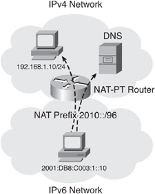
![]() NAT-PT uses a 96-bit IPv6 network prefix to direct all IPv6 traffic that needs to be translated to the NAT-PT router. This prefix can be any routable prefix within the IPv6 domain. IPv6 routing must be configured such that all IPv6 packets addressed to this prefix are routed to the NAT-PT device. When the NAT-PT router receives an IPv6 packet destined for the NAT-PT prefix, it translates the packet according to the configured mapping rules. This prefix is also used in the translation of IPv4 address into IPv6 addresses.
NAT-PT uses a 96-bit IPv6 network prefix to direct all IPv6 traffic that needs to be translated to the NAT-PT router. This prefix can be any routable prefix within the IPv6 domain. IPv6 routing must be configured such that all IPv6 packets addressed to this prefix are routed to the NAT-PT device. When the NAT-PT router receives an IPv6 packet destined for the NAT-PT prefix, it translates the packet according to the configured mapping rules. This prefix is also used in the translation of IPv4 address into IPv6 addresses.
![]() Within the IPv6 domain, external IPv4 addresses are mapped to IPv6 addresses. This mapping is done statically (by means of predefined mapping between IPv4 and IPv6 addresses using the NAT-PT IPv6 prefix) or dynamically (by appending the IPv4 address to the NAT-PT IPv6 prefix). Similarly, static and dynamic mapping can be configured for translating internal IPv6 addresses to external IPv4 addresses.
Within the IPv6 domain, external IPv4 addresses are mapped to IPv6 addresses. This mapping is done statically (by means of predefined mapping between IPv4 and IPv6 addresses using the NAT-PT IPv6 prefix) or dynamically (by appending the IPv4 address to the NAT-PT IPv6 prefix). Similarly, static and dynamic mapping can be configured for translating internal IPv6 addresses to external IPv4 addresses.
![]() Therefore, the NAT-PT router performs several bidirectional translations, including DNS, addressing, packet headers, and so forth.
Therefore, the NAT-PT router performs several bidirectional translations, including DNS, addressing, packet headers, and so forth.
![]() The next section examines static NAT-PT. The following section examines dynamic NAT-PT.
The next section examines static NAT-PT. The following section examines dynamic NAT-PT.
 Static NAT-PT for IPv6
![]() This section explores static NAT-PT.
This section explores static NAT-PT.
Static NAT-PT Operation
![]() Figure 8-57 illustrates how static NAT-PT operates. In this scenario, R4 and R2 need to communicate; R4 only has an IPv6 address and R2 only has an IPv4 address. Two static NAT-PT translations are configured on router R1 to allow bidirectional traffic between the two devices. Both the source and destination addresses in both directions will be translated.
Figure 8-57 illustrates how static NAT-PT operates. In this scenario, R4 and R2 need to communicate; R4 only has an IPv6 address and R2 only has an IPv4 address. Two static NAT-PT translations are configured on router R1 to allow bidirectional traffic between the two devices. Both the source and destination addresses in both directions will be translated.


![]() When R4 wants to communicate with R2, it sends an IPv6 packet (the only type it knows) with its own source address (14::4) and a destination address (1144::1) within the NAT-PT prefix. This prefix guides packets to the NAT-PT router, R1. The NAT-PT prefix is configured on R1 and typically advertised by R1 in an IGP such as RIPng or OSPFv3. The destination IPv6 address (1144::1) is the representation of the IPv4-only devices in the IPv6 world. When R1 receives the IPv6 packet from R4, it translates this destination IPv6 address to R2’s IPv4 address. This is one of the static translation entries configured on R1; it is an IPv4-to-IPv6 mapping that gives the IPv4-only device R2 an address in the IPv6 world.
When R4 wants to communicate with R2, it sends an IPv6 packet (the only type it knows) with its own source address (14::4) and a destination address (1144::1) within the NAT-PT prefix. This prefix guides packets to the NAT-PT router, R1. The NAT-PT prefix is configured on R1 and typically advertised by R1 in an IGP such as RIPng or OSPFv3. The destination IPv6 address (1144::1) is the representation of the IPv4-only devices in the IPv6 world. When R1 receives the IPv6 packet from R4, it translates this destination IPv6 address to R2’s IPv4 address. This is one of the static translation entries configured on R1; it is an IPv4-to-IPv6 mapping that gives the IPv4-only device R2 an address in the IPv6 world.
![]() When R1 receives the IPv6 packet from R4, it also translates R4’s IPv6 source address (14::4) to an IPv4 source address (172.16.123.100). This is the other static translation entry configured on R1; it is an IPv6-to-IPv4 mapping that gives the IPv6-only device R4 an address in the IPv4 world. The translated IPv4 address is typically within the destination IPv4 subnet; otherwise, it must be advertised to the IPv4 routers via static or dynamic routing.
When R1 receives the IPv6 packet from R4, it also translates R4’s IPv6 source address (14::4) to an IPv4 source address (172.16.123.100). This is the other static translation entry configured on R1; it is an IPv6-to-IPv4 mapping that gives the IPv6-only device R4 an address in the IPv4 world. The translated IPv4 address is typically within the destination IPv4 subnet; otherwise, it must be advertised to the IPv4 routers via static or dynamic routing.
![]() When R2 replies to R4, traffic travels in the other direction and R1 translates the IPv4 source address (172.16.123.2) to IPv6 (1144::1) the IPv4 destination address (172.16.123.100) to IPv6 (14::4) by using the configured translation entries.
When R2 replies to R4, traffic travels in the other direction and R1 translates the IPv4 source address (172.16.123.2) to IPv6 (1144::1) the IPv4 destination address (172.16.123.100) to IPv6 (14::4) by using the configured translation entries.
Static NAT-PT Configuration and Verification Commands
![]() The configuration and verification of static NAT-PT in this section use many of the commands explored earlier in this chapter. Other commands used in the upcoming examples are noted in this section.
The configuration and verification of static NAT-PT in this section use many of the commands explored earlier in this chapter. Other commands used in the upcoming examples are noted in this section.
![]() The ipv6 nat commands have similar syntax to the ip nat commands you are probably familiar with. However, as discussed, NAT-PT does more than translate addresses because it is translating between two different protocols.
The ipv6 nat commands have similar syntax to the ip nat commands you are probably familiar with. However, as discussed, NAT-PT does more than translate addresses because it is translating between two different protocols.
![]() The ipv6 nat interface configuration command designates that traffic originating from or destined for the interface is subject to NAT-PT.
The ipv6 nat interface configuration command designates that traffic originating from or destined for the interface is subject to NAT-PT.
![]() The ipv6 nat prefix ipv6-prefix/prefix-length global or interface configuration command assigns an IPv6 prefix where matching IPv6 packets will be translated using NAT-PT. The ipv6-prefix/prefix-length specifies the IPv6 network used as the NAT-PT prefix; it is important to note that the prefix-length must be 96.
The ipv6 nat prefix ipv6-prefix/prefix-length global or interface configuration command assigns an IPv6 prefix where matching IPv6 packets will be translated using NAT-PT. The ipv6-prefix/prefix-length specifies the IPv6 network used as the NAT-PT prefix; it is important to note that the prefix-length must be 96.
![]() The ipv6 nat v4v6 source ipv4-address ipv6-address global configuration command configures IPv4-to-IPv6 static address translation using NAT-PT. The ipv4-address ipv6-address parameters specify a single static translation. The IPv4 address is translated to the IPv6 address.
The ipv6 nat v4v6 source ipv4-address ipv6-address global configuration command configures IPv4-to-IPv6 static address translation using NAT-PT. The ipv4-address ipv6-address parameters specify a single static translation. The IPv4 address is translated to the IPv6 address.
![]() The ipv6 nat v6v4 source ipv6-address ipv4-address global configuration command configures IPv4-to-IPv6 static address translation using NAT-PT. The ipv6-address ipv4-address parameters specify a single static translation. The IPv6 address is translated to the IPv4 address.
The ipv6 nat v6v4 source ipv6-address ipv4-address global configuration command configures IPv4-to-IPv6 static address translation using NAT-PT. The ipv6-address ipv4-address parameters specify a single static translation. The IPv6 address is translated to the IPv4 address.
![]() The show ipv6 nat translations EXEC command displays active NAT-PT translations.
The show ipv6 nat translations EXEC command displays active NAT-PT translations.
Static NAT-PT Configuration and Verification Example
![]() Figure 8-58 illustrates a network used to demonstrate the configuration and verification of static NAT-PT. R3 and R4 are IPv6-only devices, and R2 is an IPv4-only device. R1 is the NAT-PT router. In this example, we require R4 and R2 to communicate. As described in the previous section, two static translation entries are required in R1 to allow this bidirectional communication.
Figure 8-58 illustrates a network used to demonstrate the configuration and verification of static NAT-PT. R3 and R4 are IPv6-only devices, and R2 is an IPv4-only device. R1 is the NAT-PT router. In this example, we require R4 and R2 to communicate. As described in the previous section, two static translation entries are required in R1 to allow this bidirectional communication.


![]() All NAT-PT configuration is done on one device, the NAT-PT router, which is R1 in this example. The other routers are used for testing and verification, but one of the benefits of this transition technique is that only a single device is configured.
All NAT-PT configuration is done on one device, the NAT-PT router, which is R1 in this example. The other routers are used for testing and verification, but one of the benefits of this transition technique is that only a single device is configured.
![]() Example 8-125 illustrates the NAT-PT configuration on R1. First, NAT-PT is enabled on the two interfaces on which it is required, the interfaces pointing to R2 and R4, with the ipv6 nat command. Notice that, unlike IPv4 NAT configurations, no inside or outside keywords are required, because having an IPv6-only side and an IPv4-only side resolves the issue of boundaries.
Example 8-125 illustrates the NAT-PT configuration on R1. First, NAT-PT is enabled on the two interfaces on which it is required, the interfaces pointing to R2 and R4, with the ipv6 nat command. Notice that, unlike IPv4 NAT configurations, no inside or outside keywords are required, because having an IPv6-only side and an IPv4-only side resolves the issue of boundaries.
R1(config-if)#ipv6 nat
R1(config-if)#
%LINEPROTO-5-UPDOWN: Line protocol on Interface NV10, changed state to up
R1(config-if)#interface s0/1/0
R1(config-if)#ipv6 nat
R1(config-if)#exit
R1(config)#ipv6 nat v6v4 ?
pool Configure a IPv4 address pool
source Source Address Translation
R1(config)#ipv6 nat v6v4 source ?
X:X:X:X::X IPv6 address to translate
list Specify access list
route-map Configure a route-map
R1(config)#ipv6 nat v6v4 source 14::4 172.16.123.100
R1(config)#ipv6 nat v4v6 source 172.16.123.2 1144::1
R1(config)#exit
R1#
R1#debug ipv6 routing
IPv6 routing table events debugging is on
R1#config t
Enter configuration commands, one per line. End with CNTL/Z.
R1(config)#ipv6 nat prefix 1144::/64
% Invalid prefix length
R1(config)#ipv6 nat prefix 1144::/32
% Invalid prefix length
R1(config)#ipv6 nat prefix 1144::/96
R1(config)#
IPv6RT[Default]: connected, Route add 1144::/96 [new]
IPv6RT[Default]: connected, Add 1144::/96 to table
IPv6RT[Default]: connected, Adding next-hop :: over NV10 for 1144::/96, [0/0]
IPv6RT[Default]: Event: 1144::/96, Add, owner connected, previous None
R1(config)#
![]() Next in Example 8-125, the ipv6 nat v6v4 source command is used to configure the mapping between R4’s IPv6 source address (14::4) and the IPv4 address that R4 appears as in the IPv4 world (172.16.123.100). Notice that 172.16.123.100 is a valid address on the subnet between R1 and R2. It is an unused IP address on the destination subnet, so R1 does not need to advertise a new subnet to R2. Traffic coming from R4 will therefore look like it is coming from this R1-R2 subnet.
Next in Example 8-125, the ipv6 nat v6v4 source command is used to configure the mapping between R4’s IPv6 source address (14::4) and the IPv4 address that R4 appears as in the IPv4 world (172.16.123.100). Notice that 172.16.123.100 is a valid address on the subnet between R1 and R2. It is an unused IP address on the destination subnet, so R1 does not need to advertise a new subnet to R2. Traffic coming from R4 will therefore look like it is coming from this R1-R2 subnet.
![]() Example 8-125 also shows the ipv6 nat v4v6 source command, used to configure the mapping for return traffic—between R2’s IPv4 source address (172.16.123.2) and the IPv6 address that R2 appears as in the IPv6 world (1144::1). This IPv6 address does not exist in the IPv6 world; it is an unused address selected to represent IPv4 devices in the IPv6 world. This IPv6 address is on the NAT-PT prefix, which is configured next.
Example 8-125 also shows the ipv6 nat v4v6 source command, used to configure the mapping for return traffic—between R2’s IPv4 source address (172.16.123.2) and the IPv6 address that R2 appears as in the IPv6 world (1144::1). This IPv6 address does not exist in the IPv6 world; it is an unused address selected to represent IPv4 devices in the IPv6 world. This IPv6 address is on the NAT-PT prefix, which is configured next.
![]() Before configuring the NAT-PT prefix in Example 8-125, the debug ipv6 routing command is entered so that the behavior of the router can be observed during the configuration. The ipv6 nat prefix command is entered, to define the NAT-PT prefix. Traffic destined to this prefix received on R1 will be translated. In this example, 1144::/64 is the NAT-PT prefix selected; it identifies all destinations on the IPv4-only network. As the example shows, you must configure a 96-bit prefix length. This is because 32-bit IPv4 addresses are translated into 128-bit IPv6 addresses; the difference is 128-32 = 96 bits, so this is the required number of bits in the prefix. Notice that this ipv6 nat prefix command creates a connected route in R1’s routing table.
Before configuring the NAT-PT prefix in Example 8-125, the debug ipv6 routing command is entered so that the behavior of the router can be observed during the configuration. The ipv6 nat prefix command is entered, to define the NAT-PT prefix. Traffic destined to this prefix received on R1 will be translated. In this example, 1144::/64 is the NAT-PT prefix selected; it identifies all destinations on the IPv4-only network. As the example shows, you must configure a 96-bit prefix length. This is because 32-bit IPv4 addresses are translated into 128-bit IPv6 addresses; the difference is 128-32 = 96 bits, so this is the required number of bits in the prefix. Notice that this ipv6 nat prefix command creates a connected route in R1’s routing table.
![]() Example 8-126 displays the output of the show ipv6 route connected command, confirming that the NAT-PT 96-bit prefix is there. Notice that this prefix is directly connected to the interface NVI0; NVI0 is a NAT virtual interface and exists to allow NAT traffic flows. (You may have noticed earlier in Example 8-125 that this interface NVI0 came up as soon as NAT-PT was enabled on the Serial 0/0/0 interface.) However, as also shown in the example, R4 does not yet know about this prefix (it is not in R4’s IPv6 routing table) and therefore cannot reach it. So, on R1, the redistribute connected command (with a seed metric of 3) is entered under the RIPng process. R4 now has a route to the 1144 prefix and can forward traffic to it.
Example 8-126 displays the output of the show ipv6 route connected command, confirming that the NAT-PT 96-bit prefix is there. Notice that this prefix is directly connected to the interface NVI0; NVI0 is a NAT virtual interface and exists to allow NAT traffic flows. (You may have noticed earlier in Example 8-125 that this interface NVI0 came up as soon as NAT-PT was enabled on the Serial 0/0/0 interface.) However, as also shown in the example, R4 does not yet know about this prefix (it is not in R4’s IPv6 routing table) and therefore cannot reach it. So, on R1, the redistribute connected command (with a seed metric of 3) is entered under the RIPng process. R4 now has a route to the 1144 prefix and can forward traffic to it.
IPv6 Routing Table – Default - 8 entries
Codes: C – Connected, L – Local, S – Static, U – Per-user Static route
M – MIPv6, R – RIP, I1 – ISIS L1, I2 – ISIS L2
IA – ISIS interarea, IS – ISIS summary, D – EIGRP, EX – EIGRP external
C 13::64 [0/0]
via FastEthernet0/0, directly connected
C 14::/64 [0/0]
via Serial0/0/0, directly connected
C 1144::/96 [0/0]
via NV10, directly connected
R1(config)#
R4#show ipv6 route | inc 1144
R4#
R1(config)#ipv6 router rip NAT-PT
R1(config-rtr)#redistribute connected metric 3
R1(config-rtr)#
R4#show ipv6 route | inc 1144
R 1144::/96 [120/4]
R4#
R4#show ipv6 route rip
IPv6 Routing Table – 12 entries
Codes: C – Connected, L – Local, S – Static, R – RIP, B – BGP
U – Per-user Static route
I1 – ISIS L1, I2 – ISIS L2, IA – ISIS interarea, IS – ISIS summary
O – OSPF intra, OI – OSPF inter, OE1 – OSPF ext 1, OE2 – OSPF ext 2
ON1 – OSPF NSSA ext 1, ON2 – OSPF NSSA ext 2
R 13::/64 [120/2]
via FE80::1, Serial 1/1.7
R 1144::/96 [120/4]
via FE80::1, Serial 1/1.7
R4#
![]() To test the configuration, a ping is sent from R4 to 1144::1, the IPv6 address representing R2. Example 8-127 shows that the ping is successful. The example also shows the IPv6 NAT table on R1, which includes the two static translation entries (172.16.123.100 to 14::4, and 172.16.123.2 to 1144::1) and the ICMPv6 entry created for the ping.
To test the configuration, a ping is sent from R4 to 1144::1, the IPv6 address representing R2. Example 8-127 shows that the ping is successful. The example also shows the IPv6 NAT table on R1, which includes the two static translation entries (172.16.123.100 to 14::4, and 172.16.123.2 to 1144::1) and the ICMPv6 entry created for the ping.
| Note |
|
R4#ping 1144::1
Type escape sequence to abort.
Sending 5, 100-byte ICMP Echos to 1144::1, timeout is 2 seconds:
!!!!!
Success rate is 100 percent (5/5), round-trip min/avg/max = 68/70/73 ms
R4#

R1#show ipv6 nat translations
Prot  IPv4 source               IPv6 source
     IPv4 destination          IPv6 destination
—-    —-                        —-
     172.16.123.2              1144::1
icmp  172.16.123.100,7364       14::4, 7364
     172.16.123.2, 7364        1144::1, 7364
—-    172.16.123.100            14::4
     —-                        —-
R1#
![]() As a final test, the debug ip icmp command is entered on R2, and the ping is reentered on R4. The results are shown in Example 8-128. In the R2 debug output, notice that the ping reply is being sent to the destination address 172.16.123.100, the IPv4 address representing R4 in the IPv4 world.
As a final test, the debug ip icmp command is entered on R2, and the ping is reentered on R4. The results are shown in Example 8-128. In the R2 debug output, notice that the ping reply is being sent to the destination address 172.16.123.100, the IPv4 address representing R4 in the IPv4 world.
R2#debug ip icmp
ICMP packet debugging is on
R2#


R4#ping 1144::1
Type escape sequence to abort.
Sending 5, 100-byte ICMP Echos to 1144::1, timeout is 2 seconds:
!!!!!
Success rate is 100 percent (5/5), round-trip min/avg/max = 68/70/73 ms
R4#


R2#
ICMP: echo reply sent, src 172.16.123.2, dst 172.16.123.100
ICMP: echo reply sent, src 172.16.123.2, dst 172.16.123.100
ICMP: echo reply sent, src 172.16.123.2, dst 172.16.123.100
ICMP: echo reply sent, src 172.16.123.2, dst 172.16.123.100
ICMP: echo reply sent, src 172.16.123.2, dst 172.16.123.100
![]() This example illustrated that static NAT-PT is quite simple to configure, but it requires planning the translated addresses in both domains. Static NAT-PT is not scalable; it would be very cumbersome to create static entries for multiple sources communicating with multiple destinations. The next section discusses a more scalable solution, dynamic NAT-PT.
This example illustrated that static NAT-PT is quite simple to configure, but it requires planning the translated addresses in both domains. Static NAT-PT is not scalable; it would be very cumbersome to create static entries for multiple sources communicating with multiple destinations. The next section discusses a more scalable solution, dynamic NAT-PT.
Dynamic NAT-PT for IPv6
![]() With dynamic NAT-PT, addresses are allocated from an address pool, the same as is done with IPv4 dynamic NAT. And again, the commands have similar syntax to their IPv4 NAT counterparts.
With dynamic NAT-PT, addresses are allocated from an address pool, the same as is done with IPv4 dynamic NAT. And again, the commands have similar syntax to their IPv4 NAT counterparts.
![]() With dynamic NAT-PT, the NAT-PT router receives, for example, a packet with an IPv6 destination address of an arbitrarily assigned 96-bit prefix (the NAT-PT prefix), the same as it did with static NAT-PT. This time though, instead of translating this to an IPv4 address that was statically configured, the NAT-PT router translates it to an IPv4 address from an address pool.
With dynamic NAT-PT, the NAT-PT router receives, for example, a packet with an IPv6 destination address of an arbitrarily assigned 96-bit prefix (the NAT-PT prefix), the same as it did with static NAT-PT. This time though, instead of translating this to an IPv4 address that was statically configured, the NAT-PT router translates it to an IPv4 address from an address pool.
Dynamic NAT-PT Configuration and Verification Commands
![]() The configuration and verification of dynamic NAT-PT in this section use many of the commands explored earlier in this chapter. Other commands used in the upcoming examples are noted in this section.
The configuration and verification of dynamic NAT-PT in this section use many of the commands explored earlier in this chapter. Other commands used in the upcoming examples are noted in this section.
![]() The ipv6 nat v4v6 source {list {access-list-number | name} pool name} global configuration command configures IPv4 to IPv6 dynamic address translation using NAT-PT. The parameters of this command are described in Table 8-16.
The ipv6 nat v4v6 source {list {access-list-number | name} pool name} global configuration command configures IPv4 to IPv6 dynamic address translation using NAT-PT. The parameters of this command are described in Table 8-16.
|
|
|
|---|---|
|
|
|
|
|
|
![]() The ipv6 nat v4v6 pool name start-ipv6 end-ipv6 prefix-length prefix-length defines a pool of IPv6 addresses for NAT-PT. The parameters of this command are described in Table 8-17.
The ipv6 nat v4v6 pool name start-ipv6 end-ipv6 prefix-length prefix-length defines a pool of IPv6 addresses for NAT-PT. The parameters of this command are described in Table 8-17.
|
|
|
|---|---|
|
|
|
|
|
|
|
|
|
![]() The ipv6 nat v6v4 source {list {access-list-name} pool name} global configuration command configures IPv6-to-IPv4 dynamic address translation using NAT-PT. The parameters of this command are described in Table 8-18.
The ipv6 nat v6v4 source {list {access-list-name} pool name} global configuration command configures IPv6-to-IPv4 dynamic address translation using NAT-PT. The parameters of this command are described in Table 8-18.
|
|
|
|---|---|
|
|
|
|
|
|
![]() The ipv6 nat v6v4 pool name start-ipv4 end-ipv4 prefix-length prefix-length defines a pool of IPv4 addresses for NAT-PT. The parameters of this command are described in Table 8-19.
The ipv6 nat v6v4 pool name start-ipv4 end-ipv4 prefix-length prefix-length defines a pool of IPv4 addresses for NAT-PT. The parameters of this command are described in Table 8-19.
|
| |
|---|---|
|
|
|
|
|
|
|
|
|
![]() The service finger global configuration command configures a system to accept Finger protocol requests. The Finger service allows remote users to view the output equivalent to the show users command. When this command is configured on a router, the router responds to a telnet address finger command from a remote host by immediately displaying the output of the show users command and then closing the connection.
The service finger global configuration command configures a system to accept Finger protocol requests. The Finger service allows remote users to view the output equivalent to the show users command. When this command is configured on a router, the router responds to a telnet address finger command from a remote host by immediately displaying the output of the show users command and then closing the connection.
| Note |
|
![]() The show ipv6 nat statistics EXEC command displays NAT-PT statistics.
The show ipv6 nat statistics EXEC command displays NAT-PT statistics.
![]() The debug ipv6 nat EXEC command displays debug messages for NAT-PT translation events.
The debug ipv6 nat EXEC command displays debug messages for NAT-PT translation events.
Dynamic NAT-PT Configuration and Verification Examples
![]() In this section two examples are presented. The first is for IPv6-to-IPv4 traffic flows, and the second is for IPv4-to-IPv6 traffic flows.
In this section two examples are presented. The first is for IPv6-to-IPv4 traffic flows, and the second is for IPv4-to-IPv6 traffic flows.
IPv6-to-IPv4 Dynamic NAT-PT Configuration and Verification Example
![]() Figure 8-59 illustrates a network used to demonstrate the configuration and verification of IPv6-to-IPv4 traffic flows with dynamic NAT-PT. This network is similar to the one used in the static NAT-PT example, with an additional connection between R1 and R2. R3 and R4 are IPv6-only devices, and R2 is an IPv4-only device. R1 is the NAT-PT router. The loopback interfaces on R3 and R4 are used in this example.
Figure 8-59 illustrates a network used to demonstrate the configuration and verification of IPv6-to-IPv4 traffic flows with dynamic NAT-PT. This network is similar to the one used in the static NAT-PT example, with an additional connection between R1 and R2. R3 and R4 are IPv6-only devices, and R2 is an IPv4-only device. R1 is the NAT-PT router. The loopback interfaces on R3 and R4 are used in this example.


![]() In this example, we want to dynamically translate traffic coming from the R3 and R4 loopback interface addresses to a pool of IPv4 addresses, and to dynamically translate traffic sourced from the R3 and R4 physical interfaces to be dynamically translated to a different pool of IPv4 addresses. R2’s two IPv4 interface addresses are destination addresses in this scenario and will be represented by (translated to) two different IPv6 addresses. This scenario simulates multiple IPv6 host devices being translated to different address pools as they communicate with multiple IPv4 hosts.
In this example, we want to dynamically translate traffic coming from the R3 and R4 loopback interface addresses to a pool of IPv4 addresses, and to dynamically translate traffic sourced from the R3 and R4 physical interfaces to be dynamically translated to a different pool of IPv4 addresses. R2’s two IPv4 interface addresses are destination addresses in this scenario and will be represented by (translated to) two different IPv6 addresses. This scenario simulates multiple IPv6 host devices being translated to different address pools as they communicate with multiple IPv4 hosts.
![]() Figure 8-60 displays the translations that will occur in this example. For traffic sourced from the R3 and R4 physical interfaces (13::3 and 14::4), a pool on the 172.16.123.0 subnet is used, specifically the 172.16.123.100 and 172.16.123.101 addresses. For traffic sourced from the R3 and R4 loopback interfaces (103::1 and 104::1), a pool on the 172.16.12.0 subnet is used, specifically the 172.16.12.100 and 172.16.12.101 addresses. The destination address 1144::1 represents R2’s 172.16.123.2 interface in the IPv6 world, and the destination address 1144::2 represents R2’s 172.16.12.2 interface in the IPv6 world.
Figure 8-60 displays the translations that will occur in this example. For traffic sourced from the R3 and R4 physical interfaces (13::3 and 14::4), a pool on the 172.16.123.0 subnet is used, specifically the 172.16.123.100 and 172.16.123.101 addresses. For traffic sourced from the R3 and R4 loopback interfaces (103::1 and 104::1), a pool on the 172.16.12.0 subnet is used, specifically the 172.16.12.100 and 172.16.12.101 addresses. The destination address 1144::1 represents R2’s 172.16.123.2 interface in the IPv6 world, and the destination address 1144::2 represents R2’s 172.16.12.2 interface in the IPv6 world.


![]() Example 8-129 illustrates the NAT-PT configuration on R1. First, NAT-PT is enabled on the four interfaces on which it is required, the interfaces pointing to R2, R3, and R4, with the ipv6 nat command. The example also shows the ipv6 nat v4v6 source commands, used to configure the static mappings for R2’s IPv4 source addresses (172.16.12.2 and 172.16.123.2) and the IPv6 addresses that R2 appears as in the IPv6 world (1144::1 and 1144::2). (These IPv6 address do not exist in the IPv6 world; they are on the NAT-PT prefix, which is configured near the end of Example 8-129.)
Example 8-129 illustrates the NAT-PT configuration on R1. First, NAT-PT is enabled on the four interfaces on which it is required, the interfaces pointing to R2, R3, and R4, with the ipv6 nat command. The example also shows the ipv6 nat v4v6 source commands, used to configure the static mappings for R2’s IPv4 source addresses (172.16.12.2 and 172.16.123.2) and the IPv6 addresses that R2 appears as in the IPv6 world (1144::1 and 1144::2). (These IPv6 address do not exist in the IPv6 world; they are on the NAT-PT prefix, which is configured near the end of Example 8-129.)
R1(config-if)#ipv6 nat
R1(config-if)#interface Serial0/0/0.2
R1(config-subif)#ipv6 nat
R1(config-subif)#interface Serial0/0/0.4
R1(config-subif)#ipv6 nat
R1(config-subif)#interface Serial0/1/0
R1(config-if)#ipv6 nat
R1(config-if)#ipv6 nat v4v6 source 172.16.12.2 1144::2
R1(config)#ipv6 nat v4v6 source 172.16.123.2 1144::1
R1(config)#
R1(config)#ipv6 nat v6v4 source list LOOPBACK pool POOL_12
R1(config)#ipv6 nat v6v4 source list PHYSICAL pool POOL_123
R1(config)#
R1(config)#ipv6 nat v6v4 pool POOL_12 172.16.12.100 172.16.12.101 prefix-length 24
R1(config)#ipv6 nat v6v4 pool POOL_123 172.16.123.100 172.16.123.101 prefix-length 24
R1(config)#
R1(config)#ipv6 access-list LOOPBACK
R1(config-ipv6-acl)#permit ipv6 104::/64 any
R1(config-ipv6-acl)#permit ipv6 103::/64 any
R1(config-ipv6-acl)#ipv6 access-list PHYSICAL
R1(config-ipv6-acl)#permit ipv6 13::/64 any
R1(config-ipv6-acl)#permit ipv6 14::/64 any
R1(config-ipv6-acl)#exit
R1(config)#
R1(config)#ipv6 nat prefix 1144::/96
R1(config)#ipv6 router rip NAT-PT
R1(config-rtr)#redistribute connected metric 1
R1(config-rtr)#exit
R1(config)#
![]() Next in Example 8-129, the ipv6 nat v6v4 source commands are used to configure the dynamic mapping between the IPv6 addresses on R3 and R4 and the IPv4 addresses that R3 and R4 appear as in the IPv4 world. The first command uses the IPv6 access list LOOPBACK to identify the R3 and R4 loopback interface IPv6 addresses, and an address pool POOL_12 to define the IPv4 translated addresses. The second command uses an IPv6 access list called PHYSICAL to identify the R3 and R4 physical interface IPv6 addresses, and an address pool POOL_123 to define the IPv4 translated addresses in a different pool.
Next in Example 8-129, the ipv6 nat v6v4 source commands are used to configure the dynamic mapping between the IPv6 addresses on R3 and R4 and the IPv4 addresses that R3 and R4 appear as in the IPv4 world. The first command uses the IPv6 access list LOOPBACK to identify the R3 and R4 loopback interface IPv6 addresses, and an address pool POOL_12 to define the IPv4 translated addresses. The second command uses an IPv6 access list called PHYSICAL to identify the R3 and R4 physical interface IPv6 addresses, and an address pool POOL_123 to define the IPv4 translated addresses in a different pool.
![]() Next in Example 8-129 the IPv4 address pools are created. POOL_12 defines the addresses on the 172.16.12.0 subnet, and POOL_123 defines the addresses on the 172.16.123.0 subnet. The addresses chosen to be the translated addresses must, of course, be unused addresses in the IPv4 network.
Next in Example 8-129 the IPv4 address pools are created. POOL_12 defines the addresses on the 172.16.12.0 subnet, and POOL_123 defines the addresses on the 172.16.123.0 subnet. The addresses chosen to be the translated addresses must, of course, be unused addresses in the IPv4 network.
![]() Next in Example 8-129, the IPv6 access lists referenced in the earlier statements are created. The LOOPBACK access list permits the R3 and R4 loopback interface addresses, and the PHYSICAL access list permits the R3 and R4 physical interface addresses.
Next in Example 8-129, the IPv6 access lists referenced in the earlier statements are created. The LOOPBACK access list permits the R3 and R4 loopback interface addresses, and the PHYSICAL access list permits the R3 and R4 physical interface addresses.
![]() Finally in Example 8-129, the IPv6 NAT prefix is defined, and connected routes (including this prefix) are redistributed into RIPng (with a seed metric of 1).
Finally in Example 8-129, the IPv6 NAT prefix is defined, and connected routes (including this prefix) are redistributed into RIPng (with a seed metric of 1).
![]() Before conducting the verification tests, the service finger command is entered on R2, as shown in Example 8-130. (When this command is configured, and another device uses the telnet address finger command to connect to R2, R2 displays the output of the show users command and then closes the connection. The output displays the source IP address of the connecting device, which confirms that the NAT-PT configuration is working correctly.) On R1, the debug ipv6 nat command is entered, and then four Telnet tests are conducted from each of R3 and R4: from each router R3 and R4, a Telnet to each of R2’s addresses is performed, from both the router’s physical and loopback interfaces.
Before conducting the verification tests, the service finger command is entered on R2, as shown in Example 8-130. (When this command is configured, and another device uses the telnet address finger command to connect to R2, R2 displays the output of the show users command and then closes the connection. The output displays the source IP address of the connecting device, which confirms that the NAT-PT configuration is working correctly.) On R1, the debug ipv6 nat command is entered, and then four Telnet tests are conducted from each of R3 and R4: from each router R3 and R4, a Telnet to each of R2’s addresses is performed, from both the router’s physical and loopback interfaces.
![]() Example 8-130 includes the first 2 tests, and the resulting debug output on R1. The first Telnet is from R4’s physical interface (the default). The output confirms that this Telnet has a source address 172.16.123.101 in the IPv4 world. The second Telnet is from R4’s loopback interface. The output confirms that this Telnet has a source address 172.16.12.101 in the IPv4 world. Both are as expected. The first line of the debug output confirms that R4’s physical interface (14::4) source address is being translated to 172.16.123.101, and that 1144::1 is being translated to 172.16.123.2, R2’s address. The tenth line of the debug output confirms that R4’s loopback interface (104::1) source address is being translated to 172.16.12.100, and that 1144::1 is again being translated to 172.16.123.2, R2’s address. Notice that both source and destination addresses are being translated, and that both translations are occurring at the same time.
Example 8-130 includes the first 2 tests, and the resulting debug output on R1. The first Telnet is from R4’s physical interface (the default). The output confirms that this Telnet has a source address 172.16.123.101 in the IPv4 world. The second Telnet is from R4’s loopback interface. The output confirms that this Telnet has a source address 172.16.12.101 in the IPv4 world. Both are as expected. The first line of the debug output confirms that R4’s physical interface (14::4) source address is being translated to 172.16.123.101, and that 1144::1 is being translated to 172.16.123.2, R2’s address. The tenth line of the debug output confirms that R4’s loopback interface (104::1) source address is being translated to 172.16.12.100, and that 1144::1 is again being translated to 172.16.123.2, R2’s address. Notice that both source and destination addresses are being translated, and that both translations are occurring at the same time.
R2(config)#service finger
R2(config)#


R1(config)#do debug ipv6 nat
    IPv6 NAT-PT debugging is on
R1(config)#


R4#telnet 1144::1 finger
Trying 1144::1, 79 ... Open
   Line          User          Host(s)               Idle               Location
  0 con 0                        idle                     00:01:19
*194 vty 0                        idle                     00:00:00      172.16.123.101
 Interface       User                     Mode       Idle               Peer Address
[Connection to 1144::1 closed by foreign host]
R4#
R4#telnet 1144::1 finger /source-interface loopback 104
Trying 1144::1, 79 ... Open
   Line          User          Host(s)               Idle               Location
  0 con 0                        idle                     00:01:48
*194 vty 0                        idle                     00:00:00      172.16.12.100
 Interface       User                     Mode       Idle               Peer Address
[Connection to 1144::1 closed by foreign host]
R4#


R1(config)#
IPv6 NAT: IPv6->IPv4: tcp src (14::4) -> (172.16.123.101), dst (1144::1) ->
(172.16.123.2)
IPv6 NAT: IPv4->IPv6:  src (172.16.123.2) -> (1144::1), dst (172.16.123.101) ->
(14::4)
IPv6 NAT: IPv6->IPv4: tcp src (14::4) -> (172.16.123.101), dst (1144::1) ->
(172.16.123.2)
IPv6 NAT: IPv6->IPv4: tcp src (14::4) -> (172.16.123.101), dst (1144::1) ->
(172.16.123.2)
IPv6 NAT: IPv4->IPv6:  src (172.16.123.2) -> (1144::1), dst (172.16.123.101) ->
(14::4)
IPv6 NAT: IPv4->IPv6:  src (172.16.123.2) -> (1144::1), dst (172.16.123.101) ->
(14::4)
IPv6 NAT: IPv6->IPv4: tcp src (14::4) -> (172.16.123.101), dst (1144::1) ->
(172.16.123.2)
IPv6 NAT: IPv6->IPv4: tcp src (14::4) -> (172.16.123.101), dst (1144::1) ->
(172.16.123.2)
IPv6 NAT: IPv4->IPv6:  src (172.16.123.2) -> (1144::1), dst (172.16.123.101) ->
(14::4)
IPv6 NAT: IPv6->IPv4: tcp src (104::1) -> (172.16.12.100), dst (1144::1) ->
(172.16.123.2)
IPv6 NAT: IPv4->IPv6:  src (172.16.123.2) -> (1144::1), dst (172.16.12.100) ->
(104::1)
IPv6 NAT: IPv6->IPv4: tcp src (104::1) -> (172.16.12.100), dst (1144::1) ->
(172.16.123.2)
IPv6 NAT: IPv6->IPv4: tcp src (104::1) -> (172.16.12.100), dst (1144::1) ->
(172.16.123.2)
IPv6 NAT: IPv4->IPv6:  src (172.16.123.2) -> (1144::1), dst (172.16.12.100) ->
(104::1)
IPv6 NAT: IPv4->IPv6:  src (172.16.123.2) -> (1144::1), dst (172.16.12.100) ->
(104::1)
IPv6 NAT: IPv6->IPv4: tcp src (104::1) -> (172.16.12.100), dst (1144::1) ->
(172.16.123.2)
IPv6 NAT: IPv6->IPv4: tcp src (104::1) -> (172.16.12.100), dst (1144::1) ->
(172.16.123.2)
IPv6 NAT: IPv4->IPv6:  src (172.16.123.2) -> (1144::1), dst (172.16.12.100) ->
(104::1)
![]() Example 8-131 displays the final two Telnet tests from R4, with similar results. The first one is to R2’s second address from R4’s physical address, and the second one is to R2’s second address from R4’s loopback address.
Example 8-131 displays the final two Telnet tests from R4, with similar results. The first one is to R2’s second address from R4’s physical address, and the second one is to R2’s second address from R4’s loopback address.
Trying 1144::2, 79 ... Open
Line User Host(s) Idle Location
0 con 0 idle 00:06:53
*194 vty 0 idle 00:00:00 172.16.123.101
Interface User Mode Idle Peer Address
[Connection to 1144::2 closed by foreign host]
R4#
R4#telnet 1144::2 finger /source-interface loopback 104
Trying 1144::2, 79 ... Open
Line User Host(s) Idle Location
0 con 0 idle 00:07:11
*194 vty 0 idle 00:00:00 172.16.12.100
Interface User Mode Idle Peer Address
[Connection to 1144::2 closed by foreign host]
R4#
![]() Example 8-132 displays the four Telnet tests from R3, with similar results. The first test is to R2’s first address from R3’s physical address. The second test is to R2’s second address from R3’s physical address. The third test is to R2’s first address from R3’s loopback address. The final test is to R2’s second address from R3’s loopback address. All are successful and indicate an appropriate source address was selected.
Example 8-132 displays the four Telnet tests from R3, with similar results. The first test is to R2’s first address from R3’s physical address. The second test is to R2’s second address from R3’s physical address. The third test is to R2’s first address from R3’s loopback address. The final test is to R2’s second address from R3’s loopback address. All are successful and indicate an appropriate source address was selected.
Trying 1144::1, 79 ... Open
Line User Host(s) Idle Location
0 con 0 idle 00:07:58
*194 vty 0 idle 00:00:00 172.16.123.100
Interface User Mode Idle Peer Address
[Connection to 1144::1 closed by foreign host]
R3#telnet 1144::2 finger
Trying 1144::2, 79 ... Open
Line User Host(s) Idle Location
0 con 0 idle 00:08:12
*194 vty 0 idle 00:00:00 172.16.123.100
Interface User Mode Idle Peer Address
[Connection to 1144::2 closed by foreign host]
R3#
R3#telnet 1144::1 finger /source-interface loopback 103
Trying 1144::2, 79 ... Open
Line User Host(s) Idle Location
0 con 0 idle 00:09:52
*194 vty 0 idle 00:00:00 172.16.12.101
Interface User Mode Idle Peer Address
[Connection to 1144::1 closed by foreign host]
R3#
R3#telnet 1144::2 finger /source-interface loopback 103
Trying 1144::2, 79 ... Open
Line User Host(s) Idle Location
0 con 0 idle 00:10:05
*194 vty 0 idle 00:00:00 172.16.12.101
Interface User Mode Idle Peer Address
[Connection to 1144::2 closed by foreign host]
R3#
IPv4-to-IPv6 Dynamic NAT-PT Configuration and Verification Example
![]() This second example uses the same network as in Figure 8-59. In this scenario, however, IPv4 hosts are accessing IPv6 hosts. The traffic flows are sourced from R2’s physical interfaces (in the IPv4 world) and destined to R3’s physical interface (in the IPv6 world).
This second example uses the same network as in Figure 8-59. In this scenario, however, IPv4 hosts are accessing IPv6 hosts. The traffic flows are sourced from R2’s physical interfaces (in the IPv4 world) and destined to R3’s physical interface (in the IPv6 world).
![]() Figure 8-61 displays the translations that will occur in this example. For traffic sourced from R2’s physical interfaces (172.16.12.2 and 172.16.123.2), a pool of 1133::1 to 1133::2 is used. R3’s physical interface address (13::3) is seen in the IPv4-only world as 172.16.101.100.
Figure 8-61 displays the translations that will occur in this example. For traffic sourced from R2’s physical interfaces (172.16.12.2 and 172.16.123.2), a pool of 1133::1 to 1133::2 is used. R3’s physical interface address (13::3) is seen in the IPv4-only world as 172.16.101.100.


![]() IPv6 NAT-PT support is already configured on all four interfaces of router R1. This is confirmed in the show ipv6 nat statistics command output displayed in Example 8-133. Notice that all four of R1’s physical interfaces are running NAT-PT, as is the NVI0 interface.
IPv6 NAT-PT support is already configured on all four interfaces of router R1. This is confirmed in the show ipv6 nat statistics command output displayed in Example 8-133. Notice that all four of R1’s physical interfaces are running NAT-PT, as is the NVI0 interface.
Total active translations: 0 (0 static, 0 dynamic; 0 extended)
NAT-PT interfaces:
FastEthernet0/0, Serial0/0/0.2, Serial0/0/0.4, Serial0/1/0, NVI0
Hits: 0 Misses: 0
Expired translations: 10
R1#
![]() In the IPv6 world, the ipv6 nat prefix command defines the prefix that forces traffic to the NAT-PT router. There is no equivalent command in the IPv4 world, so additional configuration is required. R3’s physical interface address will be translated to an address on the 172.16.101.0 subnet. R1 therefore needs to advertise this subnet to R2. However, R1 must have an interface with an address in a subnet before it will advertise that subnet. Therefore, as shown in Example 8-134, a loopback interface is created on R1, and it is given an address in this subnet. On R1 and R2, an IPv4 RIP process is created to advertise the 172.16.0.0 network. The example confirms that R2 sees the 172.16.101.0 subnet. In fact, it has two equal-cost routes to it. R2 is therefore able to access the subnet on which R3 will appear to reside in the IPv4 world.
In the IPv6 world, the ipv6 nat prefix command defines the prefix that forces traffic to the NAT-PT router. There is no equivalent command in the IPv4 world, so additional configuration is required. R3’s physical interface address will be translated to an address on the 172.16.101.0 subnet. R1 therefore needs to advertise this subnet to R2. However, R1 must have an interface with an address in a subnet before it will advertise that subnet. Therefore, as shown in Example 8-134, a loopback interface is created on R1, and it is given an address in this subnet. On R1 and R2, an IPv4 RIP process is created to advertise the 172.16.0.0 network. The example confirms that R2 sees the 172.16.101.0 subnet. In fact, it has two equal-cost routes to it. R2 is therefore able to access the subnet on which R3 will appear to reside in the IPv4 world.
R1(config-if)#
%LINK-3-UPDOWN: Interface Loopback101, changed state to up
%LINEPROTO-5-UPDOWN: Line protocol on Interface Loopback101, changed state to up
R1(config-if)#ip address 172.16.101.1 255.255.255.0
R1(config-if)#exit
R1(config)#
R1(config)#router rip
R1(config-router)#network 172.16.0.0
R1(config-router)#
R2(config)#router rip
R2(config-router)#network 172.16.0.0
R2(config-router)#do show ip route
Codes: C – connected, S – static, R – RIP, M – mobile, B – BGP
D – EIGRP, EX – EIGRP external, O – OSPF, IA – OSPF inter area
N1 – OSPF NSSA external type 1, N2 – OSPF NSSA external type 2
E1 – OSPF external type 1, E2 – OSPF external type 2
i – IS-IS, SU – IS-IS summary, L1 – IS-IS level-1, L2 – IS-IS level-2
ia – IS-IS inter area, * - candidate default, U – per-user static route
o – ODR, P – periodic downloaded static route
Gateway of last resort is not set
172.16.0.0/24 is subnetted, 3 subnets
C 172.16.12.0 is directly connected, Serial0/0/0
C 172.16.123.0 is directly connected, Serial0/1/0
R 172.16.101.0 [120/1] via 172.16.123.1, 00:00:07, Serial0/1/0
[120/1] via 172.16.12.1, 00:00:01, Serial0/0/0
R2(config-router)#
![]() Example 8-135 illustrates the NAT-PT configuration on R1. First, the ipv6 nat v6v4 source command configures the static mapping between R3’s physical interface (13::3) and the 172.16.101.100 address that R3 appears as in the IPv4 world. Next the ipv6 nat v4v6 source list command is used to configure the dynamic mapping for R2’s IPv4 source addresses (172.16.12.2 and 172.16.123.2) and the IPv6 addresses that R2 appears as in the IPv6 world (1144::1 and 1144::2). The command uses the access list IPV4 to identify the R2 interface IPv4 addresses, and an address pool POOL_1144 to define the IPv6 translated addresses. These translated IPv6 address do not exist in the IPv6 world; they are on the NAT-PT prefix, which is configured next. Finally, connected routes (including this prefix) are redistributed into RIPng (with a seed metric of 1).
Example 8-135 illustrates the NAT-PT configuration on R1. First, the ipv6 nat v6v4 source command configures the static mapping between R3’s physical interface (13::3) and the 172.16.101.100 address that R3 appears as in the IPv4 world. Next the ipv6 nat v4v6 source list command is used to configure the dynamic mapping for R2’s IPv4 source addresses (172.16.12.2 and 172.16.123.2) and the IPv6 addresses that R2 appears as in the IPv6 world (1144::1 and 1144::2). The command uses the access list IPV4 to identify the R2 interface IPv4 addresses, and an address pool POOL_1144 to define the IPv6 translated addresses. These translated IPv6 address do not exist in the IPv6 world; they are on the NAT-PT prefix, which is configured next. Finally, connected routes (including this prefix) are redistributed into RIPng (with a seed metric of 1).
R1(config)#ipv6 nat v4v6 source list IPV4 pool POOL_1144
R1(config)#ipv6 nat v4v6 pool POOL_1144 1144::1 1144::2 prefix-length 96
R1(config)#ip access-list standard IPV4
R1(config-std-nacl)#permit 172.16.123.0 0.0.0.255
R1(config-std-nacl)#permit 172.16.12.0 0.0.0.255
R1(config-std-nacl)#ipv6 nat prefix 1144::/96
R1(config)#ipv6 router rip NAT-PT
R1(config-rtr)#redistribute connected metric 1
R1(config-rtr)#
![]() Example 8-136 shows the output of the show ipv6 route rip command on R3, confirming that is has the 1144::/96 prefix in its routing table. Also shown are the IPv6 NAT-PT statistics and translations on R1. Notice that there is one static entry in the table, but no dynamic entries yet because no traffic has been sent.
Example 8-136 shows the output of the show ipv6 route rip command on R3, confirming that is has the 1144::/96 prefix in its routing table. Also shown are the IPv6 NAT-PT statistics and translations on R1. Notice that there is one static entry in the table, but no dynamic entries yet because no traffic has been sent.
IPv6 Routing Table – 10 entries
Codes: C – Connected, L – Local, S – Static, R – RIP, B – BGP
U – Per-user Static route
I1 – ISIS L1, I2 – ISIS L2, IA – ISIS interarea, IS – ISIS summary
O – OSPF intra, OI – OSPF inter, OE1 – OSPF ext 1, OE2 – OSPF ext 2
ON1 – OSPF NSSA ext 1, ON2 – OSPF NSSA ext 2
R 14::/64 [120/2]
via FE80::1, FastEthernet0/0
R 104::/64 [120/3]
via FE80::1, FastEthernet0/0
R 1144::/96 [120/2]
via FE80::1, FastEthernet0/0
R3#
R1(config-rtr)#do show ipv6 nat statistics
Total active translations: 1 (1 static, 0 dynamic; 0 extended)
NAT-PT interfaces:
FastEthernet0/0, Serial0/0/0.2, Serial0/0/0.4, Serial0/1/0, NVI0
Hits: 0 Misses: 0
Expired translations: 10
R1(config-rtr)#do show ipv6 nat translations
Prot IPv4 source IPv6 source
IPv4 destination IPv6 destination
—- 172.16.101.100 13::3
—- —-
R1(config-rtr)#
![]() The service finger command was previously entered on R3. Using a similar set of verification tests to those used in the previous example, debug ipv6 nat is enabled on R1 and some Telnets are performed from R2. The results are shown in Example 8-137. The first Telnet is from R2’s Serial 0/1/0 address to R3’s IPv4 world address. The second Telnet is from R2’s Serial 0/0/0 address to R3’s IPv4 world address. The output confirms that R2’s addresses are being translated to 1144::1 and 1144::2, as expected. The first line of the debug output confirms that R2’s physical interface (172.16.123.2) source address is being translated to 1144::1, and that 172.16.101.100 is being translated to 13::3, R3’s address. The tenth line of the debug output confirms that R2’s other physical interface (172.16.12.2) source address is being translated to 1144::2, and that 172.16.101.100 is again being translated to 13::3, R3’s address. Notice again that both source and destination addresses are being translated, and that both translations are occurring at the same time.
The service finger command was previously entered on R3. Using a similar set of verification tests to those used in the previous example, debug ipv6 nat is enabled on R1 and some Telnets are performed from R2. The results are shown in Example 8-137. The first Telnet is from R2’s Serial 0/1/0 address to R3’s IPv4 world address. The second Telnet is from R2’s Serial 0/0/0 address to R3’s IPv4 world address. The output confirms that R2’s addresses are being translated to 1144::1 and 1144::2, as expected. The first line of the debug output confirms that R2’s physical interface (172.16.123.2) source address is being translated to 1144::1, and that 172.16.101.100 is being translated to 13::3, R3’s address. The tenth line of the debug output confirms that R2’s other physical interface (172.16.12.2) source address is being translated to 1144::2, and that 172.16.101.100 is again being translated to 13::3, R3’s address. Notice again that both source and destination addresses are being translated, and that both translations are occurring at the same time.
R1#debug ipv6 nat
    IPv6 NAT-PT debugging is on
R1#


R2#telnet 172.16.101.100 finger /source-interface s0/1/0
Trying 172.16.101.100, 79 ... Open
   Line          User          Host(s)               Idle               Location
  0 con 0                        idle                     00:11:05
*194 vty 0                        idle                     00:00:00      1144::1
 Interface       User                     Mode       Idle               Peer Address
[Connection to 172.16.101.100 closed by foreign host]
R2#
R2#telnet 172.16.101.100 finger /source-interface s0/0/0
Trying 172.16.101.100, ... Open
   Line          User          Host(s)               Idle               Location
  0 con 0                        idle                     00:11:18
*194 vty 0                        idle                     00:00:00      1144::2
 Interface       User                     Mode       Idle               Peer Address
[Connection to 172.16.101.100 closed by foreign host]
R2#


R1#
IPv6 NAT: IPv4->IPv6:  src (172.16.123.2) -> (1144::1), dst (172.16.101.100) -> (13::3)
IPv6 NAT: IPv6->IPv4: tcp src (13::3) -> (172.16.101.100), dst (1144::1) -> (172.16.123.2)
IPv6 NAT: IPv4->IPv6:  src (172.16.123.2) -> (1144::1), dst (172.16.101.100) -> (13::3)
IPv6 NAT: IPv6->IPv4: tcp src (13::3) -> (172.16.101.100), dst (1144::1) -> (172.16.123.2)
IPv6 NAT: IPv4->IPv6:  src (172.16.123.2) -> (1144::1), dst (172.16.101.100) -> (13::3)
IPv6 NAT: IPv6->IPv4: tcp src (13::3) -> (172.16.101.100), dst (1144::1) -> (172.16.123.2)
IPv6 NAT: IPv4->IPv6:  src (172.16.123.2) -> (1144::1), dst (172.16.101.100) -> (13::3)
IPv6 NAT: IPv4->IPv6:  src (172.16.123.2) -> (1144::1), dst (172.16.101.100) -> (13::3)
IPv6 NAT: IPv6->IPv4: tcp src (13::3) -> (172.16.101.100), dst (1144::1) -> (172.16.123.2)
IPv6 NAT: IPv4->IPv6:  src (172.16.12.2) -> (1144::2), dst (172.16.101.100) -> (13::3)
IPv6 NAT: IPv6->IPv4: tcp src (13::3) -> (172.16.101.100), dst (1144::2) -> (172.16.12.2)
IPv6 NAT: IPv4->IPv6:  src (172.16.12.2) -> (1144::2), dst (172.16.101.100) -> (13::3)
IPv6 NAT: IPv6->IPv4: tcp src (13::3) -> (172.16.101.100), dst (1144::2) -> (172.16.12.2)
IPv6 NAT: IPv4->IPv6:  src (172.16.12.2) -> (1144::2), dst (172.16.101.100) -> (13::3)
IPv6 NAT: IPv6->IPv4: tcp src (13::3) -> (172.16.101.100), dst (1144::2) -> (172.16.12.2)
IPv6 NAT: IPv4->IPv6:  src (172.16.12.2) -> (1144::2), dst (172.16.101.100) -> (13::3)
IPv6 NAT: IPv4->IPv6:  src (172.16.12.2) -> (1144::2), dst (172.16.101.100) -> (13::3)
![]() Example 8-138 again examines the NAT-PT translation table on R1. This time the static translation is the last entry. There are two other dynamic entries because of the Telnet testing.
Example 8-138 again examines the NAT-PT translation table on R1. This time the static translation is the last entry. There are two other dynamic entries because of the Telnet testing.
Summary
![]() In this chapter, you learned about IPv6. The chapter focused on the following topics:
In this chapter, you learned about IPv6. The chapter focused on the following topics:
- The issues associated with IPv4, including address depletion, Internet routing table expansion, and the lack of a true end-to-end model.
- The features of IPv6, including larger address space, elimination of NAT and broadcast addresses, simplified header for improved router efficiency, support for mobility and security, and transition richness.
- The features of IPv6 addresses, including stateless autoconfiguration, prefix renumbering, multiple addresses per interface, link-local addresses, and the ability to use provider-dependent or provider-independent addressing.
- The 40-octet IPv6 header, with its 8 fields plus extension headers to handle options.
- The 128-bit IPv6 addresses written in the format is x:x:x:x:x:x:x:x, where x is a 16-bit hexadecimal field; each x is therefore four hexadecimal digits. The two ways to shorten the written form of IPv6 addresses are leading 0s within each set of four hexadecimal digits can be omitted and a pair of colons (::) can be used, once within an address, to represent any number (“a bunch”) of successive 0s.
- The IPv6 address interface ID. For Ethernet, it is based on the MAC address of the interface and is in an EUI-64 format. It is formed by inserting the hexadecimal number FFFE between the upper three bytes (the OUI field) and the lower 3 bytes (the vendor code or serial number field) of the MAC address, and setting the seventh bit in the high-order byte to 1 to indicate the uniqueness of the interface ID.
- The IPv6 address types—unicast (including global, link-local, and the deprecated site-local), multicast (for one to many), and anycast (for one to nearest). There are no broadcast addresses.
- The global unicast address that typically consists of a 48-bit global routing prefix, a 16-bit subnet ID, and a 64-bit interface ID (typically in EUI-64 bit format).
- Link-local addresses, that have a scope limited to the local link and are dynamically created on all IPv6 interfaces by using a specific link-local prefix FE80::/10 and a 64-bit interface identifier.
- The deprecated site-local addresses, that were in the FEC0::/10 range.
- IPv6 multicast addresses, defined by the prefix FF00::/8. The second octet of the address contains the prefix and transient (lifetime) flags, and the scope of the multicast address. Reserved multicast addresses include—FF02::1 (“all nodes” on a link, link-local scope); FF02::2 (“all routers” on a link); FF02::9 (“all RIPng routers” on a link). And FF02::1:FFXX:XXXX (solicited-node multicast on a link)
- IPv6 anycast addresses, allocated from the unicast address space and having the same format as unicast addresses. On a Cisco router, an IPv6 address becomes an anycast address when the anycast keyword is added to the end of the ipv6 address command.
- The ability to summarize IPv6 addresses, similar to IPv4 address summarization.
- IPv6 address configuration and verification commands:
- ipv6 unicast-routing global configuration command to enable the forwarding of IPv6 unicast datagrams.
- ipv6 cef global configuration command to enable CEFv6.
- ipv6 address address/prefix-length [eui-64 | link-local] interface configuration command to configure an IPv6 address for an interface and enable IPv6 processing on the interface. (Using a manually configured interface ID makes it much easier to remember, and therefore use, the link-local address.)
- ipv6 address autoconfig [default] interface configuration command to enable automatic configuration of IPv6 addresses using stateless autoconfiguration on an interface, and enable IPv6 processing on the interface.
- ipv6 unnumbered interface-type interface-number interface configuration command to enable IPv6 processing on an interface without assigning an explicit IPv6 address to the interface.
- ipv6 nd reachable-time milliseconds interface configuration command to specify the number of milliseconds that a remote IPv6 node is considered reachable.
- ipv6 neighbor ipv6-address interface-type interface-number hardware-address global configuration command to statically configure an entry in the IPv6 neighbor discovery cache, mapping the IPv6 address to the hardware address on an interface.
- show ipv6 interface [brief] [type number] [prefix] EXEC command to display the usability and status of interfaces configured for IPv6.
- show ipv6 routers [interface-type interface-number] [conflicts] EXEC command to display IPv6 router advertisement information received from onlink routers (those locally reachable on the link).
- show ipv6 neighbors [interface-type interface-number | ipv6-address | ipv6-hostname | statistics] EXEC command to display IPv6 ND cache information.
- debug ipv6 nd EXEC command to display messages associated with ICMPv6 neighbor discovery.
- debug ipv6 packet [access-list access-list-name] [detail] EXEC command to display information associated with IPv6 packet processing.
-
- The neighbor discovery or solicitation phase, similar to IPv4’s ARP: It allows an IPv6 router to determine the link-layer address of neighbors on the same link, to find neighbor routers, and to keep track of those neighbors for stateless autoconfiguration.
- Stateless autoconfiguration: When IPv6 is enabled on a router, it sends RAs (to advertise autoconfiguration parameters including the IPv6 prefix on the link), creates link-local addresses, and joins FF02::1 (all hosts) and FF02::2 (all routers) multicast groups on its interfaces.A host without an address sends out an RS. A router sends an RA with a prefix, and the host creates its address from the prefix.A host statically configured with an address sends an NS for that address.A host sends an NS for its own address for DAD. If unique, the host sends an NA for the address.Stateless autoconfiguration can also be used for renumbering.
- For a router to perform stateless autoconfiguration for other devices, it must have the ipv6 unicast-routing command. Routers configured with this command generate ICMPv6 RA messages. They do not generate RS messages. Routers configured with the ipv6 address auto-config command, and not configured with the ipv6 unicast-routing command, generate RS messages only. They do not generate RA messages. Devices keep their autoconfigured address for its lifetime if the interface stays up.
- The processes used to connect IPv6 devices on:
- Broadcast multiaccess connections: Uses the ICMPv6 ND process (NS and NA messages); can create a static mapping instead between an IPv6 unicast address and a MAC address with the ipv6 neighbor command.
- Point-to-point connections: Same process as broadcast multiaccess, using MAC address from a LAN interface to create the interface ID for link-local and global unicast addresses (unless manually configured).
- Point-to-multipoint connections over Frame Relay: Requires mapping between IPv6 addresses (link-local and global unicast) and DLCIs. Link-local mapping and broadcast support on the Frame Relay network is required for routing protocol support.
-
- The routing protocols available for IPv6, including RIPng, OSPFv3, IS-IS for IPv6, EIGRP for IPv6, and MBGP.
- The types of static routes that can be configured (directly attached, recursive, fully specified, and floating).
- Static route configuration and verification commands:
- ipv6 route ipv6-prefix/prefix-length {ipv6-address | interface-type interface-number [ipv6-address]} [administrative-distance] [administrative-multicast-distance | unicast | multicast] [next-hop-address] [tag tag] global configuration command configures a static route
- show ipv6 route [ipv6-address | ipv6-prefix/prefix-length | protocol | interface-type interface-number] EXEC command displays the current contents of the IPv6 routing table
-
- RIPng features: Based on RIPv2, distance vector, maximum of 15 hops, uses link-local addresses as source addresses, uses multicast address FF02::9, has administrative distance 120, sends updates on UDP port 521.
- RIPng configuration and verification commands:
- ipv6 rip name enable interface configuration command enables an IPv6 RIPng process on an interface.
- ipv6 router rip name global configuration command configures the IPv6 routing process and enters router configuration mode.
- no split-horizon router configuration command disables the split-horizon processing of IPv6 RIPng updates.
- show ipv6 protocols [summary] EXEC command display the parameters and current state of the active IPv6 routing protocol processes.
- debug ipv6 rip [interface-type interface-number] EXEC command displays IPv6 RIPng routing transaction debug messages.
-
- OSPFv3 features: Uses link-local addresses as source addresses, multiple addresses and OSPFv3 instances per interface are permitted, supports authentication (using IPsec), runs over a link rather than a subnet, uses the same basic packet types and neighbor discovery and adjacency formation as OSPFv2, operates the same as OSPFv2 over NBMA, has the same LSA aging and flooding as OSPFv2, has the same options as OSPFv2, uses FF02::5 (all OSPF routers on the link-local scope) and FF02::6 (all DRs on the link-local scope) multicast addresses, uses 32-bit router ID, and identifies the DR and BDR by router ID.
- OSPFv3 configuration and verification commands:
- ipv6 ospf process-id area area-id [instance instance-id] interface configuration command enables OSPFv3 on an interface.
- ipv6 router ospf process-id global configuration mode enters OSPFv3 router configuration mode.
- router-id {ip-address} router configuration command defines a router ID for OSPFv3.
- ipv6 ospf priority number-value interface configuration command changes the OSPFv3 priority.
- ipv6 ospf cost interface-cost interface configuration command changes the OSPFv3 interface cost.
- auto-cost reference-bandwidth ref-bw router configuration command changes the reference bandwidth used in OSPF interface cost calculations.
- area area-id stub [no-summary] router configuration command defines an area as a stub area.
- area area-id range ipv6-prefix /prefix-length [advertise | not-advertise] [cost cost] router configuration command summarizes routes at an area boundary.
- clear ipv6 ospf [process-id] {process | force-spf | redistribution | counters [neighbor [neighbor-interface | neighbor-id]]} EXEC command triggers SPF recalculation and repopulation of the RIB.
- show ipv6 ospf [process-id] [area-id] neighbor [interface-type interface-number] [neighbor-id] [detail] EXEC command displays OSPFv3 neighbor information.
- show ipv6 ospf [process-id] [area-id] interface [type number] [brief] EXEC command displays OSPFv3 interface information.
- show ipv6 ospf [process-id] [area-id] command displays general information about the IPv6 OSPF processes.
-
- EIGRP for IPv6 features: Available in Cisco IOS Release 12.4(6)T and later, uses protocol number 88, has all the same features as EIGRP for IPv4, requires a 32-bit router ID, configured on a per-interface basis, has a shutdown feature (the default), and does not automatically summarize
- EIGRP for IPv6 configuration and verification commands:
- ipv6 eigrp as-number interface configuration command enables EIGRP for IPv6 on an interface.
- ipv6 router eigrp as-number global configuration command creates an EIGRP for IPv6 routing process and puts the router in router configuration mode.
- eigrp router-id {ip-address} router configuration command (or router-id {ip-address} router configuration command) defines a router ID for EIGRP for IPv6.
- no shutdown router configuration command enables the EIGRP process.
- eigrp stub [receive-only | connected | static | summary | redistributed] router configuration command configures a router as an EIGRP stub.
- ipv6 summary-address eigrp as-number ipv6-address [admin-distance] interface configuration command configures a summary aggregate address for an interface.
-
- MBGP features: New identifier for the IPv6 address family, scoped addresses, NEXT_HOP and NLRI attributes are expressed as IPv6 addresses and prefixes, uses the carrier protocol (to establish sessions) and the passenger protocol (for which it advertises routes).
- MBGP configuration and verification commands:
- router bgp autonomous-system global configuration command enters BGP configuration mode and identifies the local autonomous system in which this router belongs.
- bgp router-id ip-address router configuration command configures a fixed router ID for the local BGP routing process.
- neighbor {ipv6-address | peer-group-name} remote-as autonomous-system-number router configuration command activates a BGP session for external and internal neighbors and identifies a peer router with which the local router will establish a session.
- address-family ipv6 [unicast | multicast | vpnv6] router configuration command enters address family configuration mode for configuring BGP routing sessions that use IPv6 address prefixes.
- neighbor ipv6-address activate address family configuration (or router configuration) command enables the exchange of information with a BGP neighbor
- network network-number address family configuration (or router configuration). command specifies the networks to be advertised by the BGP and MBGP routing process.
- neighbor ipv6-address route-map name {in | out} address family configuration (or router configuration) command applies a route map to filter incoming or outgoing MBGP routes.
-
- Policy routing configuration and verification commands:
- route-map map-tag [permit | deny] [sequence-number] global configuration command creates a route map.
- match ipv6 address {prefix-list prefix-list-name | access-list-name} route-map configuration command specifies a prefix permitted by a prefix list to use in redistribution or an IPv6 access list to use to match packets for PBR for IPv6.
- set ipv6 next-hop global-ipv6-address [global-ipv6-address...] route-map configuration command specifies where to output IPv6 packets that pass a match clause of a route map for PBR.
- ipv6 policy route-map route-map-name interface configuration command configures IPv6 PBR on an interface. (Configure it on the interface that receives the traffic that should be routed differently than the default path.)
- ipv6 local policy route-map route-map-name global configuration command identifies a route map to use for local policy routing.
- ipv6 access-list access-list-name global configuration command defines an IPv6 ACL and places the router in IPv6 access list configuration mode. Within access list configuration mode, permit and deny statements create the access list.
- permit protocol {source-ipv6-prefix/prefix-length | any | host source-ipv6-address} {destination-ipv6-prefix/prefix-length | any | host destination-ipv6-address} IPv6 access list configuration command defines permit conditions for an IPv6 ACL.
- ping ipv6 ipv6-address source interface-name command pings from the specified address.
- debug ipv6 policy [access-list-name] displays IPv6 policy routing packet activity.
- show ipv6 access-list [access-list-name] displays the contents of all or a specified IPv6 ACL.
- show route-map [map-name] EXEC command displays configured route maps
-
- Redistribution between routing protocols:
- Multiple RIPng instances can run on the same router and on the same link and by default will send and receive advertisements between each other. Changing the port and or multicast group addresses separates the processes; redistribution must be configured to share information between these separate processes. Seed metrics may need to be configured to control paths.
- OSPFv3 does not redistribute connected networks by default.
- The metric and metric type may be reset when redistributing. The solution is to explicitly configure the seed metric and metric type.
- Suboptimal routing and routing loops may occur, especially if there are multiple paths between routing domains; careful redistribution configuration is required. Route filtering and changing administrative distance may be required.
-
- Redistribution configuration and verification commands:
- port port-number multicast-group multicast-address router configuration command configures the specified UDP port and multicast group address for RIPng process.
- redistribute connected command redistributes connected routes into a RIPng routing process.
- redistribute connected [metric metric-value] [metric-type type-value] [tag tag-value] [route-map map-tag] command redistributes connected routes into an OSPFv3 process.
- redistribute ospf [process-id] [metric metric-value}] [metric-type type-value] [tag tag-value] [route-map map-tag] redistributes the specified OSPF process into another routing process.
- redistribute rip process-id redistributes the specified RIPng process into another routing process.
- redistribute bgp autonomous-system address family (or router) configuration command redistributes BGP into another routing process.
- The include-connected keyword, used in the redistribute command, causes both the routing process and connected routes to be redistributed, and saves adding the redistribute connected command. But the include-connected keyword does not actually work when redistributing from BGP into another protocol (even though it is an option on the command).
- set metric metric-value route-map configuration command specifies the routing protocol metric.
- clear ipv6 route {ipv6-address | ipv6-prefix/prefix-length | *} privileged EXEC command deletes routes from the IPv6 routing table.
- ipv6 prefix-list list-name [seq seq-number] permit ipv6-prefix/prefix-length global configuration command creates an IPv6 prefix list entry.
- distance distance router configuration command configures the administrative distance of IPv6 routes.
- bgp redistribute-internal address family (or router) configuration command configures IBGP redistribution into an IGP.
- show ip bgp summary command displays entries in the BGP table.
- show bgp ipv6 unicast summary command displays a summary of unicast entries in the IPv6 BGP routing table. Note: When IPv6 is used as both the carrier and passenger protocol, the show ip bgp summary command displays the carrier protocol neighbor relationship information, while the show bgp ipv6 unicast summary command displays the passenger protocol neighbor relationship information.
-
- Transitioning techniques from IPv4 to IPv6: Dual stack (both protocols running), tunneling IPv6 inside IPv4, and translation with stateful NAT-PT.
- When tunneling IPv6 over IPv4:
- IPv4 is the transport protocol, the protocol over which the tunnel is created.
- IPv6 is the passenger protocol, the protocol encapsulated in the tunnel and carried through the tunnel.
- Another protocol, such as GRE, is used to create the tunnel, and is known as the tunneling (or encapsulation or carrier) protocol. It encapsulates the passenger protocol.
-
- Manual tunnels:
- Simulate a permanent link between two IPv6 domains over an IPv4 backbone.
- Tunnel interfaces are created at each end on dual-stack routers, and IPv6 addresses are manually configured on each tunnel interface.
- Use IPv4 protocol 41 and add a 20-byte IPv4 header.
- Created between routers, or between routers and hosts.
- Simple to configure, useful for a small number of sites.
- Not scalable.
-
- Manual tunnel configuration and verification commands:
- tunnel source interface-type interface-number interface configuration command sets the source address for a tunnel interface as the address of the specified interface.
- tunnel destination ip-address interface configuration command specifies the destination address for a tunnel interface.
- tunnel mode ipv6ip interface configuration command sets the encapsulation mode for the tunnel interface to use IPv6 as the passenger protocol, and IPv4 as both the encapsulation and transport protocol.
- debug tunnel EXEC command displays tunnel encapsulation and decapsulation process.
- debug ip packet detail EXEC command displays details about IP packets traversing the router.
-
- GRE tunnels:
- Similar to manual tunnels. Simulate a permanent link between two IPv6 domains over an IPv4 backbone.
- Developed by Cisco and is the default tunneling protocol.
- More flexible in the protocols that they support; GRE can be deployed on top of multiple transport protocols and carry multiple passenger protocols.
- GRE tunnel analogy: the road is the transport protocol (can be IPv4 or IPv6), the truck is the carrier protocol (GRE encapsulation), the payload is the passenger protocol (IPv6 or other).
- Created between routers, or between routers and hosts.
-
- GRE tunnel configuration and verification commands:
- tunnel mode gre interface configuration command sets the encapsulation mode for the tunnel interface to use GRE. This is the default mode, so this command is not required unless changing the mode from another mode.
- tunnel mode gre ipv6 interface configuration command sets the encapsulation mode for the tunnel interface to use GRE tunneling using IPv6 as the transport protocol.
-
- 6to4 tunnels:
- Automatic point-to-multipoint tunneling method. 6to4 tunnels are built automatically by the edge routers, based on embedded IPv4 addresses within the IPv6 addresses of the tunnel interfaces on the edge routers.
- 6to4 edge router, which is a dual-stacked device, has an IPv6 address with a /48 prefix, which is the concatenation of 2002::/16 and the hexadecimal representation of the IPv4 address of that edge router. The edge routers automatically build the tunnel using the IPv4 addresses that are embedded in the IPv6 addresses.
- Only static routes or BGP can be used across 6to4 tunnel because the other routing protocols use link-local addresses to form adjacencies and exchange updates, and link-local addresses do not conform to the address requirements for 6to4 tunnels.
- Good approach to use during migration to IPv6, but as a temporary rather than permanent solution. After migration, the IPv6 network will likely be renumbered, to remove the restrictive addressing scheme required by these tunnels.
-
- 6to4 tunnel configuration and verification commands:
- tunnel mode ipv6ip 6to4 interface configuration command specifies IPv6 automatic tunneling mode using a 6to4 address.
- debug ipv6 packet detail EXEC command displays details about IPv6 packets traversing the router.
-
- IPv4-compatible IPv6 tunnels:
- Deprecated.
- Similar to 6to4 tunnels. Automatic point-to-multipoint tunneling method. Tunnels are built automatically by routers, based on embedded IPv4 address within the IPv6 addresses of the tunnel interfaces on the edge routers.
- The IPv4-compatible IPv6 address is just an IPv6 address with 96 bits filled with zeros followed by the 32-bit IPv4 address in the lower 32 bits. The 32-bit portion is even written in dotted-decimal format.
- Only static routes or BGP can be used across tunnel because the other routing protocols use link-local addresses to form adjacencies and exchange updates, and link-local addresses do not conform to the address requirements for these tunnels.
-
- IPv4-compatible IPv6 tunnel configuration and verification command—the tunnel mode ipv6ip auto-tunnel interface configuration command specifies IPv6 automatic tunneling mode using an IPv4-compatible IPv6 address.
- ISATAP tunnels:
- Similar to 6to4 and IPv4-compatible IPv6 tunnels. Automatic; embeds an IPv4 address within the IPv6 address. Tunnel established only when needed.
- Scalable transition solution.
- Typically from host to router.
- Designed to transport IPv6 packets within a site.
- Hosts can discover the tunnel destination address (the IPv4 address of the router) dynamically through DNS or via a local definition (on the host itself).
- Format of address: 64-bit prefix is concatenated to a 64-bit interface ID in EUI-64 format. Upper 32 bits of the interface ID are 0000:5EFE, a reserved OUI value indicating an IPv6 ISATAP address. The lower (least significant) 32 bits of the interface ID contain the IPv4 address of the interface (written in hexadecimal).
- Does not support IPv6 multicast, so IGPs not inherently supported.
- ISATAP tunnels have predictable link-local addresses that are automatically created and use the tunnel mechanism. ISATAP is designed for traffic within a site, so that for hosts the tunnel appears as a connection to a normal Ethernet interface.
-
- ISATAP tunnel configuration and verification command: tunnel mode ipv6ip isatap interface configuration command specifies IPv6 automatic tunneling mode using an ISATAP address
- Translation using NAT-PT:
- For direct communication between IPv6-only and IPv4-only networks.
- All configuration and translation is performed on the NAT-PT router; the other devices in the network are not aware of the existence of the other protocol’s network, nor that translations are occurring.
- The NAT-PT router translates source and destination addresses and other packet header fields in both directions: from the IPv4 network to the IPv6 network, and from the IPv6 network to the IPv4 network. Therefore, this router is dual stacked and must have two sets of translation entries for this bidirectional translation.
- The NAT-PT router translates both the source and destination addresses in both directions.
- NAT-PT uses a 96-bit IPv6 network prefix to direct all IPv6 traffic that needs to be translated to the NAT-PT router.
- Static NAT-PT is simple to configure, but it requires planning the translated addresses in both domains. Static NAT-PT is not scalable.
- With dynamic NAT-PT, addresses are allocated from an address pool.
-
- Static NAT-PT configuration and verification commands:
- ipv6 nat interface configuration command designates that traffic originating from or destined for the interface is subject to NAT-PT.
- ipv6 nat prefix ipv6-prefix/prefix-length global or interface configuration command assigns an IPv6 prefix where matching IPv6 packets will be translated using NAT-PT.
- ipv6 nat v4v6 source ipv4-address ipv6-address global configuration command configures IPv4 to IPv6 static address translation using NAT-PT.
- ipv6 nat v6v4 source ipv6-address ipv4-address global configuration command configures IPv4 to IPv6 static address translation using NAT-PT.
- show ipv6 nat translations EXEC command displays active NAT-PT translations.
-
- Dynamic NAT-PT configuration and verification commands:
- ipv6 nat v4v6 source {list {access-list-number | name} pool name} global configuration command configures IPv4 to IPv6 dynamic address translation using NAT-PT. Packets that match the IPv4 ACL are translated to addresses in the IPv6 pool.
- ipv6 nat v4v6 pool name start-ipv6 end-ipv6 prefix-length prefix-length defines a pool of IPv6 addresses for NAT-PT.
- ipv6 nat v6v4 source {list {access-list-name} pool name} global configuration command configures IPv6 to IPv4 dynamic address translation using NAT-PT. Packets that match the IPv6 ACL are translated to addresses in the IPv4 pool.
- ipv6 nat v6v4 pool name start-ipv4 end-ipv4 prefix-length prefix-length defines a pool of IPv4 addresses for NAT-PT.
- service finger global configuration command configures a system to accept Finger protocol requests. When this command is configured, the router responds to a telnet address finger command from a remote host by immediately displaying the output of the show users command and then closing the connection.
- show ipv6 nat statistics EXEC command displays NAT-PT statistics
- debug ipv6 nat EXEC command displays debug messages for NAT-PT translation events.
-
0 comments
Post a Comment