
Implementing IP Multicast in the Campus Network
![]() The demand is increasing for Internet, intranet, and multimedia applications in which one sender transmits to a group of receivers simultaneously. Examples of these applications include the following:
The demand is increasing for Internet, intranet, and multimedia applications in which one sender transmits to a group of receivers simultaneously. Examples of these applications include the following:
-
 Transmitting a corporate message to all employees
 - Broadcasting video and audio, including interactive video for distance learning and IPTV
- Transmitting data from a centralized data warehouse to multiple departments
- Communicating stock quotes to brokers
- Computing collaboratively
- Algorithmic trading floor applications using cloud computing
![]() Subsequently, using IP multicast instead of unicast to distribute this information reduces the overall network load and bandwidth consumption. This is a result of IP multicast’s simultaneous distribution of an IP data frame to a host group that is defined by a single multicast IP address, or flow. To accomplish this same distribution with unicast would require the source to send a unicast frame to each host independently.
Subsequently, using IP multicast instead of unicast to distribute this information reduces the overall network load and bandwidth consumption. This is a result of IP multicast’s simultaneous distribution of an IP data frame to a host group that is defined by a single multicast IP address, or flow. To accomplish this same distribution with unicast would require the source to send a unicast frame to each host independently.
| Note |
|
![]() This section discusses IP multicast routing and its inherent advantages, functionality, and configuration in campus network. This chapter begins with an introduction to multicast and then discusses the fundamentals of the IP multicast. This chapter also discusses the important Layer 3 and Layer 2 multicast protocols and the design recommendation for deploying multicast in multilayer switched networks.
This section discusses IP multicast routing and its inherent advantages, functionality, and configuration in campus network. This chapter begins with an introduction to multicast and then discusses the fundamentals of the IP multicast. This chapter also discusses the important Layer 3 and Layer 2 multicast protocols and the design recommendation for deploying multicast in multilayer switched networks.
Introduction to IP Multicast
![]() Multimedia applications offer the integration of sound, graphics, animation, text, and video. As the ways of conducting business have become more complex, these types of applications have become increasingly popular in the enterprise networks. However, applying several multimedia applications onto a multilayer switched network and sending the multimedia streams over a campus data network is a complicated process due to bandwidth consumption on the network.
Multimedia applications offer the integration of sound, graphics, animation, text, and video. As the ways of conducting business have become more complex, these types of applications have become increasingly popular in the enterprise networks. However, applying several multimedia applications onto a multilayer switched network and sending the multimedia streams over a campus data network is a complicated process due to bandwidth consumption on the network.
![]() Multimedia traffic uses one of the following methods of transmission, each of which has a different effect on network bandwidth:
Multimedia traffic uses one of the following methods of transmission, each of which has a different effect on network bandwidth:
- Unicast: With a unicast design, an application sends one copy of each packet to every client’s unicast address. As a result, unicast transmission has significant scaling restrictions. If the group is large, the same information must be carried multiple times, even on shared links.
- Broadcast: In a broadcast design, an application sends only one copy of each packet using a broadcast address. Broadcasting a packet to all devices is inefficient, except in the case where only a small subset of the network actually needs to see the packet. Broadcast multimedia is dispersed throughout the network similarly to normal broadcast traffic in that every host device must process the broadcast multimedia data frame. However, unlike standard broadcast frames, which are generally small, multimedia broadcasts can reach data rates as high as 13 Mbps or more. Even if an end station is not using multimedia applications, the device still processes the broadcast traffic. This requirement might use most, if not all, of the allocated bandwidth for each device. For this reason, Cisco highly discourages broadcast implementation for applications delivering data, voice, or video to multiple receivers.
- Multicast: The most efficient solution to transmit multimedia applications is multicast, which falls between unicast and broadcast. In multicast transmission, a multimedia server sends one copy of each packet to a special address that represents multiple clients. Unlike the unicast environment, a multicast server sends out a single data stream to multiple clients. Unlike the broadcast environment, the client device decides whether to listen to the multicast address. Multicasting saves bandwidth and controls network traffic by forcing the network to forward packets only when necessary. By eliminating traffic redundancy, multicasting reduces network bandwidth consumption and host processing. Furthermore, Catalyst switches can process IP multicast packets and deliver those packets only to receivers that request receipt of those packets at both Layer 2 and Layer 3.
![]() IP multicast is the transmission of an IP data packet to a host group that is defined by a single IP address called a multicast IP address. A host can join or leave the multicast IP group dynamically regardless of the location or number of members. An important characteristic of the multicast is its capability to limit variation in delivery time (jitter) of IP multicast frames along the complete server-to-client path.
IP multicast is the transmission of an IP data packet to a host group that is defined by a single IP address called a multicast IP address. A host can join or leave the multicast IP group dynamically regardless of the location or number of members. An important characteristic of the multicast is its capability to limit variation in delivery time (jitter) of IP multicast frames along the complete server-to-client path.
![]() In Figure 7-23, the video server transmits a single video stream for each multicast group. A multicast, or host, group is defined as a set of host devices listening to a specific multicast address. Cisco routers and switches replicate the video stream as required to the host groups that are in the path. This technique enables an arbitrary number of clients to subscribe to the multicast address and receive the stream. One host can be a part of one or more multicast groups for multiple applications. In addition, routers can transmit multiple data streams for different applications for a single group address.
In Figure 7-23, the video server transmits a single video stream for each multicast group. A multicast, or host, group is defined as a set of host devices listening to a specific multicast address. Cisco routers and switches replicate the video stream as required to the host groups that are in the path. This technique enables an arbitrary number of clients to subscribe to the multicast address and receive the stream. One host can be a part of one or more multicast groups for multiple applications. In addition, routers can transmit multiple data streams for different applications for a single group address.


![]() In the multicast scenario shown in Figure 7-23 only 1.5 Mbps of server-to-network bandwidth is utilized, leaving the remaining bandwidth free for other uses.
In the multicast scenario shown in Figure 7-23 only 1.5 Mbps of server-to-network bandwidth is utilized, leaving the remaining bandwidth free for other uses.
| Note |
|
![]() IP multicast relies on the concept of a virtual group address called the multicast IP address. In IP unicast routing, a packet is routed from a source address to a destination address, traversing the IP network on a hop-by-hop basis. In IP multicast, the packet’s destination address is not assigned to a single destination. Instead, receivers join a group; when they do, packets addressed to that group begin flowing to them. All members of the group receive the packet; a host must be a member of the group to receive the packet. Multicast sources do not need to be members of that group. In Figure 7-24, packets sent by group member 3 (represented by the solid arrows) are received by group members 1 and 2 but not by the nonmember of the group. The nonmember host can also send packets (represented by the dotted arrows) to the multicast group that are received by all three group members because all the new hosts are members of the multicast group. Group members 1 and 2 do not send multicast packets; they are just the receivers.
IP multicast relies on the concept of a virtual group address called the multicast IP address. In IP unicast routing, a packet is routed from a source address to a destination address, traversing the IP network on a hop-by-hop basis. In IP multicast, the packet’s destination address is not assigned to a single destination. Instead, receivers join a group; when they do, packets addressed to that group begin flowing to them. All members of the group receive the packet; a host must be a member of the group to receive the packet. Multicast sources do not need to be members of that group. In Figure 7-24, packets sent by group member 3 (represented by the solid arrows) are received by group members 1 and 2 but not by the nonmember of the group. The nonmember host can also send packets (represented by the dotted arrows) to the multicast group that are received by all three group members because all the new hosts are members of the multicast group. Group members 1 and 2 do not send multicast packets; they are just the receivers.


![]() IP multicast traffic uses UDP as the transport layer protocol. Unlike TCP, UDP adds no reliability, flow control, or error-recovery functions to IP. Because of the simplicity of UDP, data packet headers contain fewer bytes and consume less network overhead than TCP.
IP multicast traffic uses UDP as the transport layer protocol. Unlike TCP, UDP adds no reliability, flow control, or error-recovery functions to IP. Because of the simplicity of UDP, data packet headers contain fewer bytes and consume less network overhead than TCP.
![]() Because the location of hosts in the group is widely spread in the network, the multicast router sends the packets to respective multiple interfaces to reach all the hosts. This makes the multicast forwarding more complex. To avoid duplication, several multicast routing protocols use reverse path forwarding (RPF), discussed in the section “Reverse Path Forwarding,” later in this chapter.
Because the location of hosts in the group is widely spread in the network, the multicast router sends the packets to respective multiple interfaces to reach all the hosts. This makes the multicast forwarding more complex. To avoid duplication, several multicast routing protocols use reverse path forwarding (RPF), discussed in the section “Reverse Path Forwarding,” later in this chapter.
![]() This section discusses the following fundamentals of IP multicast in more detail:
This section discusses the following fundamentals of IP multicast in more detail:
Multicast IP Address Structure
![]() The range of IP addresses is divided into classes based on the high-order bits of a 32-bit IP address. IP multicast uses the Class D addresses, which range from 224.0.0.0 to 239.255.255.255. These addresses consist of binary 1110 as the most significant bits (MSB) in the first octet, followed by a 28-bit group address, as shown in Figure 7-25. Unlike with Class A, B, and C IP addresses, the last 28 bits of a Class D address are unstructured.
The range of IP addresses is divided into classes based on the high-order bits of a 32-bit IP address. IP multicast uses the Class D addresses, which range from 224.0.0.0 to 239.255.255.255. These addresses consist of binary 1110 as the most significant bits (MSB) in the first octet, followed by a 28-bit group address, as shown in Figure 7-25. Unlike with Class A, B, and C IP addresses, the last 28 bits of a Class D address are unstructured.

![]() These remaining 28 bits of the IP address identify the multicast group ID, which is a single address that is typically written as decimal numbers in the range 224.0.0.0 to 239.255.255.255. The Internet Assigned Numbers Authority (IANA) controls the assignment of IP multicast addresses. The Class D address range is used only for the group address or destination address of IP multicast traffic. The source address for multicast datagrams is always the unicast source address.
These remaining 28 bits of the IP address identify the multicast group ID, which is a single address that is typically written as decimal numbers in the range 224.0.0.0 to 239.255.255.255. The Internet Assigned Numbers Authority (IANA) controls the assignment of IP multicast addresses. The Class D address range is used only for the group address or destination address of IP multicast traffic. The source address for multicast datagrams is always the unicast source address.
![]() IP multicast addresses specify a set of IP hosts that have joined a group and are interested in receiving multicast traffic designated for that particular group. Table 7-5 outlines the IP multicast address conventions.
IP multicast addresses specify a set of IP hosts that have joined a group and are interested in receiving multicast traffic designated for that particular group. Table 7-5 outlines the IP multicast address conventions.
|
|
|
|---|---|
|
|
|
|
|
|
|
|
|
|
|
|
|
|
|
![]() Applications allocate multicast addresses dynamically or statically. Dynamic multicast addressing provides applications with a group address on demand. Because dynamic multicast addresses have a specific lifetime, applications must request this type of address only for as long as the address is needed.
Applications allocate multicast addresses dynamically or statically. Dynamic multicast addressing provides applications with a group address on demand. Because dynamic multicast addresses have a specific lifetime, applications must request this type of address only for as long as the address is needed.
![]() Statically allocated multicast addresses are reserved for specific protocols that require well-known addresses, such as Open Shortest Path First (OSPF). IANA assigns these well-known addresses, which are called permanent host groups and are similar in concept to the well-known TCP and UDP port numbers.
Statically allocated multicast addresses are reserved for specific protocols that require well-known addresses, such as Open Shortest Path First (OSPF). IANA assigns these well-known addresses, which are called permanent host groups and are similar in concept to the well-known TCP and UDP port numbers.
![]() The following sections discuss the details of the multicast addresses listed in Table 7-5.
The following sections discuss the details of the multicast addresses listed in Table 7-5.
Reserved Link Local Addresses
![]() IANA has reserved addresses in the range 224.0.0.0 to 224.0.0.255 (link local destination addresses) to be used by network protocols on a local network segment. Routers do not forward packets in this address range, because these packets are typically sent with a Time-To-Live (TTL) value of 1. Network protocols use these addresses for automatic router discovery and to communicate important routing information. For example, OSPF uses the IP addresses 224.0.0.5 and 224.0.0.6 to exchange link-state information.
IANA has reserved addresses in the range 224.0.0.0 to 224.0.0.255 (link local destination addresses) to be used by network protocols on a local network segment. Routers do not forward packets in this address range, because these packets are typically sent with a Time-To-Live (TTL) value of 1. Network protocols use these addresses for automatic router discovery and to communicate important routing information. For example, OSPF uses the IP addresses 224.0.0.5 and 224.0.0.6 to exchange link-state information.
![]() Address 224.0.0.1 identifies the all-hosts group. Every multicast-capable host must join this group when initializing its IP stack. If you send an ICMP echo request to this address, all multicast-capable hosts on the network answer the request with an ICMP echo reply.
Address 224.0.0.1 identifies the all-hosts group. Every multicast-capable host must join this group when initializing its IP stack. If you send an ICMP echo request to this address, all multicast-capable hosts on the network answer the request with an ICMP echo reply.
![]() Address 224.0.0.2 identifies the all-routers group. Multicast routers join this group on all multicast-enabled interfaces.
Address 224.0.0.2 identifies the all-routers group. Multicast routers join this group on all multicast-enabled interfaces.
Globally Scoped Addresses
![]() Addresses in the range 224.0.1.0 to 238.255.255.255 are called globally scoped addresses. Companies use these addresses to multicast data between organizations and across the Internet. Multicast applications reserve some of these addresses for use through IANA. For example, IANA reserves the IP address 224.0.1.1 for the Network Time Protocol (NTP).
Addresses in the range 224.0.1.0 to 238.255.255.255 are called globally scoped addresses. Companies use these addresses to multicast data between organizations and across the Internet. Multicast applications reserve some of these addresses for use through IANA. For example, IANA reserves the IP address 224.0.1.1 for the Network Time Protocol (NTP).
Source-Specific Multicast Addresses
![]() Addresses in the 232.0.0.0 to 232.255.255.255 range are reserved for Source-Specific Multicast (SSM), an extension of the Protocol Independent Multicast (PIM) protocol that allows for an efficient data-delivery mechanism in one-to-many communications. In SSM, forwarding decisions are based on both group and source addresses, which is referred to as (S,G). The special notation of (S,G), pronounced “S comma G,” uses S as the IP address of the source and G as the multicast group address. This unique (S,G) is known within SSM as a channel. SSM also removes address allocation problems because the source address makes each channel unique. SSM requires that the host be aware of the source and the group it wants data from and a method to signal this (S,G) requirement to the router.
Addresses in the 232.0.0.0 to 232.255.255.255 range are reserved for Source-Specific Multicast (SSM), an extension of the Protocol Independent Multicast (PIM) protocol that allows for an efficient data-delivery mechanism in one-to-many communications. In SSM, forwarding decisions are based on both group and source addresses, which is referred to as (S,G). The special notation of (S,G), pronounced “S comma G,” uses S as the IP address of the source and G as the multicast group address. This unique (S,G) is known within SSM as a channel. SSM also removes address allocation problems because the source address makes each channel unique. SSM requires that the host be aware of the source and the group it wants data from and a method to signal this (S,G) requirement to the router.
GLOP Addresses
![]() RFC 3180, “GLOP Addressing in 233/8,” proposes that the 233.0.0.0 to 233.255.255.255 address range be reserved for statically defined addresses by organizations that already have an autonomous system number reserved. This practice is called GLOP addressing and the term is not an acronym. The autonomous system number of the domain is embedded into the second and third octets of the 233.0.0.0 to 233.255.255.255 address range. For example, the autonomous system 62010 is written in hexadecimal format as F23A. Separating the two octets F2 and 3A results in 242 and 58 in decimal format, respectively. These values result in a subnet of 233.242.58.0/24 that is globally reserved for autonomous system 62010 to use.
RFC 3180, “GLOP Addressing in 233/8,” proposes that the 233.0.0.0 to 233.255.255.255 address range be reserved for statically defined addresses by organizations that already have an autonomous system number reserved. This practice is called GLOP addressing and the term is not an acronym. The autonomous system number of the domain is embedded into the second and third octets of the 233.0.0.0 to 233.255.255.255 address range. For example, the autonomous system 62010 is written in hexadecimal format as F23A. Separating the two octets F2 and 3A results in 242 and 58 in decimal format, respectively. These values result in a subnet of 233.242.58.0/24 that is globally reserved for autonomous system 62010 to use.
Limited-Scope Addresses
![]() Addresses in the 239.0.0.0 to 239.255.255.255 range are called limited-scope addresses or administratively scoped addresses. These addresses are described in RFC 2365, “Administratively Scoped IP Multicast,” to be constrained to a local group or organization. Companies, universities, or other organizations use limited-scope addresses to have local multicast applications where edge routers to the Internet do not forward the multicast frames outside their intranet domain.
Addresses in the 239.0.0.0 to 239.255.255.255 range are called limited-scope addresses or administratively scoped addresses. These addresses are described in RFC 2365, “Administratively Scoped IP Multicast,” to be constrained to a local group or organization. Companies, universities, or other organizations use limited-scope addresses to have local multicast applications where edge routers to the Internet do not forward the multicast frames outside their intranet domain.
Multicast MAC Address Structure
![]() Similar to the manner in which an IP address maps to a unique MAP address, an IP multicast address also maps to a unique multicast MAC address. The multicast MAC address is derived from the IP multicast address.
Similar to the manner in which an IP address maps to a unique MAP address, an IP multicast address also maps to a unique multicast MAC address. The multicast MAC address is derived from the IP multicast address.
![]() Multicast MAC addresses start with the 25-bit prefix 0x01-00-5E (which in binary is 00000001.00000000.01011110.0xxxxxxx.xxxxxxxx.xxxxxxxx), where x represents a wildcard) with the 25th bit set to 0. Because all the IP multicast addresses have the first 4 bits set to 1110, the remaining 28 least significant bits (LSB) of multicast IP addresses must map into the 23 LSBs of the MAC address. As a result, the MAC address loses 5 bits of uniqueness in the IP-to-MAC address mapping process. The 5 bits that are not used are the 5 MSBs of the 28 remaining LSBs after 4-bit, 1110, MSBs. This method for mapping multicast IP addresses to MAC addresses results in a 32:1 mapping, where each multicast MAC address represents a possible 32 distinct IP multicast addresses. Figure 7-26 shows an example of the multicast IP-to-MAC address mapping.
Multicast MAC addresses start with the 25-bit prefix 0x01-00-5E (which in binary is 00000001.00000000.01011110.0xxxxxxx.xxxxxxxx.xxxxxxxx), where x represents a wildcard) with the 25th bit set to 0. Because all the IP multicast addresses have the first 4 bits set to 1110, the remaining 28 least significant bits (LSB) of multicast IP addresses must map into the 23 LSBs of the MAC address. As a result, the MAC address loses 5 bits of uniqueness in the IP-to-MAC address mapping process. The 5 bits that are not used are the 5 MSBs of the 28 remaining LSBs after 4-bit, 1110, MSBs. This method for mapping multicast IP addresses to MAC addresses results in a 32:1 mapping, where each multicast MAC address represents a possible 32 distinct IP multicast addresses. Figure 7-26 shows an example of the multicast IP-to-MAC address mapping.
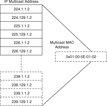
![]() A host that joins one multicast group programs its network interface card to listen to the IP-mapped MAC address. If the same MAC address maps to a second MAC multicast address already in use, the host CPU processes both sets of IP multicast frames. Furthermore, because switches forward frames based on the multicast MAC address if configured for Layer 2 multicast snooping, they forward frames to all the members corresponding to other IP multicast addresses of the same MAC address mapping, even if the frames belong to a different IP multicast group. For example, multicast IP addresses 238.1.1.2 and 238.129.1.2 both map to the same multicast MAC address 01:00:5E:01:01:02. As a result, a host that registered to group 238.1.1.2 also receives the traffic from 238:129:1.2 because the same MAC multicast address is used by both IP multicast flows. It is recommended to avoid overlapping when implementing multicast applications in the multilayer switched network by tuning the destination IP multicast addresses at the application level.
A host that joins one multicast group programs its network interface card to listen to the IP-mapped MAC address. If the same MAC address maps to a second MAC multicast address already in use, the host CPU processes both sets of IP multicast frames. Furthermore, because switches forward frames based on the multicast MAC address if configured for Layer 2 multicast snooping, they forward frames to all the members corresponding to other IP multicast addresses of the same MAC address mapping, even if the frames belong to a different IP multicast group. For example, multicast IP addresses 238.1.1.2 and 238.129.1.2 both map to the same multicast MAC address 01:00:5E:01:01:02. As a result, a host that registered to group 238.1.1.2 also receives the traffic from 238:129:1.2 because the same MAC multicast address is used by both IP multicast flows. It is recommended to avoid overlapping when implementing multicast applications in the multilayer switched network by tuning the destination IP multicast addresses at the application level.
Reverse Path Forwarding
![]() Multicast-capable routers and multilayer switches create distribution trees that control the path that IP multicast traffic takes through the network to achieve loop-free forwarding. Reverse Path Forwarding (RPF) is the mechanism that performs an incoming interface check to determine whether to forward or drop an incoming multicast frame. RPF is a key concept in multicast forwarding. This RPF check helps to guarantee that the distribution tree for multicast is loop-free. In addition, RPF enables routers to correctly forward multicast traffic down the distribution tree.
Multicast-capable routers and multilayer switches create distribution trees that control the path that IP multicast traffic takes through the network to achieve loop-free forwarding. Reverse Path Forwarding (RPF) is the mechanism that performs an incoming interface check to determine whether to forward or drop an incoming multicast frame. RPF is a key concept in multicast forwarding. This RPF check helps to guarantee that the distribution tree for multicast is loop-free. In addition, RPF enables routers to correctly forward multicast traffic down the distribution tree.
![]() In unicast routing, traffic is routed through the network along the path from the single source to the single destination host. A router that is forwarding unicast packets does not consider the source address, by default; the router considers only the destination address and how to forward the traffic toward the destination with the exception of specialized CEF features. Upon receipt of unicast packets, the router scans through its routing table for the destination address and then forwards a single copy of the unicast packet out the correct interface to the destination.
In unicast routing, traffic is routed through the network along the path from the single source to the single destination host. A router that is forwarding unicast packets does not consider the source address, by default; the router considers only the destination address and how to forward the traffic toward the destination with the exception of specialized CEF features. Upon receipt of unicast packets, the router scans through its routing table for the destination address and then forwards a single copy of the unicast packet out the correct interface to the destination.
![]() In multicast forwarding, the source is sending traffic to an arbitrary group of hosts that is represented by a single multicast group address. When a multicast router receives a multicast packet, it determines which direction is the upstream direction (toward the source) and which one is the downstream direction (toward the receivers). A router forwards a multicast packet only if the packet is received on the correct upstream interface determined by the RPF process.
In multicast forwarding, the source is sending traffic to an arbitrary group of hosts that is represented by a single multicast group address. When a multicast router receives a multicast packet, it determines which direction is the upstream direction (toward the source) and which one is the downstream direction (toward the receivers). A router forwards a multicast packet only if the packet is received on the correct upstream interface determined by the RPF process.
![]() Note, although routers build a separate IP multicast routing table, the RFP check is dependent on the unicast IP routing table for determining the correct upstream and downstream interfaces.
Note, although routers build a separate IP multicast routing table, the RFP check is dependent on the unicast IP routing table for determining the correct upstream and downstream interfaces.
![]() For traffic flowing down a source tree, the RPF check procedure works as follows:
For traffic flowing down a source tree, the RPF check procedure works as follows:
- The router looks up the source address in the unicast routing table to determine whether it arrived on the interface that is on the reverse path (lowest-cost path) back to the source.
- If the packet has arrived on the interface leading back to the source, the RPF check is successful, and the router replicates and forwards the packet to the outgoing interfaces.
- If the RPF check in the previous step fails, the router drops the packet and records the drop as an RPF failed drop.
![]() The top portion of Figure 7-27 illustrates an example where the RPF check fails. The router in the figure receives a multicast packet from source 151.10.3.21 on Interface S0. A check of the unicast route table shows that this router uses Interface S1 as the egress interface for forwarding unicast data to 151.10.3.21. Because the packet instead arrived on Interface S0, the packet fails the RPF check, and the router drops the packet. In the bottom portion of Figure 7-27, the RPF check succeeds. With this example, the multicast packet arrives on Interface S1. The router checks the unicast routing table and finds that Interface S1 is the correct ingress interface. The RPF check passes, and the router forwards the packet.
The top portion of Figure 7-27 illustrates an example where the RPF check fails. The router in the figure receives a multicast packet from source 151.10.3.21 on Interface S0. A check of the unicast route table shows that this router uses Interface S1 as the egress interface for forwarding unicast data to 151.10.3.21. Because the packet instead arrived on Interface S0, the packet fails the RPF check, and the router drops the packet. In the bottom portion of Figure 7-27, the RPF check succeeds. With this example, the multicast packet arrives on Interface S1. The router checks the unicast routing table and finds that Interface S1 is the correct ingress interface. The RPF check passes, and the router forwards the packet.


![]() In multilayer switched networks where multiple routers connect to the same LAN segment, only one router forwards the multicast traffic from the source to the receivers on the outgoing interfaces. This router is denoted as the Protocol Independent Multicast Designated Router (PIM DR) and is illustrated in Figure 7-28. Router A, the PIM-designated router (PIM DR), forwards data to VLAN 1 and VLAN 2. Router B receives the forwarded multicast traffic on VLAN 1 and VLAN 2, and it drops this traffic because the multicast traffic fails the RPF check. Traffic that fails the RPF check is called non-RPF traffic.
In multilayer switched networks where multiple routers connect to the same LAN segment, only one router forwards the multicast traffic from the source to the receivers on the outgoing interfaces. This router is denoted as the Protocol Independent Multicast Designated Router (PIM DR) and is illustrated in Figure 7-28. Router A, the PIM-designated router (PIM DR), forwards data to VLAN 1 and VLAN 2. Router B receives the forwarded multicast traffic on VLAN 1 and VLAN 2, and it drops this traffic because the multicast traffic fails the RPF check. Traffic that fails the RPF check is called non-RPF traffic.


Multicast Forwarding Tree
![]() Multicast-capable routers create multicast distribution trees that control the path that IP multicast traffic takes through the network to deliver traffic to all receivers.
Multicast-capable routers create multicast distribution trees that control the path that IP multicast traffic takes through the network to deliver traffic to all receivers.
![]() The following are the two types of distribution trees:
The following are the two types of distribution trees:
Source Trees
![]() The simplest form of a multicast distribution tree is a source tree with its root at the source and its branches forming a tree through the network to the receivers. Because this tree uses the shortest path through the network, it is also referred to as a shortest path tree (SPT).
The simplest form of a multicast distribution tree is a source tree with its root at the source and its branches forming a tree through the network to the receivers. Because this tree uses the shortest path through the network, it is also referred to as a shortest path tree (SPT).
![]() Figure 7-29 shows an example of an SPT for group 224.1.1.1 rooted at the source, Host A, and connecting two receivers, Hosts B and C.
Figure 7-29 shows an example of an SPT for group 224.1.1.1 rooted at the source, Host A, and connecting two receivers, Hosts B and C.


![]() Using the (S,G) notation, the SPT for the example shown in Figure 7-29 is (192.168.1.1, 224.1.1.1).
Using the (S,G) notation, the SPT for the example shown in Figure 7-29 is (192.168.1.1, 224.1.1.1).
![]() The (S,G) notation implies that a separate SPT exists for each source sending to each group. For example, if host B is also sending traffic to group 224.1.1.1 and Hosts A and C are receivers, a separate (S,G) SPT would exist with a notation of (192.168.2.2, 224.1.1.1).
The (S,G) notation implies that a separate SPT exists for each source sending to each group. For example, if host B is also sending traffic to group 224.1.1.1 and Hosts A and C are receivers, a separate (S,G) SPT would exist with a notation of (192.168.2.2, 224.1.1.1).
Shared Trees
![]() Unlike source trees, which have their root at the source, shared trees use a single common root placed at some chosen point in the network. This shared root is called a rendezvous point (RP). Figure 7-30 shows a shared unidirectional tree for the group 224.1.1.1 with the root located at Router D. Source traffic is sent toward the RP on a shared tree. The traffic is then forwarded down the shared tree from the RP to reach all the receivers unless the receiver is located between the source and the RP, in which case the multicast traffic is serviced directly.
Unlike source trees, which have their root at the source, shared trees use a single common root placed at some chosen point in the network. This shared root is called a rendezvous point (RP). Figure 7-30 shows a shared unidirectional tree for the group 224.1.1.1 with the root located at Router D. Source traffic is sent toward the RP on a shared tree. The traffic is then forwarded down the shared tree from the RP to reach all the receivers unless the receiver is located between the source and the RP, in which case the multicast traffic is serviced directly.


![]() In Figure 7-30 multicast traffic from the sources, Hosts A and D, travels to the root (Router D) and then down the shared tree to the two receivers, Hosts B and C. Because all sources in the multicast group use a common shared tree, a wildcard notation written as (*,G), pronounced “star comma G,” represents the tree. In this case, * means all sources, and G represents the multicast group. Therefore, the shared tree shown in the figure is written as (*, 224.1.1.1).
In Figure 7-30 multicast traffic from the sources, Hosts A and D, travels to the root (Router D) and then down the shared tree to the two receivers, Hosts B and C. Because all sources in the multicast group use a common shared tree, a wildcard notation written as (*,G), pronounced “star comma G,” represents the tree. In this case, * means all sources, and G represents the multicast group. Therefore, the shared tree shown in the figure is written as (*, 224.1.1.1).
Comparing Source Trees and Shared Trees
![]() Both source trees and shared trees avoid multicast traffic loops. Routing devices replicate the multicast packets only where the tree branches.
Both source trees and shared trees avoid multicast traffic loops. Routing devices replicate the multicast packets only where the tree branches.
![]() Members of multicast groups join or leave at any time; as a result, the distribution trees update dynamically. When all the active receivers on a particular branch stop requesting traffic for a particular multicast group, the routers prune that branch from the tree and stop forwarding traffic down it. If one receiver on that branch becomes active and requests the multicast traffic, the router dynamically modifies the distribution tree and starts forwarding traffic again.
Members of multicast groups join or leave at any time; as a result, the distribution trees update dynamically. When all the active receivers on a particular branch stop requesting traffic for a particular multicast group, the routers prune that branch from the tree and stop forwarding traffic down it. If one receiver on that branch becomes active and requests the multicast traffic, the router dynamically modifies the distribution tree and starts forwarding traffic again.
![]() Source trees have the advantage of creating the optimal path between the source and the receivers. This advantage guarantees the minimum amount of network latency for forwarding multicast traffic. However, this optimization requires additional overhead because the routers maintain path information for each source. In a network that has thousands of sources and thousands of groups, this overhead quickly becomes a resource issue on routers or multilayer switches. Memory consumption and troubleshooting complexity from the size of the multicast routing table are factors that network designers need to take into consideration when designing multicast networks.
Source trees have the advantage of creating the optimal path between the source and the receivers. This advantage guarantees the minimum amount of network latency for forwarding multicast traffic. However, this optimization requires additional overhead because the routers maintain path information for each source. In a network that has thousands of sources and thousands of groups, this overhead quickly becomes a resource issue on routers or multilayer switches. Memory consumption and troubleshooting complexity from the size of the multicast routing table are factors that network designers need to take into consideration when designing multicast networks.
![]() Shared trees have the advantage of requiring the minimum amount of state information in each router. This advantage lowers the overall memory requirements and complexity for a network that allows only shared trees. The disadvantage of shared trees is that, under certain circumstances, the paths between the source and receivers might not be the optimal paths, which can introduce additional latency in packet delivery. As a result, shared trees might overuse some links and leave others unused, whereas source-based trees (where sources are distributed) usually distribute traffic across a set of links. For example, in Figure 7-30, the shortest path between Host A (Source 1) and Host B (a receiver) is between Router A and Router C. Because Router D is the root for a shared tree, the traffic traverses Routers A, B, D, and then C. Network designers need to carefully consider the placement of the RP when implementing a shared tree–only environment.
Shared trees have the advantage of requiring the minimum amount of state information in each router. This advantage lowers the overall memory requirements and complexity for a network that allows only shared trees. The disadvantage of shared trees is that, under certain circumstances, the paths between the source and receivers might not be the optimal paths, which can introduce additional latency in packet delivery. As a result, shared trees might overuse some links and leave others unused, whereas source-based trees (where sources are distributed) usually distribute traffic across a set of links. For example, in Figure 7-30, the shortest path between Host A (Source 1) and Host B (a receiver) is between Router A and Router C. Because Router D is the root for a shared tree, the traffic traverses Routers A, B, D, and then C. Network designers need to carefully consider the placement of the RP when implementing a shared tree–only environment.
IP Multicast Protocols
![]() Similar to IP unicast, IP multicast uses its own routing, management, and Layer 2 protocols. The following are two important multicast protocols:
Similar to IP unicast, IP multicast uses its own routing, management, and Layer 2 protocols. The following are two important multicast protocols:
- Internet Group Management Protocol (IGMP)
PIM
![]() A multicast routing protocol is responsible for the construction of multicast delivery trees and enabling multicast packet forwarding. Different IP multicast routing protocols use different techniques to construct multicast trees and to forward packets. The PIM routing protocol leverages whichever unicast routing protocols are used to populate the unicast routing table to make multicast forwarding decisions.
A multicast routing protocol is responsible for the construction of multicast delivery trees and enabling multicast packet forwarding. Different IP multicast routing protocols use different techniques to construct multicast trees and to forward packets. The PIM routing protocol leverages whichever unicast routing protocols are used to populate the unicast routing table to make multicast forwarding decisions.
![]() Furthermore, routers use the PIM neighbor discovery mechanism to establish PIM neighbors using hello messages to the ALL-PIM-Routers (224.0.0.13) multicast address for building and maintaining PIM multicast distribution trees. In addition, routers use PIM hello messages to elect the designated router (DR) for a multicast LAN network.
Furthermore, routers use the PIM neighbor discovery mechanism to establish PIM neighbors using hello messages to the ALL-PIM-Routers (224.0.0.13) multicast address for building and maintaining PIM multicast distribution trees. In addition, routers use PIM hello messages to elect the designated router (DR) for a multicast LAN network.
![]() PIM encompasses two distinct versions: PIM version 1 and PIM version 2. This chapter compares the two in the section “Comparison and Compatibility of PIM Version 1 and Version 2,” later in this chapter.
PIM encompasses two distinct versions: PIM version 1 and PIM version 2. This chapter compares the two in the section “Comparison and Compatibility of PIM Version 1 and Version 2,” later in this chapter.
![]() PIM has the following four modes of operation, which are discussed in the following sections:
PIM has the following four modes of operation, which are discussed in the following sections:
![]() Sparse-dense mode is most common in large enterprise networks. There is a small movement toward bidirectional PIM in large enterprise networks; however, as of early 2010, few large enterprise adopters exist.
Sparse-dense mode is most common in large enterprise networks. There is a small movement toward bidirectional PIM in large enterprise networks; however, as of early 2010, few large enterprise adopters exist.
PIM Dense Mode
![]() PIM dense mode (PIM-DM) multicast routing protocols rely on periodic flooding of the network with multicast traffic to set up and maintain the distribution tree. PIM relies on its neighbor information to form the distribution tree. PIM-DM uses a source distribution tree to forward multicast traffic, which is built by respective routers as soon as any multicast source begins transmitting. Figure 7-31 illustrates an example of PIM-DM.
PIM dense mode (PIM-DM) multicast routing protocols rely on periodic flooding of the network with multicast traffic to set up and maintain the distribution tree. PIM relies on its neighbor information to form the distribution tree. PIM-DM uses a source distribution tree to forward multicast traffic, which is built by respective routers as soon as any multicast source begins transmitting. Figure 7-31 illustrates an example of PIM-DM.


![]() PIM Dense Mode is obsolete and no longer deployed in campus networks. This section still exists for the purpose of completeness.
PIM Dense Mode is obsolete and no longer deployed in campus networks. This section still exists for the purpose of completeness.
![]() PIM-DM assumes that the multicast group members are densely distributed throughout the network and that bandwidth is plentiful, meaning that almost all hosts on the network belong to the group. When a router configured for PIM-DM receives a multicast packet, the router performs the RPF check to validate the correct interface for the source and then forwards the packet to all the interfaces configured for multicasting until pruning and truncating occurs. All downstream routers receive the multicast packet until the multicast traffic times out. PIM-DM sends a pruning message upstream only under the following conditions:
PIM-DM assumes that the multicast group members are densely distributed throughout the network and that bandwidth is plentiful, meaning that almost all hosts on the network belong to the group. When a router configured for PIM-DM receives a multicast packet, the router performs the RPF check to validate the correct interface for the source and then forwards the packet to all the interfaces configured for multicasting until pruning and truncating occurs. All downstream routers receive the multicast packet until the multicast traffic times out. PIM-DM sends a pruning message upstream only under the following conditions:
- Traffic arrives on a non-RPF, point-to-point interface; this is the next-hop router interface that does not have a best route toward the multicast source.
- A leaf router without receivers sends a prune message, as shown in Figure 7-31, and the router, which does not have members or receivers, sends the prune message to the upstream router.
- A nonleaf router receives a prune message from all of its neighbors.
![]() In summary, PIM-DM works best when numerous members belong to each multimedia group. PIM floods the multimedia packet to all routers in the network and then prunes routers that do not service members of that particular multicast group.
In summary, PIM-DM works best when numerous members belong to each multimedia group. PIM floods the multimedia packet to all routers in the network and then prunes routers that do not service members of that particular multicast group.
![]() Consider when planning multicast in the campus network that PIM-DM is most useful in the following cases:
Consider when planning multicast in the campus network that PIM-DM is most useful in the following cases:
- Senders and receivers are in close proximity to one another.
- PIM-SM goes through a dense-mode flooding phase before fully relying on the RP for multicast forwarding.
- There are few senders and many receivers.
- The volume of multicast traffic is high.
- The stream of multicast traffic is constant.
![]() Nevertheless, PIM-DM is not the method of choice for most campus networks enterprise because of its scalability limitations and flooding properties.
Nevertheless, PIM-DM is not the method of choice for most campus networks enterprise because of its scalability limitations and flooding properties.
PIM Sparse Mode
![]() The second approach to multicast routing, PIM sparse mode (PIM-SM), is based on the assumptions that the multicast group members are sparsely distributed throughout the network and that bandwidth is limited.
The second approach to multicast routing, PIM sparse mode (PIM-SM), is based on the assumptions that the multicast group members are sparsely distributed throughout the network and that bandwidth is limited.
![]() It is important to note that PIM-SM does not imply that the group has few members, just that they are widely dispersed. In this case, flooding would unnecessarily waste network bandwidth and could cause serious performance problems. Therefore, PIM-SM multicast routing protocols rely on more selective techniques to set up and maintain multicast trees.
It is important to note that PIM-SM does not imply that the group has few members, just that they are widely dispersed. In this case, flooding would unnecessarily waste network bandwidth and could cause serious performance problems. Therefore, PIM-SM multicast routing protocols rely on more selective techniques to set up and maintain multicast trees.
![]() PIM-SM protocols begin with an empty distribution tree and add branches only as the result of explicit requests to join the distribution. Figure 7-32 illustrates a sample of PIM sparse mode.
PIM-SM protocols begin with an empty distribution tree and add branches only as the result of explicit requests to join the distribution. Figure 7-32 illustrates a sample of PIM sparse mode.


![]() With PIM-SM, each data stream goes to a relatively small number of segments in the campus network. Instead of flooding the network to determine the status of multicast members, PIM-SM defines an RP. When a sender wants to send data, it first does so to the RP. When a receiver wants to receive data, it registers with the RP, as shown in Figure 7-32. When the data stream begins to flow from sender to RP to receiver, the routers in the path automatically optimize the path to remove unnecessary hops. PIM-SM assumes that no hosts want the multicast traffic unless they specifically ask for it. In PIM-SM, the shared tree mode can be switched to a source tree after a certain threshold to have the best route to the source. All Cisco IOS routers and switches, by default, have the SPT threshold set to 0, such that the last-hop router switches to SPT mode as soon as the host starts receiving the multicast, to take advantage of the best route for the multicast traffic.
With PIM-SM, each data stream goes to a relatively small number of segments in the campus network. Instead of flooding the network to determine the status of multicast members, PIM-SM defines an RP. When a sender wants to send data, it first does so to the RP. When a receiver wants to receive data, it registers with the RP, as shown in Figure 7-32. When the data stream begins to flow from sender to RP to receiver, the routers in the path automatically optimize the path to remove unnecessary hops. PIM-SM assumes that no hosts want the multicast traffic unless they specifically ask for it. In PIM-SM, the shared tree mode can be switched to a source tree after a certain threshold to have the best route to the source. All Cisco IOS routers and switches, by default, have the SPT threshold set to 0, such that the last-hop router switches to SPT mode as soon as the host starts receiving the multicast, to take advantage of the best route for the multicast traffic.
| Note |
|
![]() PIM-SM is optimized for environments where there are many multipoint data streams. When planning for multicast deployments in the campus network, choose PIM-SM with IP under the following scenarios:
PIM-SM is optimized for environments where there are many multipoint data streams. When planning for multicast deployments in the campus network, choose PIM-SM with IP under the following scenarios:
PIM Sparse-Dense Mode
![]() PIM can simultaneously support dense mode operation for some multicast groups and sparse mode operation for others. Cisco has implemented an alternative to choosing just dense mode or just sparse mode on a router interface, however. This was necessitated by a change in the paradigm for forwarding multicast traffic via PIM that became apparent during its development. It turned out that it was more efficient to choose sparse or dense mode on a per-group basis rather than a per-router interface basis. Sparse-dense mode facilitates this ability.
PIM can simultaneously support dense mode operation for some multicast groups and sparse mode operation for others. Cisco has implemented an alternative to choosing just dense mode or just sparse mode on a router interface, however. This was necessitated by a change in the paradigm for forwarding multicast traffic via PIM that became apparent during its development. It turned out that it was more efficient to choose sparse or dense mode on a per-group basis rather than a per-router interface basis. Sparse-dense mode facilitates this ability.
![]() PIM sparse-dense mode enables individual groups to use either sparse or dense mode depending on whether RP information is available for that group. If the router learns RP information for a particular group, sparse mode is used; otherwise, dense mode is used. Note, PIM spare-dense mode is seldom used in campus networks.
PIM sparse-dense mode enables individual groups to use either sparse or dense mode depending on whether RP information is available for that group. If the router learns RP information for a particular group, sparse mode is used; otherwise, dense mode is used. Note, PIM spare-dense mode is seldom used in campus networks.
PIM Bidirectional
![]() Bidirectional PIM (bidir-PIM) is an extension of the existing PIM-SM feature and shares many SPT operations. Bidir-PIM is suited for multicast with larger numbers of sources.
Bidirectional PIM (bidir-PIM) is an extension of the existing PIM-SM feature and shares many SPT operations. Bidir-PIM is suited for multicast with larger numbers of sources.
![]() Bidir-PIM can unconditionally forward source traffic toward the RP upstream on the shared tree without registering for sources as in PIM-SM. This enables traffic to be passed up the shared tree toward the RP. To avoid multicast packet loops, bidir-PIM introduces a mechanism called designated forwarder (DF) election, which establishes a loop-free SPT rooted at the RP. The DF is responsible for forwarding multicast packets received on that network upstream to the RP. One DF exists for every RP of bidirectional groups.
Bidir-PIM can unconditionally forward source traffic toward the RP upstream on the shared tree without registering for sources as in PIM-SM. This enables traffic to be passed up the shared tree toward the RP. To avoid multicast packet loops, bidir-PIM introduces a mechanism called designated forwarder (DF) election, which establishes a loop-free SPT rooted at the RP. The DF is responsible for forwarding multicast packets received on that network upstream to the RP. One DF exists for every RP of bidirectional groups.
![]() A router creates only (*,G) entries for bidirectional groups. The outgoing interface list of multicast traffic (olist) of a (*,G) entry includes all the interfaces for which the router has been elected as DF and that have received either an IGMP or a PIM join message. If a packet is received from the RPF interface toward the RP, the packet is forwarded downstream according to the olist of the (*,G) entry. Otherwise, when the router that is DF for the receiving interface forwards the packet toward the RP, all other routers must discard the packet. These modifications are necessary and sufficient to enable forwarding of traffic in all routers based solely on the (*, G) multicast routing entries. This feature eliminates any source-specific state and enables scaling capability to an arbitrary number of sources.
A router creates only (*,G) entries for bidirectional groups. The outgoing interface list of multicast traffic (olist) of a (*,G) entry includes all the interfaces for which the router has been elected as DF and that have received either an IGMP or a PIM join message. If a packet is received from the RPF interface toward the RP, the packet is forwarded downstream according to the olist of the (*,G) entry. Otherwise, when the router that is DF for the receiving interface forwards the packet toward the RP, all other routers must discard the packet. These modifications are necessary and sufficient to enable forwarding of traffic in all routers based solely on the (*, G) multicast routing entries. This feature eliminates any source-specific state and enables scaling capability to an arbitrary number of sources.
Automating Distribution of RP
![]() PIM-SM and PIM sparse-dense modes use various methods, discussed in this section, to automate the distribution of the RP. This mechanism has the following benefits:
PIM-SM and PIM sparse-dense modes use various methods, discussed in this section, to automate the distribution of the RP. This mechanism has the following benefits:
- It eliminates the need to manually configure RP information in every router and switch in the network.
- It is easy to use multiple RPs within a network to serve different group ranges.
- It enables load-splitting among different RPs and enables the arrangement of RPs according to the location of group participants.
- It avoids inconsistency; manual RP configurations may cause connectivity problems if not configured properly.
![]() PIM uses the following mechanisms to automate the distribution of the RP:
PIM uses the following mechanisms to automate the distribution of the RP:
- Anycast-RP
- MSDPAnycast-RP and MSDP are outside the context of SWITCH; more information about these mechanisms can be found on Cisco.com.
Auto-RP
![]() Auto-RP automates the distribution of group-to-RP mappings in a PIM network. Group-to-RP mappings define which multicast groups use which RP for sparse mode or sparse-dense mode.
Auto-RP automates the distribution of group-to-RP mappings in a PIM network. Group-to-RP mappings define which multicast groups use which RP for sparse mode or sparse-dense mode.
![]() All routers and Layer 3 devices in the PIM network learn about the active group-to-RP mapping from the RP mapping agent by automatically joining the Cisco-RP-discovery (224.0.1.40) multicast group. The RP mapping agent is the router that sends the authoritative discovery packets that notify other routers which group-to-RP mapping to use, as shown in Figure 7-33. The RP mapping agent sends this information every 60 seconds. Such a role is necessary if conflicts occur (such as overlapping group-to-RP ranges).
All routers and Layer 3 devices in the PIM network learn about the active group-to-RP mapping from the RP mapping agent by automatically joining the Cisco-RP-discovery (224.0.1.40) multicast group. The RP mapping agent is the router that sends the authoritative discovery packets that notify other routers which group-to-RP mapping to use, as shown in Figure 7-33. The RP mapping agent sends this information every 60 seconds. Such a role is necessary if conflicts occur (such as overlapping group-to-RP ranges).


![]() Mapping agents also use IP multicast to discover which routers in the network are possible candidate RPs by joining the Cisco-RP-announce (224.0.1.39) group to receive candidate RP announcements. Candidate RPs send RP-announce multicast messages for the particular groups every 60 seconds. The RP mapping agent uses the information contained in the announcement to create entries in group-to-RP cache. RP mapping agents create only one entry per group. If more than one RP candidate announces the same range, the RP mapping agent uses the IP address of the RP to break the tie.
Mapping agents also use IP multicast to discover which routers in the network are possible candidate RPs by joining the Cisco-RP-announce (224.0.1.39) group to receive candidate RP announcements. Candidate RPs send RP-announce multicast messages for the particular groups every 60 seconds. The RP mapping agent uses the information contained in the announcement to create entries in group-to-RP cache. RP mapping agents create only one entry per group. If more than one RP candidate announces the same range, the RP mapping agent uses the IP address of the RP to break the tie.
![]() It is recommended that an RP mapping agent be configured on the router with the best connectivity and stability. All routers within the TTL number of hops from the RP mapping router receive the Auto-RP discovery messages.
It is recommended that an RP mapping agent be configured on the router with the best connectivity and stability. All routers within the TTL number of hops from the RP mapping router receive the Auto-RP discovery messages.
![]() Sparse mode environments require a default RP to join the Auto-RP discovery group, but sparse-dense mode environments do not need a default RP for Auto-RP. It is recommended to use RP for the global groups. There is no need to reconfigure the group address range that the RP serves. RPs that are discovered dynamically through Auto-RP take precedence over statically configured RPs. Typically, campus networks use a second RP for the local groups.
Sparse mode environments require a default RP to join the Auto-RP discovery group, but sparse-dense mode environments do not need a default RP for Auto-RP. It is recommended to use RP for the global groups. There is no need to reconfigure the group address range that the RP serves. RPs that are discovered dynamically through Auto-RP take precedence over statically configured RPs. Typically, campus networks use a second RP for the local groups.
Bootstrap Router
![]() A bootstrap router (BSR) is a router or Layer 3 device that is responsible for distributing RP. Using a BSR is another way to distribute group-to-RP mapping information in the PIM multicast network. However, BSR works only with PIM version 2. A BSR uses hop-to-hop flooding of special BSR messages instead of multicast to distribute the group-to-RP mapping.
A bootstrap router (BSR) is a router or Layer 3 device that is responsible for distributing RP. Using a BSR is another way to distribute group-to-RP mapping information in the PIM multicast network. However, BSR works only with PIM version 2. A BSR uses hop-to-hop flooding of special BSR messages instead of multicast to distribute the group-to-RP mapping.
![]() BSR uses an election mechanism to select the BSR router from a set of candidate routers and multilayer switches in the domain. The BSR election uses the BSR priority of the device contained in the BSR messages that flow hop-by-hop through the network. Each BSR device examines the message and forwards it out all interfaces only if the message has either a higher BSR priority than the router’s own BSR priority or has the same BSR priority but with a higher BSR IP address.
BSR uses an election mechanism to select the BSR router from a set of candidate routers and multilayer switches in the domain. The BSR election uses the BSR priority of the device contained in the BSR messages that flow hop-by-hop through the network. Each BSR device examines the message and forwards it out all interfaces only if the message has either a higher BSR priority than the router’s own BSR priority or has the same BSR priority but with a higher BSR IP address.
![]() The elected BSR sends BSR messages with a TTL of 1 with its IP address to enable candidate BSRs to learn automatically about the elected BSR. Neighboring PIM version 2 routers or multilayer switches receive the BSR message and multicast the message out all other interfaces (except the one on which it was received) with a TTL of 1 to distribute the BSR messages hop-by-hop, as shown in Figure 7-34.
The elected BSR sends BSR messages with a TTL of 1 with its IP address to enable candidate BSRs to learn automatically about the elected BSR. Neighboring PIM version 2 routers or multilayer switches receive the BSR message and multicast the message out all other interfaces (except the one on which it was received) with a TTL of 1 to distribute the BSR messages hop-by-hop, as shown in Figure 7-34.


![]() Candidate RPs send candidate RP advertisements showing the group range for which each is responsible to the BSR, which stores this information in its local candidate RP cache. The BSR includes this information in its bootstrap messages and disseminates it to all PIM routers using 224.0.0.13 with a TTL of 1 in the domain hop-by-hop. Based on this information, all routers can map multicast groups to specific RPs. As long as a router is receiving the bootstrap message, it has a current RP map. Routers and multilayer switches select the same RP for a given group because they all use a common RP hashing algorithm.
Candidate RPs send candidate RP advertisements showing the group range for which each is responsible to the BSR, which stores this information in its local candidate RP cache. The BSR includes this information in its bootstrap messages and disseminates it to all PIM routers using 224.0.0.13 with a TTL of 1 in the domain hop-by-hop. Based on this information, all routers can map multicast groups to specific RPs. As long as a router is receiving the bootstrap message, it has a current RP map. Routers and multilayer switches select the same RP for a given group because they all use a common RP hashing algorithm.
Comparison and Compatibility of PIM Version 1 and Version 2
![]() PIM version 2 is a standards-based multicast protocol in the Internet Engineering Task Force (IETF). Cisco highly recommends using PIM version 2 in the entire multilayer switched network. The Cisco PIM version 2 implementation enables interoperability and transition between version 1 and version 2, although there are a few caveats. For example, if a PIM version 2 router detects a PIM version 1 router, the version 2 router downgrades itself to version 1 until all version 1 routers have been shut down or upgraded.
PIM version 2 is a standards-based multicast protocol in the Internet Engineering Task Force (IETF). Cisco highly recommends using PIM version 2 in the entire multilayer switched network. The Cisco PIM version 2 implementation enables interoperability and transition between version 1 and version 2, although there are a few caveats. For example, if a PIM version 2 router detects a PIM version 1 router, the version 2 router downgrades itself to version 1 until all version 1 routers have been shut down or upgraded.
![]() PIM version 2 uses the BSR to discover and announce RP-to-group mapping information for each group prefix to all the routers in a PIM domain. This is the same function accomplished by Auto-RP. However, the BSR feature is part of the PIM version 2 specifications because bootstrap messages are sent on a hop-by-hop basis, and a PIM version 1 router prevents these messages from reaching all routers in a network. Therefore, if a network has a PIM version 1 router with Cisco routers, it is best to use Auto-RP rather than the bootstrap mechanism. Nevertheless, Auto-RP is a standalone protocol, separate from PIM version 1, and is Cisco proprietary. The BSR mechanism interoperates with Auto-RP on Cisco routers.
PIM version 2 uses the BSR to discover and announce RP-to-group mapping information for each group prefix to all the routers in a PIM domain. This is the same function accomplished by Auto-RP. However, the BSR feature is part of the PIM version 2 specifications because bootstrap messages are sent on a hop-by-hop basis, and a PIM version 1 router prevents these messages from reaching all routers in a network. Therefore, if a network has a PIM version 1 router with Cisco routers, it is best to use Auto-RP rather than the bootstrap mechanism. Nevertheless, Auto-RP is a standalone protocol, separate from PIM version 1, and is Cisco proprietary. The BSR mechanism interoperates with Auto-RP on Cisco routers.
![]() A PIM version 2 BSR that is also an Auto-RP mapping agent automatically advertises the RP elected by Auto-RP. That is, Auto-RP prevails in its imposition of a single RP on every router in the group.
A PIM version 2 BSR that is also an Auto-RP mapping agent automatically advertises the RP elected by Auto-RP. That is, Auto-RP prevails in its imposition of a single RP on every router in the group.
![]() In summary, PIM version 2 includes the following improvements over PIM version 1:
In summary, PIM version 2 includes the following improvements over PIM version 1:
- A single, active RP exists per multicast group, with multiple backup RPs. This single RP compares to multiple active RPs for the same group in PIM version 1.
- A BSR provides a fault-tolerant, automated RP discovery and distribution mechanism. Thus, routers dynamically learn the group-to-RP mappings.
- Sparse mode and dense mode are properties of a group, as opposed to an interface. Cisco strongly recommends sparse-dense mode configurations.
- PIM join and prune messages have more flexible encodings for multiple address families.
- A more flexible hello packet format replaces the query packet to encode current and future capability options.
- Register messages to an RP indicate whether they were sent by a border router or a designated router.
- PIM no longer uses the IGMP protocol for transport; PIM version 2 uses standalone packets.
![]() When planning for PIM deployments in the campus network, prefer to use PIM version 2 over PIM version 1.
When planning for PIM deployments in the campus network, prefer to use PIM version 2 over PIM version 1.
| Note |
|
Configuring Internet Group Management Protocol
![]() Hosts use IGMP to dynamically register themselves in a multicast group on a particular LAN. Hosts identify group memberships by sending IGMP messages to their local designated multicast router. Routers and multilayer switches, configured for IGMP, listen to IGMP messages and periodically send out queries to discover which groups are active or inactive on a particular subnet or VLAN.
Hosts use IGMP to dynamically register themselves in a multicast group on a particular LAN. Hosts identify group memberships by sending IGMP messages to their local designated multicast router. Routers and multilayer switches, configured for IGMP, listen to IGMP messages and periodically send out queries to discover which groups are active or inactive on a particular subnet or VLAN.
![]() The following list indicates the current versions of IGMP:
The following list indicates the current versions of IGMP:
IGMPv1
![]() According to the IGMPv1 specification, one multicast router per LAN must periodically transmit host membership query messages to determine which host groups have members on the router’s directly attached LAN networks. IGMP query messages are addressed to the all-host group (224.0.0.1) and have an IP TTL equal to 1. A TTL of 1 ensures that the corresponding router does not forward the query messages to any other multicast router.
According to the IGMPv1 specification, one multicast router per LAN must periodically transmit host membership query messages to determine which host groups have members on the router’s directly attached LAN networks. IGMP query messages are addressed to the all-host group (224.0.0.1) and have an IP TTL equal to 1. A TTL of 1 ensures that the corresponding router does not forward the query messages to any other multicast router.
![]() When the end station receives an IGMP query message, the end station responds with a host membership report for each group to which the end station belongs.
When the end station receives an IGMP query message, the end station responds with a host membership report for each group to which the end station belongs.
IGMPv2
![]() Version 2 of IGMP made several enhancements to the previous version, including the definition of a group-specific query. The group-specific query message enables a router to transmit a specific query to one particular group. IGMPv2 also defines a leave group message for the hosts, which results in lower leave latency.
Version 2 of IGMP made several enhancements to the previous version, including the definition of a group-specific query. The group-specific query message enables a router to transmit a specific query to one particular group. IGMPv2 also defines a leave group message for the hosts, which results in lower leave latency.
![]() There are four types of IGMP messages of concern to the host-router interaction:
There are four types of IGMP messages of concern to the host-router interaction:
- Membership query
- Version 2 membership report
- Leave report
- Version 1 membership report
![]() IGMPv2 uses the IGMPv1 membership report for backward compatibility with IGMPv1. Newer versions of IGMP or multicast routing protocols use new message types. Any other or unrecognized message types are ignored.
IGMPv2 uses the IGMPv1 membership report for backward compatibility with IGMPv1. Newer versions of IGMP or multicast routing protocols use new message types. Any other or unrecognized message types are ignored.
IGMPv3
![]() IGMPv3 is the next step in the evolution of IGMP. IGMPv3 adds support for source filtering that enables a multicast receiver to signal to a router the groups from which it wants to receive multicast traffic and from which sources to expect traffic. This membership information enables Cisco IOS Software to forward traffic from only those sources from which receivers requested the traffic.
IGMPv3 is the next step in the evolution of IGMP. IGMPv3 adds support for source filtering that enables a multicast receiver to signal to a router the groups from which it wants to receive multicast traffic and from which sources to expect traffic. This membership information enables Cisco IOS Software to forward traffic from only those sources from which receivers requested the traffic.
![]() In IGMPv3, the following types of IGMP messages exist:
In IGMPv3, the following types of IGMP messages exist:
- Version 3 membership query
- Version 3 membership report
![]() IGMPv3 supports applications that explicitly signal sources from which they want to receive traffic. With IGMPv3, receivers signal membership to a multicast host group in one of the following two modes:
IGMPv3 supports applications that explicitly signal sources from which they want to receive traffic. With IGMPv3, receivers signal membership to a multicast host group in one of the following two modes:
- INCLUDE mode: The receiver announces membership to a host group and provides a list of source addresses (the INCLUDE list) from which it wants to receive traffic.
- EXCLUDE mode: The receiver announces membership to a multicast group and provides a list of source addresses (the EXCLUDE list) from which it does not want to receive traffic. The host receives traffic only from sources whose IP addresses are not listed in the EXCLUDE list. To receive traffic from all sources, which is the behavior of IGMPv2, a host uses EXCLUDE mode membership with an empty EXCLUDE list.
IGMPv3 Lite
![]() IGMPv3 lite is a Cisco-developed transitional solution for application developers to immediately start programming applications for SSM. Specifically, IGMPv3 lite enables application developers to write and run SSM applications on hosts that do not yet support IGMPv3 in their operating system kernel.
IGMPv3 lite is a Cisco-developed transitional solution for application developers to immediately start programming applications for SSM. Specifically, IGMPv3 lite enables application developers to write and run SSM applications on hosts that do not yet support IGMPv3 in their operating system kernel.
![]() Applications require the Host Side IGMP Library (HSIL) for IGMPv3 lite. This software library provides applications with a subset of the IGMPv3 API required to write SSM applications. HSIL was developed for Cisco by Talarian.
Applications require the Host Side IGMP Library (HSIL) for IGMPv3 lite. This software library provides applications with a subset of the IGMPv3 API required to write SSM applications. HSIL was developed for Cisco by Talarian.
![]() One part of the HSIL is a client library linked to the SSM application. It provides the SSM subset of the IGMPv3 API to the SSM application. If possible, the library checks whether the operating system kernel supports IGMPv3. If it does, the API calls simply are passed through to the kernel. If the kernel does not support IGMPv3, the library uses the IGMPv3 lite mechanism.
One part of the HSIL is a client library linked to the SSM application. It provides the SSM subset of the IGMPv3 API to the SSM application. If possible, the library checks whether the operating system kernel supports IGMPv3. If it does, the API calls simply are passed through to the kernel. If the kernel does not support IGMPv3, the library uses the IGMPv3 lite mechanism.
![]() When using the IGMPv3 lite mechanism, the library tells the operating system kernel to join to the whole multicast group, because joining to the whole group is the only method for the application to receive traffic for that multicast group for IGMPv1 or IGMPv2. In addition, the library signals the (S,G) channel subscriptions to an IGMPv3 lite server process. A server process is needed because multiple SSM applications might be on the same host. This server process then sends IGMPv3 lite-specific (S,G) channel subscriptions to the last-hop Cisco IOS router or multilayer switch.
When using the IGMPv3 lite mechanism, the library tells the operating system kernel to join to the whole multicast group, because joining to the whole group is the only method for the application to receive traffic for that multicast group for IGMPv1 or IGMPv2. In addition, the library signals the (S,G) channel subscriptions to an IGMPv3 lite server process. A server process is needed because multiple SSM applications might be on the same host. This server process then sends IGMPv3 lite-specific (S,G) channel subscriptions to the last-hop Cisco IOS router or multilayer switch.
![]() This Cisco IOS router or multilayer switch then sees both the IGMPv1 or IGMPv2 group membership report from the operating system kernel and the (S,G) channel subscription from the HSIL daemon. If the router sees both of these messages, it interprets them as an SSM (S,G) channel subscription and joins the channel through PIM-SM. Refer to the documentation accompanying the HSIL software for more information on how to use IGMPv3 lite with your application.
This Cisco IOS router or multilayer switch then sees both the IGMPv1 or IGMPv2 group membership report from the operating system kernel and the (S,G) channel subscription from the HSIL daemon. If the router sees both of these messages, it interprets them as an SSM (S,G) channel subscription and joins the channel through PIM-SM. Refer to the documentation accompanying the HSIL software for more information on how to use IGMPv3 lite with your application.
IGMP Snooping
![]() IGMP snooping is an IP multicast constraining mechanism that examines Layer 2 and Layer 3 IP multicast information to maintain a Layer 2 multicast forwarding table. This constrains multicast traffic at Layer 2 by configuring Layer 2 LAN ports dynamically to forward multicast traffic only to those ports that want to receive it.
IGMP snooping is an IP multicast constraining mechanism that examines Layer 2 and Layer 3 IP multicast information to maintain a Layer 2 multicast forwarding table. This constrains multicast traffic at Layer 2 by configuring Layer 2 LAN ports dynamically to forward multicast traffic only to those ports that want to receive it.
![]() IGMP snooping operates on multilayer switches, even switches that do not support Layer 3 routing. IGMP snooping requires the LAN switch to examine, or “snoop,” the IGMP join and leave messages sent between hosts and the first-hop designated multicast router.
IGMP snooping operates on multilayer switches, even switches that do not support Layer 3 routing. IGMP snooping requires the LAN switch to examine, or “snoop,” the IGMP join and leave messages sent between hosts and the first-hop designated multicast router.
![]() When the host joins multicast groups either by sending an unsolicited IGMP join message or by sending an IGMP join message in response to a general query from a multicast router, the switch sees an IGMP host report packet from a host for joining a particular multicast group. The switch snoops the IGMP packets and adds the host’s interface from which the IGMP report packet originated to the associated multicast Layer 2 forwarding table entry. IGMP snooping forwards only the first host join message per multicast group to the multicast routers and suppresses the rest of the joining messages for that multicast group. The switch receives the multicast traffic from the multicast router for that group specified in the join message and forwards that multicast traffic to the interfaces where join messages were received.
When the host joins multicast groups either by sending an unsolicited IGMP join message or by sending an IGMP join message in response to a general query from a multicast router, the switch sees an IGMP host report packet from a host for joining a particular multicast group. The switch snoops the IGMP packets and adds the host’s interface from which the IGMP report packet originated to the associated multicast Layer 2 forwarding table entry. IGMP snooping forwards only the first host join message per multicast group to the multicast routers and suppresses the rest of the joining messages for that multicast group. The switch receives the multicast traffic from the multicast router for that group specified in the join message and forwards that multicast traffic to the interfaces where join messages were received.
![]() When hosts want to leave a multicast group, either they ignore the periodic general IGMP queries sent by the multicast router (a process known as silent leave) or they send a group-specific IGMPv2 leave message. When the switch receives a group-specific IGMPv2 leave message from a host, the switch responds with a MAC-based group-specific query to determine whether any other devices connected on that VLAN are interested in receiving multicast traffic for the specific multicast group. If the switch does not receive an IGMP join message in response to the general query, the switch removes the table entry of the host. If the last leave message was from the only host in the group and the switch does not receive an IGMP join message in response to the general query, it removes the group entry and relays the IGMP leave message to the multicast router. The first-hop designated router then removes the group from that interface and stops forwarding multicast traffic on the interface for the group specified in the leave message.
When hosts want to leave a multicast group, either they ignore the periodic general IGMP queries sent by the multicast router (a process known as silent leave) or they send a group-specific IGMPv2 leave message. When the switch receives a group-specific IGMPv2 leave message from a host, the switch responds with a MAC-based group-specific query to determine whether any other devices connected on that VLAN are interested in receiving multicast traffic for the specific multicast group. If the switch does not receive an IGMP join message in response to the general query, the switch removes the table entry of the host. If the last leave message was from the only host in the group and the switch does not receive an IGMP join message in response to the general query, it removes the group entry and relays the IGMP leave message to the multicast router. The first-hop designated router then removes the group from that interface and stops forwarding multicast traffic on the interface for the group specified in the leave message.
![]() IGMP snooping supports the fast-leave processing feature, which allows IGMP snooping to remove a Layer 2 interface from the multicast forwarding table without first responding with IGMP group-specific queries to the host port. Upon receiving a group-specific IGMP version 2 or 3 leave message, the switch immediately removes the interface from the Layer 2 forwarding table entry for that multicast group, unless a multicast router is detected on the respective interface. Fast-leave processing improves bandwidth management for all hosts in a VLAN on a multilayer switched network.
IGMP snooping supports the fast-leave processing feature, which allows IGMP snooping to remove a Layer 2 interface from the multicast forwarding table without first responding with IGMP group-specific queries to the host port. Upon receiving a group-specific IGMP version 2 or 3 leave message, the switch immediately removes the interface from the Layer 2 forwarding table entry for that multicast group, unless a multicast router is detected on the respective interface. Fast-leave processing improves bandwidth management for all hosts in a VLAN on a multilayer switched network.
![]() The IGMP protocol transmits messages as IP multicast packets; as a result, switches cannot distinguish IGMP packets from normal IP multicast data at Layer 2. Therefore, a switch running IGMP snooping must examine every multicast data packet to determine whether it contains pertinent IGMP control information. If IGMP snooping is implemented on a low-end switch with a slow CPU, this could have a severe performance impact when data is transmitted at high rates. The solution to this problem is to implement IGMP snooping with special ASICs that can perform IGMP snooping in hardware.
The IGMP protocol transmits messages as IP multicast packets; as a result, switches cannot distinguish IGMP packets from normal IP multicast data at Layer 2. Therefore, a switch running IGMP snooping must examine every multicast data packet to determine whether it contains pertinent IGMP control information. If IGMP snooping is implemented on a low-end switch with a slow CPU, this could have a severe performance impact when data is transmitted at high rates. The solution to this problem is to implement IGMP snooping with special ASICs that can perform IGMP snooping in hardware.
![]() To configure IGMP snooping on a Cisco IOS switch, perform the following steps:
To configure IGMP snooping on a Cisco IOS switch, perform the following steps:
|
|
|
|
|
|
|
|
|
|
|
|
|
|
|
| Note |
|
![]() To configure IP multicast on Catalyst switches running Cisco IOS, perform the following steps:
To configure IP multicast on Catalyst switches running Cisco IOS, perform the following steps:
![]() Example 7-1 shows a sample configuration of PIM sparse mode in Cisco IOS with an RP address of 10.20.1.254.
Example 7-1 shows a sample configuration of PIM sparse mode in Cisco IOS with an RP address of 10.20.1.254.
Router(config)# ip multicast-routing
Router(config)# interface vlan 1
Router(config-if)# ip pim sparse-mode
Router(config-if)# interface vlan 3
Router(config-if)# ip pim sparse-mode
Router(config-if)# exit
Router(config)# ip pim rp-address 10.20.1.254
![]() Example 7-2 shows a sample configuration of PIM sparse-dense mode in Cisco IOS with a candidate BSR.
Example 7-2 shows a sample configuration of PIM sparse-dense mode in Cisco IOS with a candidate BSR.
Router(config)# interface vlan 1
Router(config-if)# ip pim sparse-dense-mode
Router(config-if)# exit
Router(config)# ip pim bsr-candidate vlan 1 30 200
![]() Example 7-3 shows a sample Cisco IOS configuration of the Auto-RP that is advertising the IP address of VLAN 1 as the RP.
Example 7-3 shows a sample Cisco IOS configuration of the Auto-RP that is advertising the IP address of VLAN 1 as the RP.
Router(config)# interface vlan 1
Router(config-if)# ip pim sparse-dense-mode
Router(config-if)# exit
Router(config)# ip pim send-rp-announce vlan 1 scope 15 group-list 1
Router(config)# access-list 1 permit 225.25.25.0.0.0.0.255
Router(config)# exit
![]() In addition to the preceding commands, every Cisco switch supports additional multicast tuning features such as rate limiting and altering the protocol timers. Refer to the product documentation for more information.
In addition to the preceding commands, every Cisco switch supports additional multicast tuning features such as rate limiting and altering the protocol timers. Refer to the product documentation for more information.
0 comments
Post a Comment