
Preparing the Campus Infrastructure to Support Wireless
![]() As previously noted, WLANs replace the Layer 1 transmission medium of a traditional wired network radio transmission over the air. This section focuses on the specific scenario’s around a campus network deployment.
As previously noted, WLANs replace the Layer 1 transmission medium of a traditional wired network radio transmission over the air. This section focuses on the specific scenario’s around a campus network deployment.
 Wireless LAN Parameters
![]() Supporting wireless requires additional WLAN preparation beyond the campus network implementation. Foremost, range, interference, performance, and security must be properly planned and prepared before campus network integration of the solution. This section focuses on deploying wireless in terms of its network connectivity to the Cisco switches. Planning for wireless range, interference, performance, and security are outside the scope of this book. The next section begins the discussion of preparing the campus network to support wireless with the standalone WLAN solution.
Supporting wireless requires additional WLAN preparation beyond the campus network implementation. Foremost, range, interference, performance, and security must be properly planned and prepared before campus network integration of the solution. This section focuses on deploying wireless in terms of its network connectivity to the Cisco switches. Planning for wireless range, interference, performance, and security are outside the scope of this book. The next section begins the discussion of preparing the campus network to support wireless with the standalone WLAN solution.
Configuring Switches to Support WLANs
![]() The configuration for supporting WLANs in the campus is broken down into two sections focusing on the standalone and controller-based solution, respectively.
The configuration for supporting WLANs in the campus is broken down into two sections focusing on the standalone and controller-based solution, respectively.
Preparing the Campus Network for Integration of a Standalone WLAN Solution
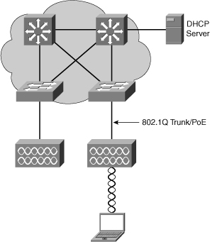
![]() The access layer switch port configuration for standalone access points is straightforward. As a best practice, the switch and the access port interface are configured as a trunk port and carry at least a data and management VLAN. The management VLAN is used for administrative purposes and might or might not be the native VLAN. There can be one or more data VLANs. If there is more than one VLAN, each VLAN will be associated to different SSIDs. Upon associating to one of the available SSIDs, the wireless client becomes a station within the VLAN and associated IP subnet. For more information on SSIDs, consult basic WLAN information on Cisco.com.
The access layer switch port configuration for standalone access points is straightforward. As a best practice, the switch and the access port interface are configured as a trunk port and carry at least a data and management VLAN. The management VLAN is used for administrative purposes and might or might not be the native VLAN. There can be one or more data VLANs. If there is more than one VLAN, each VLAN will be associated to different SSIDs. Upon associating to one of the available SSIDs, the wireless client becomes a station within the VLAN and associated IP subnet. For more information on SSIDs, consult basic WLAN information on Cisco.com.
![]() Moreover, the switch might be configured to support Power over Ethernet (PoE); however, PoE is not a requirement, rather a feature to ease installations. PoE is covered more in the next section on voice in campus network as PoE is more commonly associated with voice installations. Lastly, as with any WLAN deployment, a DHCP server provides IP addresses, DNS, and so on for the access points and the wireless clients.
Moreover, the switch might be configured to support Power over Ethernet (PoE); however, PoE is not a requirement, rather a feature to ease installations. PoE is covered more in the next section on voice in campus network as PoE is more commonly associated with voice installations. Lastly, as with any WLAN deployment, a DHCP server provides IP addresses, DNS, and so on for the access points and the wireless clients.
![]() A model of this integration is illustrated in Figure 7-35.
A model of this integration is illustrated in Figure 7-35.
Preparing the Campus Network for Integration of a Controller-Based WLAN Solution
![]() As with the standalone WLAN solution, the switch and the access port interface are configured as trunk port and carry at least a data and management VLAN. The management VLAN is used for administrative purposes and might or might not be the native VLAN. There can be one or more data VLANs.
As with the standalone WLAN solution, the switch and the access port interface are configured as trunk port and carry at least a data and management VLAN. The management VLAN is used for administrative purposes and might or might not be the native VLAN. There can be one or more data VLANs.
![]() Of note, the VLAN configured on the access points are not required to be the same VLANs configure on the controller. This is because the controller and the access points can be in different IP subnets.
Of note, the VLAN configured on the access points are not required to be the same VLANs configure on the controller. This is because the controller and the access points can be in different IP subnets.
![]() Different than the standalone WLAN solution, the mapping of the SSID, VLAN, QoS, and IP subnet is done by the WLAN controller. When a client associates to an SSID on an access point, the client becomes a station within that VLAN and associated subnet connected to the WLAN controller. The wireless client then gets an IP address from the VLAN connected to the WLAN controller that is mapped to the SSID used by the client.
Different than the standalone WLAN solution, the mapping of the SSID, VLAN, QoS, and IP subnet is done by the WLAN controller. When a client associates to an SSID on an access point, the client becomes a station within that VLAN and associated subnet connected to the WLAN controller. The wireless client then gets an IP address from the VLAN connected to the WLAN controller that is mapped to the SSID used by the client.
![]() Any VLAN can be connected to the access point. All traffic arriving at the access point is encapsulated and sent to the controller. Therefore, a clear differentiation is made between the client VLAN and the access point VLAN. Therefore, the access point and the WLAN controller can be on same or different IP subnets, and there can be a Layer 3 IP router between access point and WLAN controller.
Any VLAN can be connected to the access point. All traffic arriving at the access point is encapsulated and sent to the controller. Therefore, a clear differentiation is made between the client VLAN and the access point VLAN. Therefore, the access point and the WLAN controller can be on same or different IP subnets, and there can be a Layer 3 IP router between access point and WLAN controller.
![]() In this configuration, Layer 2 and Layer 3 roaming are supported by the WLAN controller, whether the access points connect to the same or to different controllers that are part of the same group. Figure 7-36 illustrates the behavior of the controller-based solution described.
In this configuration, Layer 2 and Layer 3 roaming are supported by the WLAN controller, whether the access points connect to the same or to different controllers that are part of the same group. Figure 7-36 illustrates the behavior of the controller-based solution described.


![]() In the case of an HREAP, some WLANs are centrally switched, which means that data for these WLANs is encapsulated and sent to the controller, just like a standard controller-based access point. Some other WLANs are locally switched, which means that traffic is sent to the switch local to the HREAP and not sent to the controller.
In the case of an HREAP, some WLANs are centrally switched, which means that data for these WLANs is encapsulated and sent to the controller, just like a standard controller-based access point. Some other WLANs are locally switched, which means that traffic is sent to the switch local to the HREAP and not sent to the controller.
![]() The consequence of this behavior is that the port to an HREAP must be a 802.1Q trunk. The native VLAN is the HREAP VLAN that communicates with the controller.
The consequence of this behavior is that the port to an HREAP must be a 802.1Q trunk. The native VLAN is the HREAP VLAN that communicates with the controller.
| Note |
|
![]() In review, the configuration of Cisco switches connected to access points are simply trunk ports. Earlier chapters covered specific configuration of trunk ports; review the configuration details in those chapters for specific configuration outside. The next section goes over preparation details for voice.
In review, the configuration of Cisco switches connected to access points are simply trunk ports. Earlier chapters covered specific configuration of trunk ports; review the configuration details in those chapters for specific configuration outside. The next section goes over preparation details for voice.
Preparing the Campus Infrastructure to Support Voice
![]() Implementing voice in a campus network requires close cooperation between network engineers and enterprise voice specialist. Voice integration needs to be planned thoroughly to integrate seamlessly into an existing campus network. When you reach the implementation phase, you need to configure the access switches for VoIP support. This section describes the step involved in the configuration required to support VoIP on campus switches. It also describes a simple test plan that can be used so that a phone properly communicates and integrates to the network infrastructure.
Implementing voice in a campus network requires close cooperation between network engineers and enterprise voice specialist. Voice integration needs to be planned thoroughly to integrate seamlessly into an existing campus network. When you reach the implementation phase, you need to configure the access switches for VoIP support. This section describes the step involved in the configuration required to support VoIP on campus switches. It also describes a simple test plan that can be used so that a phone properly communicates and integrates to the network infrastructure.
IP Telephony Components
![]() The following list of IP telephony components reviews devices commonly found deployed in the campus networks:
The following list of IP telephony components reviews devices commonly found deployed in the campus networks:
- IP Phones: Support calls in an IP telephony network. They perform voice-to-IP (and vice versa) coding and compression using special hardware. IP Phones offer services such as user directory lookups and Internet access for stock quotes. The telephones are active network devices and require power for their operation. Typically, a network connection or an external power supply provides the power.
- Switches with inline power: Enable a modular wiring-closet infrastructure to provide centralized power for Cisco IP telephony networks. These switches are similar to traditional switches, with an option to provide power to the LAN ports where IP phones are connected. In addition, they perform some basic QoS mechanisms, such as packet classification, which is a baseline for prioritizing voice through the network.
- Call-processing manager: Cisco Unified Communications Manager provides central call control and configuration management for IP Phones. Cisco Unified Communications Manager provides the core functionality to initialize IP telephony devices and perform call setup and routing of calls throughout the network. Cisco Unified Communications Manager supports clustering, which provides a distributed scalable and highly available IP telephony model. In small or remote networks, Cisco offers a router-based solution for call-processing. This solution is referred to as Cisco Unified Communications Manager Express (CUCME).
- Voice gateway: Also called voice-enabled routers or switches, voice gateways provide voice services such as voice-to-IP coding and compression, PSTN access, IP packet routing, backup call processing, and voice services. Backup call processing enables voice gateways to take over call processing if the primary call-processing manager fails. Typically, voice gateways support a subset of the call-processing functionality supported by CUCM.
![]() Recall from the voice planning section of this chapter that voice traffic has specific requirements. The voice flow needs steady pace and constant bandwidth to operate free of delay and jitter issues. Therefore, the first requirement for voice traffic integration is to implement QoS, which addresses bandwidth, delay, jitter, and packet loss requirements. QoS does not solve bandwidth issues per se. QoS can prioritize only packets. When congestion is severe, QoS might not be sufficient anymore to guarantee voice traffic quality.
Recall from the voice planning section of this chapter that voice traffic has specific requirements. The voice flow needs steady pace and constant bandwidth to operate free of delay and jitter issues. Therefore, the first requirement for voice traffic integration is to implement QoS, which addresses bandwidth, delay, jitter, and packet loss requirements. QoS does not solve bandwidth issues per se. QoS can prioritize only packets. When congestion is severe, QoS might not be sufficient anymore to guarantee voice traffic quality.
Configuring Switches to Support VoIP
![]() From a switch perspective, Cisco switches generally apply three configuration options for supporting VoIP:
From a switch perspective, Cisco switches generally apply three configuration options for supporting VoIP:
![]() The next three sections discuss these features in more detail.
The next three sections discuss these features in more detail.
![]() When this framework is implemented, voice-specific configuration can be added. At the access layer, PoE is configured if needed. Then, from the access ports and throughout the network, QoS is configured to encompass for the voice flow. AutoQoS can be used to configure QoS policies for VoIP on the access ports and the trunk links.
When this framework is implemented, voice-specific configuration can be added. At the access layer, PoE is configured if needed. Then, from the access ports and throughout the network, QoS is configured to encompass for the voice flow. AutoQoS can be used to configure QoS policies for VoIP on the access ports and the trunk links.
![]() As delay is a permanent concern, ensure that high availability is configured throughout the network, and that the failover timers are set to a short value, to minimize the impact of a lost device on the ongoing voice conversations.
As delay is a permanent concern, ensure that high availability is configured throughout the network, and that the failover timers are set to a short value, to minimize the impact of a lost device on the ongoing voice conversations.
Voice VLANs
![]() Cisco switches offer a unique feature called Voice VLANs, alternately named auxiliary VLAN. The voice VLAN feature enables you to overlay a voice topology onto a data network seamlessly. Voice VLANs provide for logical networks, even though the data and voice infrastructure are physically the same.
Cisco switches offer a unique feature called Voice VLANs, alternately named auxiliary VLAN. The voice VLAN feature enables you to overlay a voice topology onto a data network seamlessly. Voice VLANs provide for logical networks, even though the data and voice infrastructure are physically the same.
| Note |
|
![]() The voice VLAN feature places the phones into their own VLANs without any end-user intervention on the IP Phone. These VLAN assignments can be seamlessly maintained, even if the phone is moved to a new location. The user simply plugs the phone into the switch, and the switch provides the phone with the necessary VLAN information via the Cisco Discovery Protocol (CDP). By placing phones into their own VLANs, network administrators gain the advantages of network segmentation and control. Furthermore, network administrators can preserve their existing IP topology for the data end stations. IP Phones can be easily assigned to different IP subnets using standards-based DHCP operation.
The voice VLAN feature places the phones into their own VLANs without any end-user intervention on the IP Phone. These VLAN assignments can be seamlessly maintained, even if the phone is moved to a new location. The user simply plugs the phone into the switch, and the switch provides the phone with the necessary VLAN information via the Cisco Discovery Protocol (CDP). By placing phones into their own VLANs, network administrators gain the advantages of network segmentation and control. Furthermore, network administrators can preserve their existing IP topology for the data end stations. IP Phones can be easily assigned to different IP subnets using standards-based DHCP operation.
![]() With the phones in their own IP subnets and VLANs, network administrators can more easily identify and troubleshoot network problems. In addition, network administrators can create and enforce QoS or security policies.
With the phones in their own IP subnets and VLANs, network administrators can more easily identify and troubleshoot network problems. In addition, network administrators can create and enforce QoS or security policies.
![]() With the Voice VLAN feature, Cisco enables network administrators to gain all the advantages of physical infrastructure convergence while maintaining separate logical topologies for voice and data terminals. This creates the most effective way to manage a multiservice network.
With the Voice VLAN feature, Cisco enables network administrators to gain all the advantages of physical infrastructure convergence while maintaining separate logical topologies for voice and data terminals. This creates the most effective way to manage a multiservice network.
![]() If an end-user workstation is attached to the Cisco IP Phone that connects to a Cisco switch with a Voice VLAN configuration, traffic from the user workstation is switched through the phone on the native VLAN, by default. The native VLAN is not tagged and is the actual switch port VLAN configuration . The Cisco IP Phone sends traffic with an 802.1q tag if a Voice VLAN is configured for a VLAN besides the native VLAN. Figure 7-37 illustrates this behavior.
If an end-user workstation is attached to the Cisco IP Phone that connects to a Cisco switch with a Voice VLAN configuration, traffic from the user workstation is switched through the phone on the native VLAN, by default. The native VLAN is not tagged and is the actual switch port VLAN configuration . The Cisco IP Phone sends traffic with an 802.1q tag if a Voice VLAN is configured for a VLAN besides the native VLAN. Figure 7-37 illustrates this behavior.
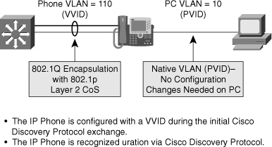
![]() The Voice VLAN feature on Cisco switches uses special nomenclature. The switch refers to the native VLAN for data traffic as the port VLAN ID (PVID) and the Voice VLAN for voice service as the voice VLAN ID (VVID). Moreover, the term Voice VLAN can be represented by the acronym VVLAN, and older Catalyst switches can refer to the Voice VLAN as the auxiliary especially those switches running Cisco CatOS.
The Voice VLAN feature on Cisco switches uses special nomenclature. The switch refers to the native VLAN for data traffic as the port VLAN ID (PVID) and the Voice VLAN for voice service as the voice VLAN ID (VVID). Moreover, the term Voice VLAN can be represented by the acronym VVLAN, and older Catalyst switches can refer to the Voice VLAN as the auxiliary especially those switches running Cisco CatOS.
![]() The following steps highlight the commands to configure and to verify basic functionality of the Voice VLAN feature:
The following steps highlight the commands to configure and to verify basic functionality of the Voice VLAN feature:
![]() In Example 7-4, interface FastEthernet0/24 is configured to set data devices to VLAN 1 by default and VoIP devices to the voice VLAN 700. The switch uses CDP to inform an attached IP Phone of the VLAN. As the port leads to an end device, portfast is enabled. See earlier chapters for more on the Spanning Tree Protocol.
In Example 7-4, interface FastEthernet0/24 is configured to set data devices to VLAN 1 by default and VoIP devices to the voice VLAN 700. The switch uses CDP to inform an attached IP Phone of the VLAN. As the port leads to an end device, portfast is enabled. See earlier chapters for more on the Spanning Tree Protocol.
!
mls qos
!
(text deleted)
!
interface FastEthernet0/24
switchport mode dynamic desirable
switchport voice vlan 700
mls qos trust cos
power inline auto
spanning-tree portfast
!
(text deleted)
!
QoS for Voice Traffic from IP Phones
![]() In a campus QoS implementation, boundaries are defined where the existing QoS values of frames can be accepted (trusted) or altered. Cisco switches apply configurations at these “trust boundaries” to enforce QoS classification and marking as traffic makes its way into the network. At these boundaries, traffic will be optionally allowed to retain its original QoS marking or will optionally have new marking ascribed because of policies associated with its entry point into the network.
In a campus QoS implementation, boundaries are defined where the existing QoS values of frames can be accepted (trusted) or altered. Cisco switches apply configurations at these “trust boundaries” to enforce QoS classification and marking as traffic makes its way into the network. At these boundaries, traffic will be optionally allowed to retain its original QoS marking or will optionally have new marking ascribed because of policies associated with its entry point into the network.
| Note |
|
![]() The term trust from a switch port QoS configuration point-of-view, implies that the switch accepts any DSCP or CoS value received on its port.
The term trust from a switch port QoS configuration point-of-view, implies that the switch accepts any DSCP or CoS value received on its port.
![]() Trust boundaries establish a border for traffic entering the campus network. As traffic traverses the switches of the campus network, it is handled and prioritized according to the marks received or trusted when the traffic originally entered the network at the trust boundary.
Trust boundaries establish a border for traffic entering the campus network. As traffic traverses the switches of the campus network, it is handled and prioritized according to the marks received or trusted when the traffic originally entered the network at the trust boundary.
![]() At the trust boundary device, QoS values are trusted if they are considered to accurately represent the type of traffic and precedence processing that the traffic should receive as it enters the campus network.
At the trust boundary device, QoS values are trusted if they are considered to accurately represent the type of traffic and precedence processing that the traffic should receive as it enters the campus network.
![]() If untrusted, the traffic is marked with a new QoS value that is appropriate for the policy that is in place at the point where the traffic enters the campus network. Ideally, the trust boundary exists at the first switch that receives traffic from a device or IP Phone. It is also acceptable to establish the trust boundary as all the traffic from an access switch that enters a distribution layer switch port.
If untrusted, the traffic is marked with a new QoS value that is appropriate for the policy that is in place at the point where the traffic enters the campus network. Ideally, the trust boundary exists at the first switch that receives traffic from a device or IP Phone. It is also acceptable to establish the trust boundary as all the traffic from an access switch that enters a distribution layer switch port.
![]() To enable QoS on a switch, some models of Cisco switches just require you to enter any QoS command; some others need to have QoS support globally enabled through the command mls qos. Refer to the Cisco configuration guide for your specific model of the Cisco switch for more information.
To enable QoS on a switch, some models of Cisco switches just require you to enter any QoS command; some others need to have QoS support globally enabled through the command mls qos. Refer to the Cisco configuration guide for your specific model of the Cisco switch for more information.
![]() In the Example 7-4, QoS support is first enabled globally. The CoS values received from the phone are trusted and not altered.
In the Example 7-4, QoS support is first enabled globally. The CoS values received from the phone are trusted and not altered.
![]() You can use the show mls qos family of commands to display QoS configuration on specific models of Cisco switches. Check the product configuration guides for your specific switch.
You can use the show mls qos family of commands to display QoS configuration on specific models of Cisco switches. Check the product configuration guides for your specific switch.
Power over Ethernet
![]() All VoIP-enabled devices need a source of power. When these devices are handheld or mobile devices, the source of energy is usually a battery. Desktop or wall-mount VoIP phones can be connected to an A/C adapter for power.
All VoIP-enabled devices need a source of power. When these devices are handheld or mobile devices, the source of energy is usually a battery. Desktop or wall-mount VoIP phones can be connected to an A/C adapter for power.
![]() Although power is easily available in an office environment, using one AC/DC socket per VoIP device might be considered as a waste of physical resources. Because the phone has a cable connection to the Ethernet switch, a logical solution is to use this cable to provide power and connectivity.
Although power is easily available in an office environment, using one AC/DC socket per VoIP device might be considered as a waste of physical resources. Because the phone has a cable connection to the Ethernet switch, a logical solution is to use this cable to provide power and connectivity.
![]() This setting, called Power over Ethernet (PoE), implies that the power comes through the Ethernet cable. The source of this power can be the switch itself, if the switch supports the PoE feature.
This setting, called Power over Ethernet (PoE), implies that the power comes through the Ethernet cable. The source of this power can be the switch itself, if the switch supports the PoE feature.
![]() If the switch cannot provide power, it is often possible to install an intermediate device between the switch and the VoIP phone. This device will receive power from a power outlet and will connect to the switch with another cable. It connects to the port to which the phone is supposed to connect. A third cable runs from this intermediate device to the phone, providing power along with data transmission to and from the switch. This device is called a power injector.
If the switch cannot provide power, it is often possible to install an intermediate device between the switch and the VoIP phone. This device will receive power from a power outlet and will connect to the switch with another cable. It connects to the port to which the phone is supposed to connect. A third cable runs from this intermediate device to the phone, providing power along with data transmission to and from the switch. This device is called a power injector.
![]() To decrease the cost and complexity of the installation, powering the devices directly from the switch is often seen as the best solution.
To decrease the cost and complexity of the installation, powering the devices directly from the switch is often seen as the best solution.
![]() A great advantage of PoE is that no electrician is required. Anyone qualified to run Category 5e cable can install the cabling required to power PoE enabled devices. The standard Category 5e cable requirements still apply (maximum 328 feet or 100 meters).
A great advantage of PoE is that no electrician is required. Anyone qualified to run Category 5e cable can install the cabling required to power PoE enabled devices. The standard Category 5e cable requirements still apply (maximum 328 feet or 100 meters).
![]() Two common PoE methods exist: the Cisco inline power and the IEEE 802.3af standard. Cisco inline power is prestandard because the IEEE 802.3 standard did not include specifications for PoE. The 802.3af task force amended this omission and a standard was realized in 2003. Cisco was actively involved in the 802.3af taskforce and support of the IEEE inline power standard. One of the main differences is that 802.3af uses a power detection mechanism that detects if the connected device needs power. Standard ratification of 802.3af occurred on September 11, 2009.
Two common PoE methods exist: the Cisco inline power and the IEEE 802.3af standard. Cisco inline power is prestandard because the IEEE 802.3 standard did not include specifications for PoE. The 802.3af task force amended this omission and a standard was realized in 2003. Cisco was actively involved in the 802.3af taskforce and support of the IEEE inline power standard. One of the main differences is that 802.3af uses a power detection mechanism that detects if the connected device needs power. Standard ratification of 802.3af occurred on September 11, 2009.
![]() New Cisco devices (switches, access points) support both methods for backward compatibility. No specific configuration is required to choose the Cisco prestandard or the 802.3af standard. The IEEE 803.2af standard will be enhanced with a new standard 802.3at, which will provide more power in future.
New Cisco devices (switches, access points) support both methods for backward compatibility. No specific configuration is required to choose the Cisco prestandard or the 802.3af standard. The IEEE 803.2af standard will be enhanced with a new standard 802.3at, which will provide more power in future.
| Note |
|
![]() An interim solution from Cisco called enhanced PoE provides up to 20W of power with the E-series switches. Although most devices can use power supplied by a standard 802.3af source, some new devices require more power.
An interim solution from Cisco called enhanced PoE provides up to 20W of power with the E-series switches. Although most devices can use power supplied by a standard 802.3af source, some new devices require more power.
![]() Power requirements for access-points are specific. Cisco IP Phones use less than 15 Watts and can be powered from a standard 802.3af switch.
Power requirements for access-points are specific. Cisco IP Phones use less than 15 Watts and can be powered from a standard 802.3af switch.
![]() PoE support is done at the port level. The command power inline auto is sufficient to enable PoE and autodetection of power requirements. A device not needing any PoE can still be connected to that port: Power is supplied only if the device requires it. The amount of power supplied will be automatically detected. You still have to plan for the overall power consumed by all the devices connected to the PoE switch.
PoE support is done at the port level. The command power inline auto is sufficient to enable PoE and autodetection of power requirements. A device not needing any PoE can still be connected to that port: Power is supplied only if the device requires it. The amount of power supplied will be automatically detected. You still have to plan for the overall power consumed by all the devices connected to the PoE switch.
![]() The command show power inline, as shown in Example 7-5, displays the configuration and statistics about the used power drawn by connected powered devices and the capacity of the power supply.
The command show power inline, as shown in Example 7-5, displays the configuration and statistics about the used power drawn by connected powered devices and the capacity of the power supply.
Available:665(w) Used:663(w) Remaining:2(w)
Interface Admin Oper Power Device Class
(Watts)
---- ---- ---- ---- ---- ---- ---- ---- ---- ---- ---- ----
Fa4/1 auto on 5.0 Cisco IP Phone 7960 n/a
Interface AdminPowerMax AdminAllocation
(milli-watts) (milli-watts)
---- ---- ---- ---- ---- ---- ---- ---- ---- --
Fa4/1 15400 15400
Switch#
![]() Every switch has a dedicated maximum amount of power available for PoE. The power used by each PoE port is deducted from the total available power. The power used by each device is dynamically learned from via CDP. This feature allows for optimization of the actual power consumption, as a PoE device does not always consume the maximum amount of power it needs. For example, an IP Phone classified as 15 Watts might use up to 15 Watts when fully utilized, but use only 6 or 7 Watts while it is on hook.
Every switch has a dedicated maximum amount of power available for PoE. The power used by each PoE port is deducted from the total available power. The power used by each device is dynamically learned from via CDP. This feature allows for optimization of the actual power consumption, as a PoE device does not always consume the maximum amount of power it needs. For example, an IP Phone classified as 15 Watts might use up to 15 Watts when fully utilized, but use only 6 or 7 Watts while it is on hook.
| Note |
|
![]() Nevertheless, if a phone is said to require up to 15 Watts, if the remaining power at the switch level is less than 15 Watts, the phone will not get power at all. Notice that not all switches have 15 Watts of power available for all ports. Some switches have all ports being PoE with 15 Watts each (which is the maximum possible power under the 802.3af protocol); some others have only a few ports supporting PoE, and not all of them offer 15 Watts.
Nevertheless, if a phone is said to require up to 15 Watts, if the remaining power at the switch level is less than 15 Watts, the phone will not get power at all. Notice that not all switches have 15 Watts of power available for all ports. Some switches have all ports being PoE with 15 Watts each (which is the maximum possible power under the 802.3af protocol); some others have only a few ports supporting PoE, and not all of them offer 15 Watts.
![]() When a VoIP device obtains power and accesses the network at Layer 2, it needs to obtain an IP address. Just like any other client device, it can obtain this IP address through a DHCP server.
When a VoIP device obtains power and accesses the network at Layer 2, it needs to obtain an IP address. Just like any other client device, it can obtain this IP address through a DHCP server.
Additional Network Requirements for VoIP
![]() One additional requirement of Cisco IP phones is that they also need to download a specific configuration file that can provide them with specific voice information, such as Codec to use, location of the CUCM or CUCME. This configuration file is downloaded using TFTP. The TFTP server IP address can be configured manually into each Cisco IP Phone, or provided as a DHCP option 150 (TFTP server address).
One additional requirement of Cisco IP phones is that they also need to download a specific configuration file that can provide them with specific voice information, such as Codec to use, location of the CUCM or CUCME. This configuration file is downloaded using TFTP. The TFTP server IP address can be configured manually into each Cisco IP Phone, or provided as a DHCP option 150 (TFTP server address).
![]() The VoIP device then downloads its configuration file from the TFTP server and also verifies whether a newer firmware is available. It then tries to reach a CUCM or CUCME server. This server’s IP address can be provided within the configuration file or can be provisioned through DNS. Many deployments tend to use the CUCM or CUCME as the TFTP server to simplify the overall procedure, thus removing the need for an external TFTP server and DNS resolution.
The VoIP device then downloads its configuration file from the TFTP server and also verifies whether a newer firmware is available. It then tries to reach a CUCM or CUCME server. This server’s IP address can be provided within the configuration file or can be provisioned through DNS. Many deployments tend to use the CUCM or CUCME as the TFTP server to simplify the overall procedure, thus removing the need for an external TFTP server and DNS resolution.
![]() When the phone contacts the CUCM or CUCME, it registers to it, obtains its line extension number, and is ready to place or receive calls.
When the phone contacts the CUCM or CUCME, it registers to it, obtains its line extension number, and is ready to place or receive calls.
![]() To test voice implementation, it is recommended to work through the logical boot process of the phone.
To test voice implementation, it is recommended to work through the logical boot process of the phone.
![]() Like any other networking device, a phone upon boot up needs to receive power. It will then receive an IP address. If the IP address is received via DHCP, the DHCP option should also provide the CUCM or CUCME IP address. The phone downloads its configuration and firmware from the voice server, before registering, obtaining a phone extension and is ready to place a call.
Like any other networking device, a phone upon boot up needs to receive power. It will then receive an IP address. If the IP address is received via DHCP, the DHCP option should also provide the CUCM or CUCME IP address. The phone downloads its configuration and firmware from the voice server, before registering, obtaining a phone extension and is ready to place a call.
![]() When testing a new VoIP implementation, a logical testing scheme is to check that the phone receives power; then an IP address actually tries to get to the CUCM or CUCME, and registers there. When all these steps are completed, the phone can place and receive calls.
When testing a new VoIP implementation, a logical testing scheme is to check that the phone receives power; then an IP address actually tries to get to the CUCM or CUCME, and registers there. When all these steps are completed, the phone can place and receive calls.
Preparing the Campus Infrastructure to Support Video
![]() As previously discussed, video is no longer in its infancy, but it’s still a growing and evolving technology yielding tremendous benefits to the enterprise in forms of collaboration. When deploying this technology in the campus, several switch configurations need to be considered. This section reviews video components and applications and discusses a few best practices for storage.
As previously discussed, video is no longer in its infancy, but it’s still a growing and evolving technology yielding tremendous benefits to the enterprise in forms of collaboration. When deploying this technology in the campus, several switch configurations need to be considered. This section reviews video components and applications and discusses a few best practices for storage.
Video Components
![]() Video components were covered in the planning section on video in this chapter. As a short review, the following list highlights the most common video applications found deployed in campus networks:
Video components were covered in the planning section on video in this chapter. As a short review, the following list highlights the most common video applications found deployed in campus networks:
- Peer-to-peer video
- TelePresence
- IP surveillance
- Digital media systems
![]() IP surveillance and digital media systems were not covered as video applications in the planning section. IP surveillance systems record video for security purposes. Traditional surveillance security companies now offer IP solutions, and Cisco offers its own solution as well. IP surveillance solutions enable for features not typical with traditional video surveillance. These features include digital video archiving, on-demand viewing, and e-mail and web video updates.
IP surveillance and digital media systems were not covered as video applications in the planning section. IP surveillance systems record video for security purposes. Traditional surveillance security companies now offer IP solutions, and Cisco offers its own solution as well. IP surveillance solutions enable for features not typical with traditional video surveillance. These features include digital video archiving, on-demand viewing, and e-mail and web video updates.
![]() Moreover, digital media systems offer video as a means of communication. Cisco currently offers a digital media system that offers a full set of features to include social video, digital signage, and IPTV systems. The Cisco digital media system is geared for learning, communication, and collaboration.
Moreover, digital media systems offer video as a means of communication. Cisco currently offers a digital media system that offers a full set of features to include social video, digital signage, and IPTV systems. The Cisco digital media system is geared for learning, communication, and collaboration.
![]() As with peer-to-peer video and TelePresence, IP surveillance and digital media systems bandwidth and availability requirements must be taken into account when designing a campus network.
As with peer-to-peer video and TelePresence, IP surveillance and digital media systems bandwidth and availability requirements must be taken into account when designing a campus network.
Configuring Switches to Support Video
![]() Cisco switches do not require any specific or standard configuration to support video. However, PoE is optional for some models of IP surveillance cameras, and QoS features might be necessary to guarantee bandwidth or solve traffic congestion issues caused by high-bandwidth applications such as TelePresence. The recommend best practice goals for jitter, latency, and packet loss of TelePresence or any real-time (interactive) video applications is as follows:
Cisco switches do not require any specific or standard configuration to support video. However, PoE is optional for some models of IP surveillance cameras, and QoS features might be necessary to guarantee bandwidth or solve traffic congestion issues caused by high-bandwidth applications such as TelePresence. The recommend best practice goals for jitter, latency, and packet loss of TelePresence or any real-time (interactive) video applications is as follows:
- Packet loss of less than 0.5 percent
- Jitter of less than 10 ms one-way
- Latency of less than 150 ms one-way
![]() As a best practice for achieving these goals for TelePresence or other high-bandwidth video applications, consider implementing the QoS configurations:
As a best practice for achieving these goals for TelePresence or other high-bandwidth video applications, consider implementing the QoS configurations:
- Classify and mark traffic by using DSCP as close to its edge as possible, preferably on the first-hop access layer switch. If a host is trusted, allow the trusted hosts to mark their own traffic.
- Trust QoS on each inter-switch and switch to router links to preserve marking as frames travel through the network. See RFC4594 for more information.
- Limit the amount of real-time voice and video traffic to 33 percent of link capacity; if higher than this, TelePresence data might starve out other applications resulting in slow or erratic performance of data applications.
- Reserve at least 25 percent of link bandwidth for the best-effort data traffic.
- Deploy a 1 percent Scavenger class to help ensure that unruly applications do not dominate the best-effort data class.
- Use DSCP-based Weighted Random Early Detection (WRED) queuing on all TCP flows, wherever possible.
![]() The preceding list is only a high-level synopsis of a few best-practice guidelines for TelePresence and other high-bandwidth applications. However, these applications require a detailed analysis end-to-end of the entire enterprise network for preparing any QoS implementation. As such, the context of QoS needed for TelePresence is outside the scope of this book. Review additional documentation on Cisco.com or consult with specialist prior to implementing TelePresence in a campus network.
The preceding list is only a high-level synopsis of a few best-practice guidelines for TelePresence and other high-bandwidth applications. However, these applications require a detailed analysis end-to-end of the entire enterprise network for preparing any QoS implementation. As such, the context of QoS needed for TelePresence is outside the scope of this book. Review additional documentation on Cisco.com or consult with specialist prior to implementing TelePresence in a campus network.
Summary
![]() This chapter presented topics pertaining to implementing wireless, voice, and video into the campus network. As evident by the amount of material presented and the brevity that some of the topics covered, you should consult specialist, experts, and persons experienced with these technologies before planning an implementation. Switching is a broad enough topic without the inclusion of these advance technologies.
This chapter presented topics pertaining to implementing wireless, voice, and video into the campus network. As evident by the amount of material presented and the brevity that some of the topics covered, you should consult specialist, experts, and persons experienced with these technologies before planning an implementation. Switching is a broad enough topic without the inclusion of these advance technologies.
![]() Nevertheless, the follow list summarizes several key points for wireless, voice, and video from this chapter:
Nevertheless, the follow list summarizes several key points for wireless, voice, and video from this chapter:
- When planning for a wireless deployment, carefully consider the standalone WLAN solution and the controller-based solution. For networks of more than a few access points, the best practice is to use a controller-based solution.
- When preparing for a wireless deployment, verify your switch port configuration as a truck port. Access points optionally support trunking and carry multiple VLANs. Wireless clients can map to different SSIDs, which it turn might be carried on different VLANs.
- When planning for a voice implementation in the campus network, best-practice guides recommend the use of QoS and the use of a separate VLAN for voice traffic. Power over Ethernet (PoE) is another option to power Cisco IP Phones without the use of an AC/DC adapter.
- When preparing for the voice implementation, ensure that you configure QoS as close to the edge port as possible. Best practice guides recommend trusting DSCP or CoS of frames entering the switch.
- When planning for a video implementation, denote whether the video application is real-time video or on-demand video. Real-time video requires low latency and send traffic in bursts at high bandwidth.
- When preparing for a video implementation such as TelePresence, consult with a specialist or expert to ensure the campus network meets all the requirements in terms of bandwidth, QoS, and such.
3 comments
• I very much enjoyed this article. Nice article thanks for given this information. I hope it useful to many Peopledata since Online Training india
• Nice and good article. It is very useful for me to learn and understand easily. Thanks for sharing your valuable information and time. Please keep updatingAzure Online Training Hyderabad
thank you so much such information.
Microsoft Windows Azure Training | Online Course | Certification in chennai | Microsoft Windows Azure Training | Online Course | Certification in bangalore | Microsoft Windows Azure Training | Online Course | Certification in hyderabad | Microsoft Windows Azure Training | Online Course | Certification in pune
Post a Comment