Understanding QoS
![]() Cisco switches provide a wide range of QoS features that address the needs of voice, video, and data applications sharing a single campus network. Cisco QoS technology enables you to implement complex networks that predictably manage services to a variety of networked applications and traffic types including voice and video.
Cisco switches provide a wide range of QoS features that address the needs of voice, video, and data applications sharing a single campus network. Cisco QoS technology enables you to implement complex networks that predictably manage services to a variety of networked applications and traffic types including voice and video.
![]() Using QoS features and services, you can design and implement networks that conform to either the Internet Engineering Task Force (IETF) integrated services (IntServ) model or the differentiated services (DiffServ) model. Cisco switches provide for differentiated services using QoS features, such as classification and marking, traffic conditioning, congestion avoidance, and congestion management.
Using QoS features and services, you can design and implement networks that conform to either the Internet Engineering Task Force (IETF) integrated services (IntServ) model or the differentiated services (DiffServ) model. Cisco switches provide for differentiated services using QoS features, such as classification and marking, traffic conditioning, congestion avoidance, and congestion management.
![]() For a campus network design, the role of QoS in the campus network is to provide the following characteristics:
For a campus network design, the role of QoS in the campus network is to provide the following characteristics:
-
 Control over resources: You have control over which network resources (bandwidth, equipment, wide-area facilities, and so on) are used. For example, critical traffic, such as voice, video, and data, might consume a link with each type of traffic competing for link bandwidth. QoS helps to control the use of the resources (for example, dropping low-priority packets), thereby preventing low-priority traffic from monopolizing link bandwidth and affecting high-priority traffic, such as voice traffic.
 -
 More efficient use of network resources: By using network analysis management and accounting tools, you can determine how traffic is handled and which traffic experiences delivery issues. If traffic is not handled optimally, you can use QoS features to adjust the switch behavior for specific traffic flows.
 -
 Tailored services: The control and visibility provided by QoS enables Internet service providers to offer carefully tailored grades of service differentiation to their customers. For example, an internal enterprise network application can offer different service for an ordering website that receives 3000 to 4000 hits per day, compared to a human resources website that receives only 200 to 300 hits per day.
 -
 Coexistence of mission-critical applications: QoS technologies make certain that mission-critical applications that are most important to a business receive the most efficient use of the network. Time-sensitive voice and video applications require bandwidth and minimized delays, whereas other applications on a link receive fair service without interfering with mission-critical traffic.
![]() QoS provides solutions for its defined roles by managing network congestion. Congestion greatly affects the network availability and stability problem areas, but congestion is not the sole factor for these problem areas. All networks, including those without congestion, might experience the following three network availability and stability problems:
QoS provides solutions for its defined roles by managing network congestion. Congestion greatly affects the network availability and stability problem areas, but congestion is not the sole factor for these problem areas. All networks, including those without congestion, might experience the following three network availability and stability problems:
-
 Delay (or latency): The amount of time it takes for a packet to reach a destination
 -
 Delay variation (or jitter): The change in inter-packet latency within a stream over time
 -
 Packet loss: The measure of lost packets between any given source and destination
![]() Latency, jitter, and packet loss can occur even in multilayer switched networks with adequate bandwidth. As a result, each multilayer switched network design needs to plan for QoS. A well-designed QoS implementation aids in preventing packet loss while minimizing latency and jitter.
Latency, jitter, and packet loss can occur even in multilayer switched networks with adequate bandwidth. As a result, each multilayer switched network design needs to plan for QoS. A well-designed QoS implementation aids in preventing packet loss while minimizing latency and jitter.
 QoS Service Models
![]() As discussed in the previous section, the two QoS architectures used in IP networks when designing a QoS solution are the IntServ and DiffServ models. The QoS service models differ by two characteristics: how the models enable applications to send data, and how networks attempt to deliver the respective data with a specified level of service.
As discussed in the previous section, the two QoS architectures used in IP networks when designing a QoS solution are the IntServ and DiffServ models. The QoS service models differ by two characteristics: how the models enable applications to send data, and how networks attempt to deliver the respective data with a specified level of service.
![]() A third method of service is the best-effort service, which is essentially the default behavior of the network device without QoS. In summary, the following list restates these three basic levels of service for QoS:
A third method of service is the best-effort service, which is essentially the default behavior of the network device without QoS. In summary, the following list restates these three basic levels of service for QoS:
-
 Best-effort service: The standard form of connectivity without guarantees. This type of service, in reference to Catalyst switches, uses first-in, first-out (FIFO) queues, which simply transmit packets as they arrive in a queue with no preferential treatment.
 -
 Integrated services: IntServ, also known as hard QoS, is a reservation of services. In other words, the IntServ model implies that traffic flows are reserved explicitly by all intermediate systems and resources.
 -
 Differentiated services: DiffServ, also known as soft QoS, is class-based, in which some classes of traffic receive preferential handling over other traffic classes. Differentiated services use statistical preferences, not a hard guarantee such as integrated services. In other words, DiffServ categorizes traffic and then sorts it into queues of various efficiencies.
![]() From the perspective of campus network design, differentiated service is the method used, because most switches support DiffServ and not IntServ.
From the perspective of campus network design, differentiated service is the method used, because most switches support DiffServ and not IntServ.
![]() Figure 7-13 illustrates the queuing components of a Cisco switch. These components match to the building blocks of QoS in a campus network. The figure illustrates the classification that occurs on ingress packets. After the switch classifies a packet, it determines whether to place the packet into a queue or drop the packet. Queuing mechanisms drop packets only if the corresponding queue is full without the use of congestion avoidance.
Figure 7-13 illustrates the queuing components of a Cisco switch. These components match to the building blocks of QoS in a campus network. The figure illustrates the classification that occurs on ingress packets. After the switch classifies a packet, it determines whether to place the packet into a queue or drop the packet. Queuing mechanisms drop packets only if the corresponding queue is full without the use of congestion avoidance.
![]() As illustrated in Figure 7-13, QoS in the campus network has the following main components:
As illustrated in Figure 7-13, QoS in the campus network has the following main components:
![]() Later sections in this chapter discuss these QoS components and how they apply to the campus network. The next section discusses a side topic related to configuring QoS that needs planning consideration.
Later sections in this chapter discuss these QoS components and how they apply to the campus network. The next section discusses a side topic related to configuring QoS that needs planning consideration.
 AutoQoS
![]() As a side note to the QoS components, Cisco AutoQoS is a product feature that enables customers to deploy QoS features for converged IP telephony and data networks much more quickly and efficiently. Cisco AutoQoS generates traffic classes and policy map CLI templates. Cisco AutoQoS simplifies the definition of traffic classes and the creation and configuration of traffic policies. As a result, in-depth knowledge of the underlying technologies, service policies, link efficiency mechanisms, and Cisco QoS best-practice recommendations for voice requirements is not required to configure Cisco AutoQoS.
As a side note to the QoS components, Cisco AutoQoS is a product feature that enables customers to deploy QoS features for converged IP telephony and data networks much more quickly and efficiently. Cisco AutoQoS generates traffic classes and policy map CLI templates. Cisco AutoQoS simplifies the definition of traffic classes and the creation and configuration of traffic policies. As a result, in-depth knowledge of the underlying technologies, service policies, link efficiency mechanisms, and Cisco QoS best-practice recommendations for voice requirements is not required to configure Cisco AutoQoS.
![]() Cisco AutoQoS can be extremely beneficial for these planning scenarios:
Cisco AutoQoS can be extremely beneficial for these planning scenarios:
-
 Small to medium-sized businesses that must deploy IP telephony quickly but lack the experience and staffing to plan and deploy IP QoS services
 -
 Large customer enterprises that need to deploy Cisco telephony solutions on a large scale, while reducing the costs, complexity, and time frame for deployment, and ensuring that the appropriate QoS for voice applications is set in a consistent fashion
 -
 International enterprises or service providers requiring QoS for VoIP where little expertise exists in different regions of the world and where provisioning QoS remotely and across different time zones is difficult
![]() Moreover, Cisco AutoQoS simplifies and shortens the QoS deployment cycle. Cisco AutoQoS aids in the following five major aspects of a successful QoS deployment:
Moreover, Cisco AutoQoS simplifies and shortens the QoS deployment cycle. Cisco AutoQoS aids in the following five major aspects of a successful QoS deployment:
-
 Application classification
 -
 Policy generation
 -
 Configuration
 -
 Monitoring and reporting
 -
 Consistency
![]() Auto-QoS is mentioned in this section because it’s helpful to know that Cisco switches provide a feature to ease planning, preparing, and implementing QoS by abstracting the in-depth technical details of QoS. For a sample configuration of auto-QoS, consult Cisco.com.
Auto-QoS is mentioned in this section because it’s helpful to know that Cisco switches provide a feature to ease planning, preparing, and implementing QoS by abstracting the in-depth technical details of QoS. For a sample configuration of auto-QoS, consult Cisco.com.
![]() The next section begins the discussion of traffic classification and marking.
The next section begins the discussion of traffic classification and marking.
 Traffic Classification and Marking
![]() Traffic classification and marking ultimately determine the QoS applied to a frame. Special bits are used in frames to classify and mark for QoS. There are QoS bits in the frame for both Layer 2 and Layer 3 applications. The next subsection goes into the definition of these bits for classification and marking in more detail.
Traffic classification and marking ultimately determine the QoS applied to a frame. Special bits are used in frames to classify and mark for QoS. There are QoS bits in the frame for both Layer 2 and Layer 3 applications. The next subsection goes into the definition of these bits for classification and marking in more detail.
DSCP, ToS, and CoS
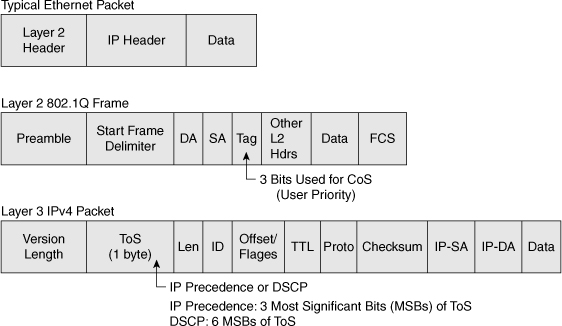
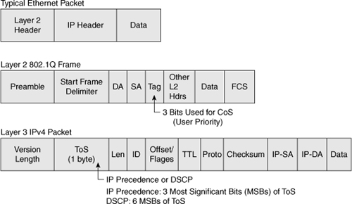
![]() Figure 7-14 illustrates the bits used in Ethernet packets for classification. Network devices use either Layer 2 class of service (CoS) bits of a frame or Layer 3 IP Precedence and Differentiated Services Code Point (DSCP) bits of a packet for classification. At Layer 2, 3 bits are available in 802.1Q frames for classification for up to eight distinct values (levels of service): 0 through 7. These Layer 2 classification bits are referred to as the CoS values. At Layer 3, QoS uses the six most significant ToS bits in the IP header for a DSCP field definition. This DSCP field definition allows for up to 64 distinct values (levels of service)—0 through 63—of classification on IP frames. The last 2 bits represent the Early Congestion Notification (ECN) bits. IP Precedence is only the three most significant bits of the ToS field. As a result, IP Precedence maps to DSCP by using IP Precedence as the three high-order bits and padding the lower-order bits with 0.
Figure 7-14 illustrates the bits used in Ethernet packets for classification. Network devices use either Layer 2 class of service (CoS) bits of a frame or Layer 3 IP Precedence and Differentiated Services Code Point (DSCP) bits of a packet for classification. At Layer 2, 3 bits are available in 802.1Q frames for classification for up to eight distinct values (levels of service): 0 through 7. These Layer 2 classification bits are referred to as the CoS values. At Layer 3, QoS uses the six most significant ToS bits in the IP header for a DSCP field definition. This DSCP field definition allows for up to 64 distinct values (levels of service)—0 through 63—of classification on IP frames. The last 2 bits represent the Early Congestion Notification (ECN) bits. IP Precedence is only the three most significant bits of the ToS field. As a result, IP Precedence maps to DSCP by using IP Precedence as the three high-order bits and padding the lower-order bits with 0.
![]() A practical example of the interoperation between DSCP and IP Precedence is with Cisco IP Phones. Cisco IP Phones mark voice traffic at Layer 3 with a DSCP value of 46 and, consequently, an IP Precedence of 5. Because the first 3 bits of DSCP value 46 in binary is 101 (5), the IP Precedence is 5. As a result, a network device that is only aware of IP Precedence understands the packet priority similarly to a network device that can interpret DSCP. Moreover, Cisco IP Phones mark frames at Layer 2 with a CoS value of 5.
A practical example of the interoperation between DSCP and IP Precedence is with Cisco IP Phones. Cisco IP Phones mark voice traffic at Layer 3 with a DSCP value of 46 and, consequently, an IP Precedence of 5. Because the first 3 bits of DSCP value 46 in binary is 101 (5), the IP Precedence is 5. As a result, a network device that is only aware of IP Precedence understands the packet priority similarly to a network device that can interpret DSCP. Moreover, Cisco IP Phones mark frames at Layer 2 with a CoS value of 5.
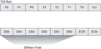
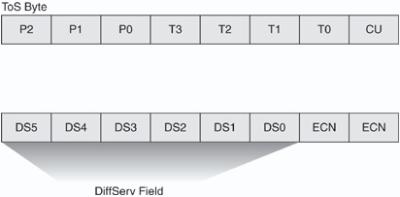
![]() Figure 7-15 illustrates the ToS byte. P2, P1, and P0 make up IP Precedence. T3, T2, T1, and T0 are the ToS bits. When viewing the ToS byte as DSCP, DS5 through DS0 are the DSCP bits. For more information about bits in the IP header that determine classification, refer to RFCs 791, 795, and 1349.
Figure 7-15 illustrates the ToS byte. P2, P1, and P0 make up IP Precedence. T3, T2, T1, and T0 are the ToS bits. When viewing the ToS byte as DSCP, DS5 through DS0 are the DSCP bits. For more information about bits in the IP header that determine classification, refer to RFCs 791, 795, and 1349.
| Note |
|
Classification
![]() Classification distinguishes a frame or packet with a specific priority or predetermined criteria. In the case of Catalyst switches, classification determines the internal DSCP value on frames. Catalyst switches use this internal DSCP value for QoS packet handling, including policing and scheduling as frames traverse the switch.
Classification distinguishes a frame or packet with a specific priority or predetermined criteria. In the case of Catalyst switches, classification determines the internal DSCP value on frames. Catalyst switches use this internal DSCP value for QoS packet handling, including policing and scheduling as frames traverse the switch.
![]() The first task of any QoS policy is to identify traffic that requires classification. With QoS enabled and no other QoS configurations, all Cisco routers and switches treat traffic with a default classification. With respect to DSCP values, the default classification for ingress frames is a DSCP value of 0. The terminology used to describe an interface configured for treating all ingress frames with a DSCP of 0 is untrusted. In review, the following methods of packet classification are available on Cisco switches:
The first task of any QoS policy is to identify traffic that requires classification. With QoS enabled and no other QoS configurations, all Cisco routers and switches treat traffic with a default classification. With respect to DSCP values, the default classification for ingress frames is a DSCP value of 0. The terminology used to describe an interface configured for treating all ingress frames with a DSCP of 0 is untrusted. In review, the following methods of packet classification are available on Cisco switches:
-
 Per-interface manual classification using specific DSCP, IP Precedence, or CoS values
 -
 Per-packet based on access lists
 -
 Network-Based Application Recognition (NBAR)
![]() When planning QoS deployments in campus networks, always apply QoS classification as close to the edge as possible, preferable in the access layer. This methodology allows for end-to-end QoS with ease of management.
When planning QoS deployments in campus networks, always apply QoS classification as close to the edge as possible, preferable in the access layer. This methodology allows for end-to-end QoS with ease of management.
| Note |
|
 Trust Boundaries and Configurations
![]() Trust configurations on Catalyst switches quantify how a frame is handled as it arrives in on a switch. For example, when a switch configured for “trusting DSCP” receives a packet with a DSCP value of 46, the switch accepts the ingress DSCP of the frame and uses the DSCP value of 46 for internal DSCP.
Trust configurations on Catalyst switches quantify how a frame is handled as it arrives in on a switch. For example, when a switch configured for “trusting DSCP” receives a packet with a DSCP value of 46, the switch accepts the ingress DSCP of the frame and uses the DSCP value of 46 for internal DSCP.
![]() Cisco switches support trusting via DSCP, IP Precedence, or CoS values on ingress frames. When trusting CoS or IP Precedence, Cisco switches map an ingress packet’s CoS or IP Precedence to an internal DSCP value. The internal DSCP concept is important because it represents how the packet is handled in the switch. Tables 7-3 and 7-4 illustrate the default mapping tables for CoS-to-DSCP and IP Precedence-to-DSCP, respectively. These mapping tables are configurable.
Cisco switches support trusting via DSCP, IP Precedence, or CoS values on ingress frames. When trusting CoS or IP Precedence, Cisco switches map an ingress packet’s CoS or IP Precedence to an internal DSCP value. The internal DSCP concept is important because it represents how the packet is handled in the switch. Tables 7-3 and 7-4 illustrate the default mapping tables for CoS-to-DSCP and IP Precedence-to-DSCP, respectively. These mapping tables are configurable.
|
|
|
|
|
|
|
|
|
|
|
|
|
|
|
|
|
|
|
|
|
|
|
|
|
|
|
|
|
|
|
|
|
|
|
|
|
|
|
|
![]() Figure 7-16 illustrates the Catalyst QoS trust concept using port trusting. When the Catalyst switch trusts CoS on ingress packets on a port basis, the switch maps the ingress value to the respective DSCP value. When the ingress interface QoS configuration is untrusted, the switch uses 0 for the internal DSCP value for all ingress packets.
Figure 7-16 illustrates the Catalyst QoS trust concept using port trusting. When the Catalyst switch trusts CoS on ingress packets on a port basis, the switch maps the ingress value to the respective DSCP value. When the ingress interface QoS configuration is untrusted, the switch uses 0 for the internal DSCP value for all ingress packets.
Marking
![]() Marking in reference to QoS on Catalyst switches refers to changing the DSCP, CoS, or IP Precedence bits on ingress frames. Marking is configurable on a per-interface basis or via a policy map. Marking alters the DSCP value of packets, which in turn affects the internal DSCP. For instance, an example of marking would be to configure a policy map to mark all frames from a video server on a per-interface basis to a DSCP value of 40, resulting in an internal DSCP value of 40 as well.
Marking in reference to QoS on Catalyst switches refers to changing the DSCP, CoS, or IP Precedence bits on ingress frames. Marking is configurable on a per-interface basis or via a policy map. Marking alters the DSCP value of packets, which in turn affects the internal DSCP. For instance, an example of marking would be to configure a policy map to mark all frames from a video server on a per-interface basis to a DSCP value of 40, resulting in an internal DSCP value of 40 as well.
Traffic Shaping and Policing
![]() Both shaping and policing mechanisms control the rate at which traffic flows through a switch. Both mechanisms use classification to differentiate traffic. Nevertheless, there is a fundamental and significant difference between shaping and policing.
Both shaping and policing mechanisms control the rate at which traffic flows through a switch. Both mechanisms use classification to differentiate traffic. Nevertheless, there is a fundamental and significant difference between shaping and policing.
![]() Shaping meters traffic rates and delays (buffers) excessive traffic so that the traffic rates stay within a desired rate limit. As a result, shaping smoothes excessive bursts to produce a steady flow of data. Reducing bursts decreases congestion in downstream routers and switches and, consequently, reduces the number of frames dropped by downstream routers and switches. Because shaping delays traffic, it is not useful for delay-sensitive traffic flows such as voice, video, or storage, but it is useful for typical, bursty TCP flows. Figure 7-17 illustrates an example of traffic shaping applied to TCP data traffic.
Shaping meters traffic rates and delays (buffers) excessive traffic so that the traffic rates stay within a desired rate limit. As a result, shaping smoothes excessive bursts to produce a steady flow of data. Reducing bursts decreases congestion in downstream routers and switches and, consequently, reduces the number of frames dropped by downstream routers and switches. Because shaping delays traffic, it is not useful for delay-sensitive traffic flows such as voice, video, or storage, but it is useful for typical, bursty TCP flows. Figure 7-17 illustrates an example of traffic shaping applied to TCP data traffic.
![]() For more information on which Cisco switches support shaping and configuration guidelines for shaping, consult the Cisco.com website. In campus networks, policing is more commonly used and is widely supported across the Cisco platforms when compared to shaping.
For more information on which Cisco switches support shaping and configuration guidelines for shaping, consult the Cisco.com website. In campus networks, policing is more commonly used and is widely supported across the Cisco platforms when compared to shaping.
Policing
![]() In contrast to shaping, policing takes a specific action for out-of-profile traffic above a specified rate. Policing does not delay or buffer traffic. The action for traffic that exceeds a specified rate is usually drop; however, other actions are permissible, such as trusting and marking.
In contrast to shaping, policing takes a specific action for out-of-profile traffic above a specified rate. Policing does not delay or buffer traffic. The action for traffic that exceeds a specified rate is usually drop; however, other actions are permissible, such as trusting and marking.
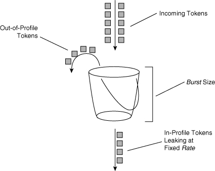
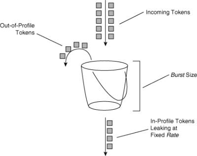
![]() Policing on Cisco switches follows the leaky token bucket algorithm, which allows for bursts of traffic compared to rate limiting. The leaky token bucket algorithm is as effective at handling TCP as it is at handling bursts of UDP flows. Figure 7-18 illustrates the leaky token bucket algorithm.
Policing on Cisco switches follows the leaky token bucket algorithm, which allows for bursts of traffic compared to rate limiting. The leaky token bucket algorithm is as effective at handling TCP as it is at handling bursts of UDP flows. Figure 7-18 illustrates the leaky token bucket algorithm.
![]() When switches apply policing to incoming traffic, they place a number of tokens proportional to the incoming traffic packet sizes into a token bucket in which the number of tokens equals the size of the packet. At a regular interval, the switch removes a defined number of tokens, determined by the configured rate, from the bucket. If the bucket is full and cannot accommodate an ingress packet, the switch determines that the packet is out of profile. The switch subsequently drops or marks out-of-profile packets according to the configured policing action, but notice that the number of packets leaving the queue is proportional to the number of tokens in the bucket.
When switches apply policing to incoming traffic, they place a number of tokens proportional to the incoming traffic packet sizes into a token bucket in which the number of tokens equals the size of the packet. At a regular interval, the switch removes a defined number of tokens, determined by the configured rate, from the bucket. If the bucket is full and cannot accommodate an ingress packet, the switch determines that the packet is out of profile. The switch subsequently drops or marks out-of-profile packets according to the configured policing action, but notice that the number of packets leaving the queue is proportional to the number of tokens in the bucket.
![]() Note that the leaky bucket is only a model to explain the differences between policing and shaping.
Note that the leaky bucket is only a model to explain the differences between policing and shaping.
![]() A complete discussion of the leaky token bucket algorithm is outside the scope of this book.
A complete discussion of the leaky token bucket algorithm is outside the scope of this book.
![]() The next sections discuss congestion management and congestion avoidance. Congestion management is the key feature of QoS.
The next sections discuss congestion management and congestion avoidance. Congestion management is the key feature of QoS.
 Congestion Management
![]() Cisco switches use multiple egress queues for application of the congestion-management and congestion-avoidance QoS features. Both congestion management and congestion avoidance are a per-queue feature. For example, congestion-avoidance threshold configurations are per queue, and each queue might have its own configuration for congestion management and avoidance.
Cisco switches use multiple egress queues for application of the congestion-management and congestion-avoidance QoS features. Both congestion management and congestion avoidance are a per-queue feature. For example, congestion-avoidance threshold configurations are per queue, and each queue might have its own configuration for congestion management and avoidance.
![]() Moreover, classification and marking have little meaning without congestion management. Switches use congestion-management configurations to schedule packets appropriately from output queues when congestion occurs. Cisco switches support a variety of scheduling and queuing algorithms. Each queuing algorithm solves a specific type of network traffic condition.
Moreover, classification and marking have little meaning without congestion management. Switches use congestion-management configurations to schedule packets appropriately from output queues when congestion occurs. Cisco switches support a variety of scheduling and queuing algorithms. Each queuing algorithm solves a specific type of network traffic condition.
![]() Congestion management comprises several queuing mechanisms, including the following:
Congestion management comprises several queuing mechanisms, including the following:
![]() The following subsections discuss these queuing mechanisms in more detail.
The following subsections discuss these queuing mechanisms in more detail.
FIFO Queuing
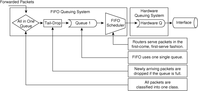
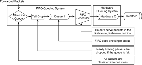
![]() The default method of queuing frames is FIFO queuing, in which the switch places all egress frames into the same queue, regardless of classification. Essentially, FIFO queuing does not use classification, and all packets are treated as if they belong to the same class. The switch schedules packets from the queue for transmission in the order in which they are received. This behavior is the default behavior of Cisco switches without QoS enabled. Figure 7-19 illustrates the behavior of FIFO queuing.
The default method of queuing frames is FIFO queuing, in which the switch places all egress frames into the same queue, regardless of classification. Essentially, FIFO queuing does not use classification, and all packets are treated as if they belong to the same class. The switch schedules packets from the queue for transmission in the order in which they are received. This behavior is the default behavior of Cisco switches without QoS enabled. Figure 7-19 illustrates the behavior of FIFO queuing.
Weighted Round Robin Queuing
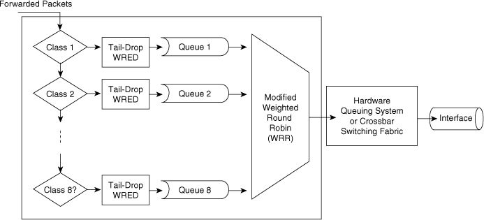
![]() Scheduling packets from egress queues using WRR is a popular and simple method of differentiating service among traffic classes. With WRR, the switch uses a configured weight value for each egress queue. This weight value determines the implied bandwidth of each queue. The higher the weight value, the higher the priority that the switch applies to the egress queue. For example, consider the case of a Cisco switch configured for QoS and WRR. In this example, the Cisco switches use four egress queues. If Queues 1 through 4 are configured with weights 50, 10, 25, and 15, respectively, Queue 1 can utilize 50 percent of the bandwidth when there is congestion. Queues 2 through 4 can utilize 10, 25, and 15 percent of the bandwidth, respectively, when congestion exists. Figure 7-20 illustrates WRR behavior with eight egress queues. Figure 7-20 also illustrates tail-drop and WRED properties, which are explained in later sections.
Scheduling packets from egress queues using WRR is a popular and simple method of differentiating service among traffic classes. With WRR, the switch uses a configured weight value for each egress queue. This weight value determines the implied bandwidth of each queue. The higher the weight value, the higher the priority that the switch applies to the egress queue. For example, consider the case of a Cisco switch configured for QoS and WRR. In this example, the Cisco switches use four egress queues. If Queues 1 through 4 are configured with weights 50, 10, 25, and 15, respectively, Queue 1 can utilize 50 percent of the bandwidth when there is congestion. Queues 2 through 4 can utilize 10, 25, and 15 percent of the bandwidth, respectively, when congestion exists. Figure 7-20 illustrates WRR behavior with eight egress queues. Figure 7-20 also illustrates tail-drop and WRED properties, which are explained in later sections.
![]() The transmit queue ratio determines the way that the buffers are split among the different queues. If you have multiple queues with a priority queue, the configuration requires the same weight on the high-priority WRR queues and for the strict-priority queue. Generally, high-priority queues do not require a large amount of memory for queuing because traffic destined for high-priority queues is delay-sensitive and often low volume. As a result, large queue sizes for high- and strict-priority queues are not necessary. The recommendation is to use memory space for the low-priority queues that generally contain data traffic that is not sensitive to queuing delays. The next section discusses strict-priority queuing with WRR.
The transmit queue ratio determines the way that the buffers are split among the different queues. If you have multiple queues with a priority queue, the configuration requires the same weight on the high-priority WRR queues and for the strict-priority queue. Generally, high-priority queues do not require a large amount of memory for queuing because traffic destined for high-priority queues is delay-sensitive and often low volume. As a result, large queue sizes for high- and strict-priority queues are not necessary. The recommendation is to use memory space for the low-priority queues that generally contain data traffic that is not sensitive to queuing delays. The next section discusses strict-priority queuing with WRR.
![]() Although the queues utilize a percentage of bandwidth, the switch does not actually assign specific bandwidth to each queue when using WRR. The switch uses WRR to schedule packets from egress queues only under congestion. Another noteworthy aspect of WRR is that it does not starve lower-priority queues because the switch services all queues during a finite time period.
Although the queues utilize a percentage of bandwidth, the switch does not actually assign specific bandwidth to each queue when using WRR. The switch uses WRR to schedule packets from egress queues only under congestion. Another noteworthy aspect of WRR is that it does not starve lower-priority queues because the switch services all queues during a finite time period.
Priority Queuing
![]() One method of prioritizing and scheduling frames from egress queues is to use priority queuing. When applying strict priority to one of these queues, the switch schedules frames from that queue if there are frames in that queue before servicing any other queue. Cisco switches ignore WRR scheduling weights for queues configured as priority queues; most Catalyst switches support the designation of a single egress queue as a priority queue.
One method of prioritizing and scheduling frames from egress queues is to use priority queuing. When applying strict priority to one of these queues, the switch schedules frames from that queue if there are frames in that queue before servicing any other queue. Cisco switches ignore WRR scheduling weights for queues configured as priority queues; most Catalyst switches support the designation of a single egress queue as a priority queue.
![]() Priority queuing is useful for voice applications in which voice traffic occupies the priority queue. However, since this type of scheduling can result in queue starvation in the nonpriority queues, the remaining queues are subject to the WRR queuing to avoid this issue.
Priority queuing is useful for voice applications in which voice traffic occupies the priority queue. However, since this type of scheduling can result in queue starvation in the nonpriority queues, the remaining queues are subject to the WRR queuing to avoid this issue.
Custom Queuing
![]() Another method of queuing available on Cisco switches strictly for WAN interfaces is Custom Queuing (CQ), which reserves a percentage of available bandwidth for an interface for each selected traffic type. If a particular type of traffic is not using the reserved bandwidth, other queues and types of traffic might use the remaining bandwidth.
Another method of queuing available on Cisco switches strictly for WAN interfaces is Custom Queuing (CQ), which reserves a percentage of available bandwidth for an interface for each selected traffic type. If a particular type of traffic is not using the reserved bandwidth, other queues and types of traffic might use the remaining bandwidth.
![]() CQ is statically configured and does not provide for automatic adaptation for changing network conditions. In addition, CQ is not recommended on high-speed WAN interfaces; refer to the configuration guides for CQ support on LAN interfaces and configuration details. See the configuration guide for each Cisco switch for supported CQ configurations.
CQ is statically configured and does not provide for automatic adaptation for changing network conditions. In addition, CQ is not recommended on high-speed WAN interfaces; refer to the configuration guides for CQ support on LAN interfaces and configuration details. See the configuration guide for each Cisco switch for supported CQ configurations.
 Congestion Avoidance
![]() Congestion-avoidance techniques monitor network traffic loads in an effort to anticipate and avoid congestion at common network bottleneck points. Switches and routers achieve congestion avoidance through packet dropping using complex algorithms (versus the simple tail-drop algorithm). Campus networks more commonly use congestion-avoidance techniques on WAN interfaces (versus Ethernet interfaces) because of the limited bandwidth of WAN interfaces. However, for Ethernet interfaces of considerable congestion, congestion avoidance is useful.
Congestion-avoidance techniques monitor network traffic loads in an effort to anticipate and avoid congestion at common network bottleneck points. Switches and routers achieve congestion avoidance through packet dropping using complex algorithms (versus the simple tail-drop algorithm). Campus networks more commonly use congestion-avoidance techniques on WAN interfaces (versus Ethernet interfaces) because of the limited bandwidth of WAN interfaces. However, for Ethernet interfaces of considerable congestion, congestion avoidance is useful.
Tail Drop
![]() When an interface of a router or switch cannot transmit a packet immediately because of congestion, the router or switch queues the packet. The router or switch eventually transmits the packet from the queue. If the arrival rate of packets for transmission on an interface exceeds the router’s or switch’s capability to buffer the traffic, the router or switch simply drops the packets. This behavior is called tail drop because all packets for transmission attempting to enter an egress queue are dropped until there is space in the queue for another packet. Tail drop is the default behavior on Cisco switch interfaces.
When an interface of a router or switch cannot transmit a packet immediately because of congestion, the router or switch queues the packet. The router or switch eventually transmits the packet from the queue. If the arrival rate of packets for transmission on an interface exceeds the router’s or switch’s capability to buffer the traffic, the router or switch simply drops the packets. This behavior is called tail drop because all packets for transmission attempting to enter an egress queue are dropped until there is space in the queue for another packet. Tail drop is the default behavior on Cisco switch interfaces.
![]() For environments with a large number of TCP flows or flows where arbitrary packet drops are detrimental, tail drop is not the best approach to dropping frames. Moreover, tail drop has these shortcomings with respect to TCP flows:
For environments with a large number of TCP flows or flows where arbitrary packet drops are detrimental, tail drop is not the best approach to dropping frames. Moreover, tail drop has these shortcomings with respect to TCP flows:
-
 The dropping of frames usually affects ongoing TCP sessions. Arbitrary dropping of frames with a TCP session results in concurrent TCP sessions simultaneously backing off and restarting, yielding a “saw-tooth” effect. As a result, inefficient link utilization occurs at the congestion point (TCP global synchronization).
 -
 Aggressive TCP flows might seize all space in output queues over normal TCP flow as a result of tail drop.
 -
 Excessive queuing of packets in the output queues at the point of congestion results in delay and jitter as packets await transmission.
 -
 No differentiated drop mechanism exists; premium traffic is dropped in the same manner as best-effort traffic.
 -
 Even in the event of a single TCP stream across an interface, the presence of other non-TCP traffic might congest the interface. In this scenario, the feedback to the TCP protocol is poor; as a result, TCP cannot adapt properly to the congested network.
Weighted Random Early Detection
![]() WRED is a congestion-avoidance mechanism that is useful for backbone speeds. WRED attempts to avoid congestion by randomly dropping packets with a certain classification when output buffers reach a specific threshold.
WRED is a congestion-avoidance mechanism that is useful for backbone speeds. WRED attempts to avoid congestion by randomly dropping packets with a certain classification when output buffers reach a specific threshold.
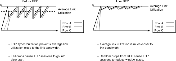
![]() Figure 7-21 illustrates the behavior of TCP with and without RED. As illustrated in the diagram, RED smoothes TCP sessions because it randomly drops packets, which ultimately reduces TCP windows. Without RED, TCP flows go through a slow start simultaneously. The end result of RED is better link utilization.
Figure 7-21 illustrates the behavior of TCP with and without RED. As illustrated in the diagram, RED smoothes TCP sessions because it randomly drops packets, which ultimately reduces TCP windows. Without RED, TCP flows go through a slow start simultaneously. The end result of RED is better link utilization.
![]() RED randomly drops packets at configured threshold values (percentage full) of output buffers. As more packets fill the output queues, the switch randomly drops frames in an attempt to avoid congestion without the saw-tooth TCP problem. RED works only when the output queue is not full; when the output queue is full, the switch tail-drops any additional packets that attempt to occupy the output queue. However, the probability of dropping a packet rises as the output queue begins to fill above the RED threshold.
RED randomly drops packets at configured threshold values (percentage full) of output buffers. As more packets fill the output queues, the switch randomly drops frames in an attempt to avoid congestion without the saw-tooth TCP problem. RED works only when the output queue is not full; when the output queue is full, the switch tail-drops any additional packets that attempt to occupy the output queue. However, the probability of dropping a packet rises as the output queue begins to fill above the RED threshold.
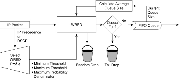
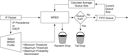
![]() RED works well for TCP flows but not for other types of traffic, such as UDP flows and voice traffic. WRED is similar to RED except that WRED takes into account classification of frames. For example, for a single output queue, a switch configuration might consist of a WRED threshold of 50 percent for all best-effort traffic for DSCP values up to 20, and 80 percent for all traffic with a DSCP value between 20 and 31. In this example, the switch drops existing packets in the output queue with a DSCP of 0 to 20 when the queue’s threshold reaches 50 percent. If the queue continues to fill to the 80 percent threshold, the switch then begins to drop existing packets with DSCP values above 20. If the output queue is full even with WRED configured, the switch tail-drops any additional packets that attempt to occupy the output queue. The end result of the WRED configuration is that the switch is less likely to drop packets with higher priorities (higher DSCP value). Figure 7-22 illustrates the WRED algorithm pictorially.
RED works well for TCP flows but not for other types of traffic, such as UDP flows and voice traffic. WRED is similar to RED except that WRED takes into account classification of frames. For example, for a single output queue, a switch configuration might consist of a WRED threshold of 50 percent for all best-effort traffic for DSCP values up to 20, and 80 percent for all traffic with a DSCP value between 20 and 31. In this example, the switch drops existing packets in the output queue with a DSCP of 0 to 20 when the queue’s threshold reaches 50 percent. If the queue continues to fill to the 80 percent threshold, the switch then begins to drop existing packets with DSCP values above 20. If the output queue is full even with WRED configured, the switch tail-drops any additional packets that attempt to occupy the output queue. The end result of the WRED configuration is that the switch is less likely to drop packets with higher priorities (higher DSCP value). Figure 7-22 illustrates the WRED algorithm pictorially.
![]() On most Cisco switches, WRED is configurable per queue. Nevertheless, it is possible to use WRR and WRED together. A best-practice recommendation is to designate a strict-priority queue for high-priority traffic using WRR and use WRED for congestion avoidance with the remaining queues designated for data traffic.
On most Cisco switches, WRED is configurable per queue. Nevertheless, it is possible to use WRR and WRED together. A best-practice recommendation is to designate a strict-priority queue for high-priority traffic using WRR and use WRED for congestion avoidance with the remaining queues designated for data traffic.
![]() For planning for the campus network, consider using WRED on highly congested interfaces, particularly WAN interfaces that interconnect data centers.
For planning for the campus network, consider using WRED on highly congested interfaces, particularly WAN interfaces that interconnect data centers.




0 comments
Post a Comment