![]() This chapter focuses on advanced services in the network to include wireless, voice, and video. The chapter is organized into sections where planning information is presented for wireless, voice, and video, followed by introductions to QoS and multicast, and ending with information on preparing and implementing wireless, voice, and video. QoS and multicast are introduced because QoS is a requirement for voice and video in the campus network, while multicast is used by several video applications.
This chapter focuses on advanced services in the network to include wireless, voice, and video. The chapter is organized into sections where planning information is presented for wireless, voice, and video, followed by introductions to QoS and multicast, and ending with information on preparing and implementing wireless, voice, and video. QoS and multicast are introduced because QoS is a requirement for voice and video in the campus network, while multicast is used by several video applications.
 Planning for Wireless, Voice, and Video Application in the Campus Network
![]() As noted in the introduction, Cisco documentation considers wireless, voice, and video applications as advanced technologies. As time progresses, these advanced technologies are trending toward becoming a standard deployment technology. Each of these advanced technologies—wireless, voice, and video—stretches the technology breadth of most network engineers as the typical Layer 2 and 3 network technologies are broad enough by themselves. Of the three advance technologies, the wireless technology requires the most extra effort for application to the campus network.
As noted in the introduction, Cisco documentation considers wireless, voice, and video applications as advanced technologies. As time progresses, these advanced technologies are trending toward becoming a standard deployment technology. Each of these advanced technologies—wireless, voice, and video—stretches the technology breadth of most network engineers as the typical Layer 2 and 3 network technologies are broad enough by themselves. Of the three advance technologies, the wireless technology requires the most extra effort for application to the campus network.
| Note |
|
![]() It is interesting to note that during the evolution of this title, Voice over IP (VoIP), a voice application built to use TCP/IP, has transitioned from a new sleek feature to an enterprise-class voice application in widespread use today. In addition, VoIP application in the network has been eased as well because the Cisco switches now support intelligent features that ease configuration of voice.
It is interesting to note that during the evolution of this title, Voice over IP (VoIP), a voice application built to use TCP/IP, has transitioned from a new sleek feature to an enterprise-class voice application in widespread use today. In addition, VoIP application in the network has been eased as well because the Cisco switches now support intelligent features that ease configuration of voice.
| Note |
|
![]() Video as an application is used in several enterprises for training, internal TV, and so on; however, most enterprises also use web-based video such as flash video to deliver enterprise video-on-demand training, and such. As with VoIP, video has transitioned from a nice feature to a standard feature found in campus networks. The next three subsections focus on the motivation behind deploying wireless, voice, and video in the campus network starting with wireless.
Video as an application is used in several enterprises for training, internal TV, and so on; however, most enterprises also use web-based video such as flash video to deliver enterprise video-on-demand training, and such. As with VoIP, video has transitioned from a nice feature to a standard feature found in campus networks. The next three subsections focus on the motivation behind deploying wireless, voice, and video in the campus network starting with wireless.
 The Purpose of Wireless Network Implementations in the Campus Network
![]() The motivation behind implementing wireless in the campus network is straightforward: productivity. End users who can access network resources without a physical connection in a meeting, conference room, at lunch, and so on are more productive than end users who do not have such access. Moreover, in today’s world of collaboration, end users of the campus network need to access resources from within meetings, trainings, water cooler talks, and so on. In the next few years, the wireless implementation in the campus network will be as standard as cellular phones. In brief, the following list highlights the motivation behind deploying wireless networks in the campus network:
The motivation behind implementing wireless in the campus network is straightforward: productivity. End users who can access network resources without a physical connection in a meeting, conference room, at lunch, and so on are more productive than end users who do not have such access. Moreover, in today’s world of collaboration, end users of the campus network need to access resources from within meetings, trainings, water cooler talks, and so on. In the next few years, the wireless implementation in the campus network will be as standard as cellular phones. In brief, the following list highlights the motivation behind deploying wireless networks in the campus network:
-
 Productivity: Users gain productivity through the ability to access resources while in meetings, training, presentations, at lunch, and so on.
 -
 Mobility: Users on the go within the campus can be mobile with access to campus resource, such as e-mail.
 -
 Enhanced collaboration: Wireless networks enable enhanced user collaboration through the benefit of a network without wires.
 -
 Campus interconnectivity: Wireless networks have the capability to interconnect remote offices, offsite networks, and so on that cannot interconnect to the campus network over traditional physical network cable.
| Note |
|
| Note |
|
![]() Wireless free users from requiring a physical cable to access network resources. The next section discusses the advantages of converging voice with data in the campus network.
Wireless free users from requiring a physical cable to access network resources. The next section discusses the advantages of converging voice with data in the campus network.
 The Purpose of Voice in the Campus Network
![]() The overlying purposes for using voice in a campus network is simple: cost-savings and increased productivity. Most enterprises have jumped onto the VoIP bandwagon and are successfully deploying this technology. Each of these enterprises has enjoyed success with these deployments as they have bought cost-savings and increased user productivity. In detail, the following list captures the motivations behind deploying voice in the campus network:
The overlying purposes for using voice in a campus network is simple: cost-savings and increased productivity. Most enterprises have jumped onto the VoIP bandwagon and are successfully deploying this technology. Each of these enterprises has enjoyed success with these deployments as they have bought cost-savings and increased user productivity. In detail, the following list captures the motivations behind deploying voice in the campus network:
-
 More efficient use of bandwidth and equipment: For example, traditional telephony networks use a 64-kbps channel for every voice call. Packet telephony shares bandwidth among multiple logical connections and offloads traffic volumes from existing voice switches.
 -
 Lower costs for telephony network transmission: A substantial amount of equipment is needed to combine 64-kbps channels into high-speed links for transport across the network. Packet telephony multiplexes voice traffic alongside data traffic. In other words, voice traffic and data traffic coexist on the same network infrastructure. This consolidation represents substantial savings on capital equipment and operations costs.
 -
 Consolidation of voice and data network expense: Data networks that function as separate networks from voice networks become major traffic carriers. The underlying voice networks are converted to use the packet-switched architecture to create a single integrated communications network with a common switching and transmission system. The benefit is significant cost-savings on network equipment and operations.
 -
 Increased revenue from new service: For instance, packet telephony enables new integrated services, such as broadcast-quality audio, unified messaging, and real-time voice and data collaboration. These services increase employee productivity and profit margins well above those of basic voice services. In addition, these services enable companies and service providers to differentiate themselves and improve their market position.
 -
 Capability to leverage access to new communications devices: Using packet technology enables companies and service providers to reach devices that are largely in-accessible to the time-division multiplexing (TDM) infrastructures of today. Examples of such devices are computers, wireless devices, household appliances, personal digital assistants, and cable set-top boxes. Intelligent access to such devices enable companies and service providers to increase the volume of communications they deliver, the breadth of services they offer, and the number of subscribers they serve. Packet technology, therefore, enables companies to market new devices, including videophones, multimedia terminals, and advanced IP phones.
 -
 Flexible pricing structure: Companies and service providers with packet-switched networks can transform their service and pricing models. Because network bandwidth can be dynamically allocated, network usage no longer needs to be measured in minutes or distance. Dynamic allocation gives service providers the flexibility to meet the needs of their customers in ways that bring them the greatest benefits.
 -
 Emphasis on greater innovation in service: Unified communications use the IP infrastructure to consolidate communication methods that were previously independent; for example, fax, voice mail, e-mail, landline telephones, cellular telephones, call centers, and the web. The IP infrastructure provides users with a common method to access messages and initiate real-time communications—independent of time, location, or device.
| Note |
|
![]() In summary, it is easy to understand why enterprises have and continue to deploy VoIP in the campus network. The next section details the purposes behind deploying wireless in the campus network.
In summary, it is easy to understand why enterprises have and continue to deploy VoIP in the campus network. The next section details the purposes behind deploying wireless in the campus network.
![]() From a deployment perspective, all voice devices and software applications for use by end users or customers connect to the access layer of the campus network. The processing and computing functions of voice are generally found in the data center. The “Planning for Wireless” section goes into further detail about planning for voice in the campus network.
From a deployment perspective, all voice devices and software applications for use by end users or customers connect to the access layer of the campus network. The processing and computing functions of voice are generally found in the data center. The “Planning for Wireless” section goes into further detail about planning for voice in the campus network.
 The Purpose of Video Deployments in the Campus Network
![]() Video has a unique purpose in the campus network as previously discussed. Its purpose is certain around collaboration. Perhaps the most interesting and practical use of video lately is TelePresence. If you have not experienced TelePresence, you need to. It is absolutely amazing how real it feels. Nonetheless, TelePresence requires a tremendous amount of bandwidth requirements that drive enterprise network bandwidth requirements not only in the campus but also among campus networks. The best application of TelePresence is communication across multiple campus and remote sites. In summary, the motivation behind deploying video in the campus network is as follows:
Video has a unique purpose in the campus network as previously discussed. Its purpose is certain around collaboration. Perhaps the most interesting and practical use of video lately is TelePresence. If you have not experienced TelePresence, you need to. It is absolutely amazing how real it feels. Nonetheless, TelePresence requires a tremendous amount of bandwidth requirements that drive enterprise network bandwidth requirements not only in the campus but also among campus networks. The best application of TelePresence is communication across multiple campus and remote sites. In summary, the motivation behind deploying video in the campus network is as follows:
-
 Collaboration: Video conferencing technologies such as TelePresence and the video support in WebEx support enhanced collaboration.
 -
 Cost-savings: Video technologies reduce travel costs by enabling remote users to attend meetings, trainings, and so on without being physically present.
| Note |
|
![]() Now that the motivation behind each advanced technology is understood, the next three sections dive into the background information about the technology necessary to understand the planning and preparation behind each technology.
Now that the motivation behind each advanced technology is understood, the next three sections dive into the background information about the technology necessary to understand the planning and preparation behind each technology.
 Planning for the Campus Network to Support Wireless Technologies
![]() Wireless LANs are often compared to standard LANs and viewed as “LANs without cables.” WLANs actually integrate into the LAN infrastructure to extend it. It does have similarities with wired LANs. Nevertheless, it also presents important differences that you need to appreciate to perform a successful integration in the campus network. The next section provides some background information before discussing wireless LANs to campus LANs and the associated preparation.
Wireless LANs are often compared to standard LANs and viewed as “LANs without cables.” WLANs actually integrate into the LAN infrastructure to extend it. It does have similarities with wired LANs. Nevertheless, it also presents important differences that you need to appreciate to perform a successful integration in the campus network. The next section provides some background information before discussing wireless LANs to campus LANs and the associated preparation.
Introduction to Wireless LANs (WLAN)
![]() Wireless networks solve the data exchange problem without wires. Following are different types of wireless data communication methods, each of which has its advantages and drawbacks:
Wireless networks solve the data exchange problem without wires. Following are different types of wireless data communication methods, each of which has its advantages and drawbacks:
-
 Infrared (III): High data rates, lower cost, and short distance
 -
 Narrowband: Low data rates, medium cost, license required, limited distance
 -
 Spread spectrum: Limited to campus coverage, medium cost, high data rates
 -
 Personal Communications Service (PCS): Low data rates, medium cost, citywide coverage
 -
 Cellular: Low to medium cost, national and worldwide coverage (typical cell phone carrier)
 -
 Ultra-wideband (UWB): Short-range high-bandwidth coverage
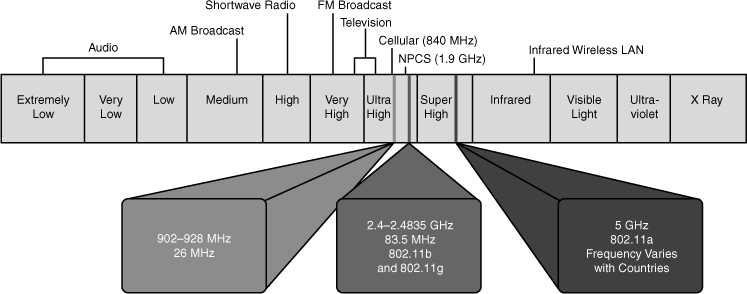
![]() As implied in the list of communications method, wireless in the campus uses the spread spectrum methodology. The spread spectrum wireless focus is on the three unlicensed bands: 900 MHz, 2.4 GHz, and 5 GHz. The 900-MHz and 2.4-GHz bands are referred to as the Industrial, Scientific, and Medical (ISM) bands, and the 5-GHz band is commonly referred to as the Unlicensed National Information Infrastructure (UNII) band.
As implied in the list of communications method, wireless in the campus uses the spread spectrum methodology. The spread spectrum wireless focus is on the three unlicensed bands: 900 MHz, 2.4 GHz, and 5 GHz. The 900-MHz and 2.4-GHz bands are referred to as the Industrial, Scientific, and Medical (ISM) bands, and the 5-GHz band is commonly referred to as the Unlicensed National Information Infrastructure (UNII) band.
![]() Figure 7-1 refers to the frequencies for these bands. They are as follows:
Figure 7-1 refers to the frequencies for these bands. They are as follows:
-
 900-MHz band: 902 MHz to 928 MHz
 -
 2.4-GHz band: 2.4 GHz to 2.483 GHz
 -
 5-GHz band: 5.150 MHz to 5.350 MHz, 5.725 MHz to 5.825 MHz, with some countries supporting middle bands between 5.350 MHz and 5.825 MHz
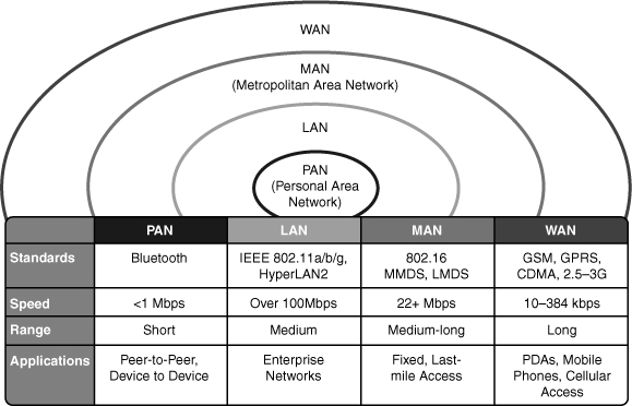
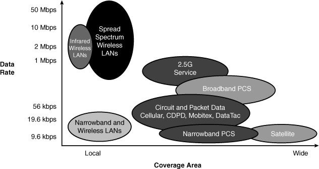
![]() There are many different types of networks offered. Each unique network provides some defined coverage area. Figure 7-2 lists each wireless technology and illustrates the corresponding coverage areas.
There are many different types of networks offered. Each unique network provides some defined coverage area. Figure 7-2 lists each wireless technology and illustrates the corresponding coverage areas.
![]() The following is a brief list of the different applications of wireless networks, starting with the smallest area:
The following is a brief list of the different applications of wireless networks, starting with the smallest area:
-
 Personal-area network (PAN): Typically designed to cover your personal workspace. Radios are typically low-powered, do not offer options in antenna selection, and limit the size of the coverage area to approximately 15 to 20 feet radially. One such PAN network is Bluetooth. Good examples of this technology are communications between PCs and peripherals or between wireless phones and headsets. In the PAN wireless network, the customer owns 100 percent of the network; therefore, no airtime charges are incurred.
 -
 LAN: Designed to be an enterprise-based network that enables for complete suites of enterprise applications to be used without wires. A LAN typically delivers Ethernet-capable speeds (up to 10 Gbps). In the LAN wireless network, the customer owns 100 percent of the network; therefore, no airtime charges are incurred.
 -
 Metropolitan-area network (MAN): Deployed inside a metropolitan area, allowing wireless connectivity throughout an urban area. A MAN typically delivers up to broadband speeds (similar to digital subscriber line [DSL]) but is not capable of Ethernet speeds. In the wireless MAN, the wireless network might be from a licensed carrier, requiring the customer to purchase airtime, or it might be built out and supported by one entity, such as a police department. A new standard coming of age in the MAN is WiMAX. Information is available on the Internet with regard to WiMAX.
 -
 WAN: Typically slower in speed but offers more coverage, sometimes including rural areas. Because of their vast deployment, all wireless WANs require that a customer purchase airtime for data transmission.
![]() Campus networks, of course, apply LAN-based wireless networks (WLAN). Cisco offers a wide range of wireless products for the LAN and other applications such the MAN and WAN. WLAN products have limited range but relatively high-speeds in excess of 108 Mbps. Figure 7-3 illustrates the coverage areas and data rates of various wireless data networks in use today for WLANs.
Campus networks, of course, apply LAN-based wireless networks (WLAN). Cisco offers a wide range of wireless products for the LAN and other applications such the MAN and WAN. WLAN products have limited range but relatively high-speeds in excess of 108 Mbps. Figure 7-3 illustrates the coverage areas and data rates of various wireless data networks in use today for WLANs.
![]() For the purpose of applying WLANs to the campus network, note the speeds and range of WLAN products discussed at a high-level in this section. Because there are entire books dedicated to WLANs, it would be too much material to cover the technology in detail from a switching perspective. As such, the remainder of information on WLANs in this chapter focuses on planning and preparation in the campus network. Consult Cisco.com or other texts for additional information on how WLANs operate.
For the purpose of applying WLANs to the campus network, note the speeds and range of WLAN products discussed at a high-level in this section. Because there are entire books dedicated to WLANs, it would be too much material to cover the technology in detail from a switching perspective. As such, the remainder of information on WLANs in this chapter focuses on planning and preparation in the campus network. Consult Cisco.com or other texts for additional information on how WLANs operate.
Cisco WLAN Solutions as Applied to Campus Networks
![]() Cisco classifies its campus network WLAN solutions and products into a framework denoted as the Cisco Unified Wireless Network, which is broken down into the following subelements:
Cisco classifies its campus network WLAN solutions and products into a framework denoted as the Cisco Unified Wireless Network, which is broken down into the following subelements:
-
 Client devices: Cisco Compatible or Cisco Aironet 802.11a/b/g/ client adapters are strongly recommended for the Cisco Unified Wireless Network. However, with more than 90 percent of shipping client devices certified as Cisco-compatible, almost any client device that you select should be Cisco-compatible certified. In addition, Cisco-compatible client devices interoperate with and support innovative and unique Cisco Unified Wireless Network features, such as fast secure roaming, integrated IPS, location services, and a variety of extensible authentication types.
 -
 Mobility platform: Cisco offers access points and bridges for the carpeted enterprise, ruggedized environments, and challenging environments, such as the outdoors. Cisco Aironet lightweight access points are dynamically configured and managed through Lightweight Access Point Protocol (LWAPP), which is discussed later in this section. In addition, Cisco Aironet autonomous access points have the option to be converted to operate as lightweight access points running the LWAPP are supported. Note that not all Cisco Aironet autonomous AP models can be converted to LWAPP APs; see Cisco.com for more information.
Note  Cisco offers a wide range of wireless AP models. For a complete and current reference of AP models, consult references to wireless AP models on Cisco.com.
 -
 Network unification: The Cisco Unified Wireless Network leverages the customer’s existing wired network and investment in Cisco products. It supports a seamless network infrastructure across a range of platforms by unification with Cisco WLAN controllers.
 -
 World-class network management: Cisco delivers a world-class network management system (NMS) that visualizes and helps secure your air space. The Cisco Wireless Control Systems (WCS) supports WLAN planning and design, radio frequency management, location tracking, and IPS, in addition to WLAN systems configuration, monitoring, and management. This platform easily manages multiple controllers and their associated lightweight access points.
 -
 Unified advanced services: Cisco provides unified support of leading-edge applications. Cisco offers advanced services that are industry leading, innovative, and comprehensive. Wireless lightweight access points, location appliances, and wireless IP phones deliver the Cisco Unified Wireless Network advanced services.
![]() Although detailed information and configuration of these elements is not necessary for switching, they can be referenced in voice deployments. The next section discusses similarities and differences of LANs and WLANs.
Although detailed information and configuration of these elements is not necessary for switching, they can be referenced in voice deployments. The next section discusses similarities and differences of LANs and WLANs.
Comparing and Contrasting WLANs and LANs
![]() As previously noted, wired LANs require that users locate in one place and stay there. Because WLANs are an extension to the wired LAN network, they enable users to be mobile while using the mobile devices in different places without a wired network connection. A WLAN can be an overlay to, or substitute for, a traditional wired LAN network.
As previously noted, wired LANs require that users locate in one place and stay there. Because WLANs are an extension to the wired LAN network, they enable users to be mobile while using the mobile devices in different places without a wired network connection. A WLAN can be an overlay to, or substitute for, a traditional wired LAN network.
![]() With Cisco WLANs, mobile users can
With Cisco WLANs, mobile users can
-
 Move freely around a facility
 -
 Enjoy real-time access to the wired LAN at wired Ethernet speeds
 -
 Access all the resources of wired LANs
![]() WLANs are essentially 802.11 LANs; recall the 802 nomenclature of 802 from CCNA switching. Fundamentally, the data in WLANs is sent over radio waves. In wired LANs, the data is sent over wires. However, the network interface of WLANs looks similar to wired LANs for the user.
WLANs are essentially 802.11 LANs; recall the 802 nomenclature of 802 from CCNA switching. Fundamentally, the data in WLANs is sent over radio waves. In wired LANs, the data is sent over wires. However, the network interface of WLANs looks similar to wired LANs for the user.
![]() The following list summarizes similarities and differences between wired and wireless LANs:
The following list summarizes similarities and differences between wired and wireless LANs:
-
 Both WLANs and wired LANs define the physical and data link layers and use MAC addresses. The same protocols and applications can be used over LANs and WLANs. Examples of such protocols are the IP and IP Security (IPsec) protocol for virtual private networks (VPN). Examples of applications are web, FTP, and Simple Network Management Protocol (SNMP) management.
 -
 In WLANs, radio frequencies are used as the physical layer of the network.
 -
 WLANs use carrier sense multiple access collision avoidance (CSMA/CA) instead of carrier sense multiple access collision detection (CSMA/CD), which is used by Ethernet LANs. Collision detection is not possible because a sending station cannot receive at the same time that it is transmitting and, therefore, cannot detect a collision. Instead, the Request To Send (RTS) and Clear To Send (CTS) protocols are used to avoid collisions.
 -
 WLANs use a different frame format than wired Ethernet LANs. Additional information for WLANs is required in the Layer 2 header of the frame.
 -
 Radio waves used by WLANs have problems not found in wires.
 -
 Connectivity issues in WLANs can be caused by coverage problems, RF transmission, multipath distortion, and interference from other wireless services or other WLANs.
 -
 Privacy issues are possible because radio frequencies can reach outside the facility and physical cable plan.
 -
 In WLANs, mobile clients are used to connect to the network.
 -
 Mobile devices are often battery-powered.
 -
 WLANs are available worldwide; however, because WLANs use radio frequencies, they must follow country-specific regulations for RF power and frequencies. This requirement does not apply to wired LANs.
![]() WLANs obviously present challenges beyond wire LANs. Discussion of the problems, possible solutions, and further technical information about WLAN operations is outside the scope of this text. Consult Cisco.com for more information. The next section of the chapter introduces the standalone versus controller-based approaches to WLAN deployments, a topic critical to planning WLAN deployments in the campus.
WLANs obviously present challenges beyond wire LANs. Discussion of the problems, possible solutions, and further technical information about WLAN operations is outside the scope of this text. Consult Cisco.com for more information. The next section of the chapter introduces the standalone versus controller-based approaches to WLAN deployments, a topic critical to planning WLAN deployments in the campus.
Standalone Versus Controller-Based Approaches to WLAN Deployments in the Campus Network
![]() For a deployment of a Cisco Unified Wireless Network into a campus network, two deployment strategies exist for WLAN solutions. These deployment solutions are the standalone WLAN solution and the controller-based WLAN solution.
For a deployment of a Cisco Unified Wireless Network into a campus network, two deployment strategies exist for WLAN solutions. These deployment solutions are the standalone WLAN solution and the controller-based WLAN solution.
![]() Synonymous with its naming, the standalone WLAN solution uses independent access points as a deployment strategy. For scaled WLAN deployments that use the standalone solution, Cisco recommends the use of Cisco Wireless LAN Solution Engine (WLSE) for centralized management and monitoring. Standalone WLAN solutions may be referred to as autonomous WLAN solutions in other documents and texts.
Synonymous with its naming, the standalone WLAN solution uses independent access points as a deployment strategy. For scaled WLAN deployments that use the standalone solution, Cisco recommends the use of Cisco Wireless LAN Solution Engine (WLSE) for centralized management and monitoring. Standalone WLAN solutions may be referred to as autonomous WLAN solutions in other documents and texts.
![]() Conversely, the controller-based WLAN solution uses centralized management systems to not only manage and monitor the access point, but also control, configure, and operate each access point. Controller-based WLAN solutions might be referred to as lightweight WLAN solutions in other documents and texts.
Conversely, the controller-based WLAN solution uses centralized management systems to not only manage and monitor the access point, but also control, configure, and operate each access point. Controller-based WLAN solutions might be referred to as lightweight WLAN solutions in other documents and texts.
![]() In brief, standalone WLAN Solutions (Autonomous WLAN Solutions) are deployed using independent access points and optionally use a WLSE for centralized management. Controller-based WLAN solutions are deployed with a centralized controller, whereas the controller not only manages and monitors the access, but also controls, configures, and operates each access point.
In brief, standalone WLAN Solutions (Autonomous WLAN Solutions) are deployed using independent access points and optionally use a WLSE for centralized management. Controller-based WLAN solutions are deployed with a centralized controller, whereas the controller not only manages and monitors the access, but also controls, configures, and operates each access point.
![]() The following two subsections dive further into each WLAN solution to provide background information necessary to plan a campus network deployment.
The following two subsections dive further into each WLAN solution to provide background information necessary to plan a campus network deployment.
Standalone WLAN Solution
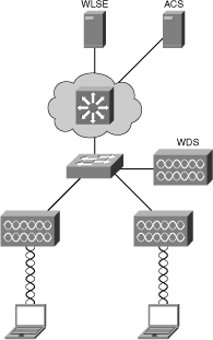
![]() Figure 7-4 highlights a typical model for deploying the standalone WLAN solution in a campus network.
Figure 7-4 highlights a typical model for deploying the standalone WLAN solution in a campus network.
![]() As previously noted, the standalone WLAN solution uses an independent (standalone) access point with centralized management and monitoring through a WLSE. Moreover, this solution also uses access control servers (ACS) in either a RADIUS or TACACS+ configuration for access control. Wireless domain services might be provided for radio frequency management and secure roaming. The Cisco switches deployed in the campus might support power of Ethernet (POE) to power the access points. PoE is discussed in further detail later in this chapter.
As previously noted, the standalone WLAN solution uses an independent (standalone) access point with centralized management and monitoring through a WLSE. Moreover, this solution also uses access control servers (ACS) in either a RADIUS or TACACS+ configuration for access control. Wireless domain services might be provided for radio frequency management and secure roaming. The Cisco switches deployed in the campus might support power of Ethernet (POE) to power the access points. PoE is discussed in further detail later in this chapter.
![]() Because each access point operates independently of each other in a standalone solution, the access points simply translate the wireless media (denoted 802.11) to Ethernet media (802.3.) and send the frames to the Cisco switch. The Cisco switch interprets the frames from the access point as any other Ethernet and switches the frames accordingly. In other words, the access point is relatively transparent to the switch from a traffic perspective.
Because each access point operates independently of each other in a standalone solution, the access points simply translate the wireless media (denoted 802.11) to Ethernet media (802.3.) and send the frames to the Cisco switch. The Cisco switch interprets the frames from the access point as any other Ethernet and switches the frames accordingly. In other words, the access point is relatively transparent to the switch from a traffic perspective.
Controller-Based WLAN Solution
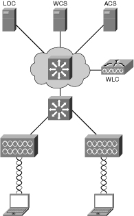
![]() As previously discussed, the controller-based solution provides for centralized operation compared to a standalone solution. Figure 7-5 illustrates the components of a controller-based WLAN solution.
As previously discussed, the controller-based solution provides for centralized operation compared to a standalone solution. Figure 7-5 illustrates the components of a controller-based WLAN solution.
![]() The definition of the devices shown in Figure 7-5 as part of a controller-based solution are described as follows:
The definition of the devices shown in Figure 7-5 as part of a controller-based solution are described as follows:
-
 Controller-based access points.
 -
 Network infrastructure with router and switches. Switches can be used to supply power to the access points (PoE).
 -
 Cisco Wireless LAN Controller (WLC) for the control, configuration, and monitoring of the access points.
 -
 Cisco Wireless Control System (WCS) for WLAN management (recommended).
 -
 Cisco Wireless Location Appliance for location tracking (optional application server).
 -
 Cisco Secure Access Control Server (ACS) for wireless security and authentication using RADIUS and TACACS+ protocol.
![]() The controller-based solution divides the processing of the 802.11 wireless protocols between the access points and a centralized Cisco Wireless LAN Controller (WLC). The processing of the 802.11 data and management protocols and the access point functionality is also split between the access points and the WLC. Even though this process sounds confusing, the designation between what the access points manages and what the WLC manages is simple. Most of the time, the access point manages critical functions, whereas the controller manages all the other functions.
The controller-based solution divides the processing of the 802.11 wireless protocols between the access points and a centralized Cisco Wireless LAN Controller (WLC). The processing of the 802.11 data and management protocols and the access point functionality is also split between the access points and the WLC. Even though this process sounds confusing, the designation between what the access points manages and what the WLC manages is simple. Most of the time, the access point manages critical functions, whereas the controller manages all the other functions.
| Note |
|
| Note |
|
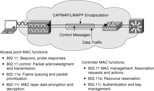
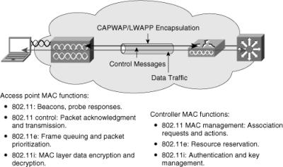
![]() Figure 7-6 illustrates the behavior of the split processing between the access point and the WLC.
Figure 7-6 illustrates the behavior of the split processing between the access point and the WLC.
![]() As noted in Figure 7-6, the access point handles the portions of the protocol that have real-time requirements to include the following:
As noted in Figure 7-6, the access point handles the portions of the protocol that have real-time requirements to include the following:
-
 Frame exchanges handshake between a client and access point when transferring a frame over the air
 -
 Transmission of beacon frames
 -
 Buffering and transmission of frames for clients in power save operation
 -
 Response to probe request frames from clients
 -
 Forwarding notification of received probe requests to the controller
 -
 Providing real-time signal quality information to the controller with every received frame
 -
 Monitoring each radio channel for noise, interference, and presence of other WLANs
 -
 Monitoring for the presence of other access points
![]() All remaining functionality is handled in the Cisco WLC, where time-sensitivity is not a concern and controllerwide visibility is required. The WLC functions include the following:
All remaining functionality is handled in the Cisco WLC, where time-sensitivity is not a concern and controllerwide visibility is required. The WLC functions include the following:
-
 802.11 authentication and de-authentication
 -
 802.11 association and reassociation (mobility)
 -
 802.11 frame translation and bridging
![]() The next two subsections focus on traffic handling and traffic flow of the controller-based solutions.
The next two subsections focus on traffic handling and traffic flow of the controller-based solutions.
Traffic Handling in Controller-Based Solutions
![]() Traffic handling in controller-based solutions is different than standalone solutions. Consider the following notes when planning for a wireless deployment in a campus network:
Traffic handling in controller-based solutions is different than standalone solutions. Consider the following notes when planning for a wireless deployment in a campus network:
-
 Data and control messages are encapsulated between the access point and the WLAN controller using the Control and Provisioning of Wireless Access Points (CAPWAP) method or the Lightweight Access Point Protocol (LWAPP). Although both are standards-based, LWAPP was never adopted by any other vendor other than Cisco.
 -
 Control traffic between the access point and the controller is encapsulated with the LWAPP or CAPWAP and encrypted.
 -
 The data traffic between the access point and controller is also encapsulated with LWAPP or CAPWAP. The data traffic is not encrypted. It is switched at the WLAN controller, where VLAN tagging and quality of service (QoS) are also applied.
 -
 The access point accomplishes real-time frame exchange and certain real-time portions of MAC management. All client data traffic is sent via the WLAN controller.
 -
 WLAN controller and access point can be in the same or different broadcast domains and IP subnets. Access points obtain an IP address via DHCP, and then join a controller via a CAPWAP or LWAPP discovery mechanism.
![]() The next subsection discusses the traffic flow in a controller-based solution.
The next subsection discusses the traffic flow in a controller-based solution.
Traffic Flow in a Controller-Based Solution
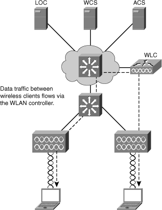
![]() As previously noted, all traffic in a controller-based solution flows throw the WLC. For example, Figure 7-7 illustrates two clients communicating over a wireless network in a controller-based solution. As alluded to previously in Figure 7-6, the WLC is generally deployed in the distribution layer.
As previously noted, all traffic in a controller-based solution flows throw the WLC. For example, Figure 7-7 illustrates two clients communicating over a wireless network in a controller-based solution. As alluded to previously in Figure 7-6, the WLC is generally deployed in the distribution layer.
![]() The traffic between the two wireless mobile stations is forwarded from the access points to the controller and then sent to wireless mobile stations, respectively. Denote the traffic flows to the WLC and not between the mobile stations directly. The campus network switch simply switches Ethernet frames and is not aware that the frames ultimately end at a wireless client.
The traffic between the two wireless mobile stations is forwarded from the access points to the controller and then sent to wireless mobile stations, respectively. Denote the traffic flows to the WLC and not between the mobile stations directly. The campus network switch simply switches Ethernet frames and is not aware that the frames ultimately end at a wireless client.
| Note |
|
Hybrid Remote Edge Access Points (HREAP)
![]() HREAP are useful for providing high-availability of controller-based wireless solutions in remote offices. The purpose of these access points is to still offer wireless client connectivity when their connection to the controller (WLC) is lost. A typical controller-based access point always needs connectivity to its controller. When this connectivity is lost, the access point stops offering wireless services and starts looking for another controller. It restores wireless services only when it has regained connectivity to a controller.
HREAP are useful for providing high-availability of controller-based wireless solutions in remote offices. The purpose of these access points is to still offer wireless client connectivity when their connection to the controller (WLC) is lost. A typical controller-based access point always needs connectivity to its controller. When this connectivity is lost, the access point stops offering wireless services and starts looking for another controller. It restores wireless services only when it has regained connectivity to a controller.
![]() HREAPs are controller-based access points. The main difference with standard controller-based access points is that the HREAP can survive the loss of connectivity to its controller. The HREAP reverts to a mode close to a standalone access point and remains to offer wireless access to its wireless clients.
HREAPs are controller-based access points. The main difference with standard controller-based access points is that the HREAP can survive the loss of connectivity to its controller. The HREAP reverts to a mode close to a standalone access point and remains to offer wireless access to its wireless clients.
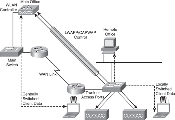
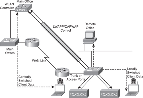
![]() Figure 7-8 illustrates sample behavior of a HREAP solution.
Figure 7-8 illustrates sample behavior of a HREAP solution.
![]() The HREAP is usually adapted to remote offices where only one or two access points are deployed; generally remote offices use wireless deployments for only a few access points because the size is usually small. Moreover, in a remote office situation, the controller is not local but accessed through a WAN connection. The HREAP might also be adapted to small offices with only one controller and no backup controller. Figure 7-8 illustrates an example of HREAP.
The HREAP is usually adapted to remote offices where only one or two access points are deployed; generally remote offices use wireless deployments for only a few access points because the size is usually small. Moreover, in a remote office situation, the controller is not local but accessed through a WAN connection. The HREAP might also be adapted to small offices with only one controller and no backup controller. Figure 7-8 illustrates an example of HREAP.
| Note |
|
Review of Standalone and Controller-Based WLAN Solutions
![]() The two WLAN solutions have different characteristics and advantages. Obviously for scaled wireless deployments, the controller-based solution offers significant advantages in terms of centralizing resources. Per the Cisco wireless design guides, any campus network with more than 200 users should utilize a controller-based solution for wireless deployments.
The two WLAN solutions have different characteristics and advantages. Obviously for scaled wireless deployments, the controller-based solution offers significant advantages in terms of centralizing resources. Per the Cisco wireless design guides, any campus network with more than 200 users should utilize a controller-based solution for wireless deployments.
![]() Table 7-1 highlights and reviews the main differences to consider when planning for wireless network deployment in the campus network.
Table 7-1 highlights and reviews the main differences to consider when planning for wireless network deployment in the campus network.
|
|
| |
|---|---|---|
|
|
|
|
|
|
|
|
|
|
|
|
|
|
|
|
|
|
|
|
Gathering Requirements for Planning a Wireless Deployment
![]() Wireless technology spans the scope of the topics covered in this text. Any comprehensive plan for a wireless deployment in a campus network should include advice from a trained specialist or consultant as a best practice.
Wireless technology spans the scope of the topics covered in this text. Any comprehensive plan for a wireless deployment in a campus network should include advice from a trained specialist or consultant as a best practice.
![]() In review, you can use the following list of wireless requirements as a guide when working with specialists or consultants when planning a wireless deployment:
In review, you can use the following list of wireless requirements as a guide when working with specialists or consultants when planning a wireless deployment:
-
 Collect requirements to determine how many ports of what type are needed and how they should be configured.
 -
 Check the existing network to verify how the requirements can integrate into the existing deployment. You will often find that, beyond the pure port count issue, the impact on bandwidth might imply additional connections.
 -
 Plan additional equipment needed to fulfill the requirements.
 -
 Implement new network components.
![]() Moreover, due to the nature of access point behavior, consider building a test plan to verify acceptable wireless implementation. In review of the behavior of an initial connection of a wireless client, it first detects the wireless network and tries to connect at Layer 2 (using 802.11). This connection might imply an 802.1X dialog between the access point (in autonomous mode) or the controller and a AAA server. When this step is complete, the wireless client tries to move to Layer 3 and obtains an IP address. The wireless client then has IP reachability to the network. Knowing these steps can help you troubleshoot wireless connectivity issues. For example, if the controller cannot communicate with the RADIUS server, the client might not associate to the wireless network.
Moreover, due to the nature of access point behavior, consider building a test plan to verify acceptable wireless implementation. In review of the behavior of an initial connection of a wireless client, it first detects the wireless network and tries to connect at Layer 2 (using 802.11). This connection might imply an 802.1X dialog between the access point (in autonomous mode) or the controller and a AAA server. When this step is complete, the wireless client tries to move to Layer 3 and obtains an IP address. The wireless client then has IP reachability to the network. Knowing these steps can help you troubleshoot wireless connectivity issues. For example, if the controller cannot communicate with the RADIUS server, the client might not associate to the wireless network.
![]() The following list illustrates a sample test for verifying a wireless deployment that can be used as a guide for creating your own test plan:
The following list illustrates a sample test for verifying a wireless deployment that can be used as a guide for creating your own test plan:
-
 Can you reach the AP or WLC from management stations?
 -
 Can the AP reach the DHCP server?
 -
 Does the AP get an IP address from the DHCP server?
 -
 Can the WLC reach the Radius or TACACS+ server?
 -
 Does the client get an IP address?
 -
 Can the client access network, server, or Internet services?
 Planning for the Campus Network to Support Voice
![]() Voice services running alongside the data network in the campus are becoming a standard of enterprise networks over traditional telephony networks for many reasons. As previously discussed, cost-savings is a major reason for voice deployments in the campus. Voice deployments in the campus are often referred to as VoIP deployments because from a technology perspective, voice in the campus network runs on top of TCP/IP. Nevertheless, the Return on Investment (ROI) associated with VoIP is significant as VoIP does require an initial start-up cost. However, the initial start-up cost will be returned in cost-savings over the life of the VoIP installation.
Voice services running alongside the data network in the campus are becoming a standard of enterprise networks over traditional telephony networks for many reasons. As previously discussed, cost-savings is a major reason for voice deployments in the campus. Voice deployments in the campus are often referred to as VoIP deployments because from a technology perspective, voice in the campus network runs on top of TCP/IP. Nevertheless, the Return on Investment (ROI) associated with VoIP is significant as VoIP does require an initial start-up cost. However, the initial start-up cost will be returned in cost-savings over the life of the VoIP installation.
![]() From a planning point-of-view, because the telephony services associated with VoIP runs over the campus network, data and voice application traffic must harmoniously coexist. As such, mechanisms must be set in place to differentiate traffic and to offer priority processing to delay sensitive voice traffic. We have all experienced the situation of poor audio quality, echo, jitter, and drop audio on our cell phones. Without careful planning, VoIP in the campus network might experience similar behaviors.
From a planning point-of-view, because the telephony services associated with VoIP runs over the campus network, data and voice application traffic must harmoniously coexist. As such, mechanisms must be set in place to differentiate traffic and to offer priority processing to delay sensitive voice traffic. We have all experienced the situation of poor audio quality, echo, jitter, and drop audio on our cell phones. Without careful planning, VoIP in the campus network might experience similar behaviors.
![]() To solve the differentiation problem, Cisco switches use QoS policies to mark and qualify traffic. In addition, Cisco switches can utilize a specific VLAN to keep voice traffic separate from other data to ensure that it is carried through the network with special handling and with minimal delay. Despite the specific configuration or implementation, design and implementation considerations need to be made for all campus switches supporting VoIP.
To solve the differentiation problem, Cisco switches use QoS policies to mark and qualify traffic. In addition, Cisco switches can utilize a specific VLAN to keep voice traffic separate from other data to ensure that it is carried through the network with special handling and with minimal delay. Despite the specific configuration or implementation, design and implementation considerations need to be made for all campus switches supporting VoIP.
| Note |
|
Introduction to Unified Communications
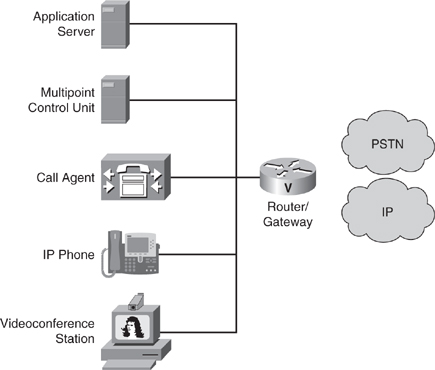
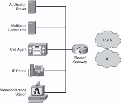
![]() For reference when planning VoIP integration into the campus network, you need to review the entire VoIP architecture. Cisco refers to its architecture and suite of VoIP products and related services as Unified Communications. Unified Communications include more products and services than just the Cisco IP Phone. Figure 7-9 illustrates the products of the Cisco Unified Communications suite.
For reference when planning VoIP integration into the campus network, you need to review the entire VoIP architecture. Cisco refers to its architecture and suite of VoIP products and related services as Unified Communications. Unified Communications include more products and services than just the Cisco IP Phone. Figure 7-9 illustrates the products of the Cisco Unified Communications suite.
![]() The devices in Figure 7-9 are summarized as follows:
The devices in Figure 7-9 are summarized as follows:
-
 IP Phone: Provides IP voice to the desktop.
 -
 Gatekeeper: Provides connection admission control (CAC), bandwidth control and management, and address translation.
 -
 Gateway: Provides translation between VoIP and non-VoIP networks, such as the public switched telephone network (PSTN). It also provides physical access for local analog and digital voice devices, such as telephones, fax machines, key sets, and PBXs.
 -
 Multipoint control unit: Provides real-time connectivity for participants in multiple locations to attend the same videoconference or meeting.
 -
 Call agent: Provides call control for IP phones, CAC, bandwidth control and management, and telephony address translation for IP addresses or telephone numbers.
 -
 Application server: Provides services such as voice mail, unified messaging, and Cisco Unified Communications Manager Attendant Console.
 -
 Videoconference station: Provides access for end-user participation in videoconferencing. The videoconference station contains a video capture device for video input and a microphone for audio input. The user can view video streams and hear the audio that originates at a remote user station.
![]() The deployment of Unified Communications may include either components, such as software voice applications, interactive voice response (IVR) systems, and softphones, provide additional services to meet the communications needs of your specific enterprise deployment. For planning purposes, a Unified Communications deployment may require assistance from other specialists or consultants.
The deployment of Unified Communications may include either components, such as software voice applications, interactive voice response (IVR) systems, and softphones, provide additional services to meet the communications needs of your specific enterprise deployment. For planning purposes, a Unified Communications deployment may require assistance from other specialists or consultants.
Campus Network Design Requirements for Deploying VoIP
![]() Voice traffic has extremely stringent QoS requirements. Voice traffic generally generates a smooth demand on bandwidth and has a minimal impact on other traffic, as long as voice traffic is managed.
Voice traffic has extremely stringent QoS requirements. Voice traffic generally generates a smooth demand on bandwidth and has a minimal impact on other traffic, as long as voice traffic is managed.
![]() When planning for a VoIP deployment, consider the following traffic requirements:
When planning for a VoIP deployment, consider the following traffic requirements:
-
 Voice packets are small, typically between 60 bytes and 120 bytes in size.
 -
 VoIP cannot tolerate drop or delay because it can lead to poor voice quality.
 -
 VoIP uses UDP because TCP retransmit capabilities are useless for voice.
 -
 Specifically, for optimal voice quality, delay should be less than 150 ms one way.
 -
 Although no packet loss is ideal, acceptable packet loss is 1 percent.
![]() The QoS requirements for data traffic vary greatly. Different applications, such as a human resources application versus an ATM application, have different demands on the network. Even different versions of the same application can have varying network traffic characteristics.
The QoS requirements for data traffic vary greatly. Different applications, such as a human resources application versus an ATM application, have different demands on the network. Even different versions of the same application can have varying network traffic characteristics.
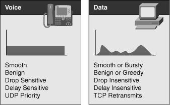
![]() Data traffic can demonstrate either a smooth or bursty characteristic, depending on the application, but it differs from voice and video in terms of delay and drop sensitivity. Almost all data applications can tolerate some delay and generally can tolerate high drop rates. Figure 7-10 illustrates typical traffic rates of voice traffic versus application traffic.
Data traffic can demonstrate either a smooth or bursty characteristic, depending on the application, but it differs from voice and video in terms of delay and drop sensitivity. Almost all data applications can tolerate some delay and generally can tolerate high drop rates. Figure 7-10 illustrates typical traffic rates of voice traffic versus application traffic.
![]() Because data traffic can tolerate drops, the retransmit capabilities of TCP become important and, as a result, many data applications use TCP. Voice traffic uses UDP because there is no need to retransmit drop frames as the voice is real time.
Because data traffic can tolerate drops, the retransmit capabilities of TCP become important and, as a result, many data applications use TCP. Voice traffic uses UDP because there is no need to retransmit drop frames as the voice is real time.
![]() In enterprise networks, important (business-critical) applications are usually easy to identify. Most applications can be identified based on TCP or UDP port numbers. Some applications use dynamic port numbers that, to some extent, make classifications more difficult. Cisco IOS Software supports network-based application recognition (NBAR), which can be used to recognize dynamic port applications.
In enterprise networks, important (business-critical) applications are usually easy to identify. Most applications can be identified based on TCP or UDP port numbers. Some applications use dynamic port numbers that, to some extent, make classifications more difficult. Cisco IOS Software supports network-based application recognition (NBAR), which can be used to recognize dynamic port applications.
![]() Consequently, it is important to plan for QoS in the campus for voice traffic to minimize traffic drops and latency in the campus network. Voice traffic is generally low-bandwidth compared to available bandwidth in the campus network.
Consequently, it is important to plan for QoS in the campus for voice traffic to minimize traffic drops and latency in the campus network. Voice traffic is generally low-bandwidth compared to available bandwidth in the campus network.
| Note |
|
![]() The application of QoS occurs throughout the campus based on specific QoS configuration. The “Understanding QoS” section goes into detail about preparing and implementing QoS. The next section discusses planning for video in the campus network.
The application of QoS occurs throughout the campus based on specific QoS configuration. The “Understanding QoS” section goes into detail about preparing and implementing QoS. The next section discusses planning for video in the campus network.
 Planning for the Campus Network to Support Video
![]() For networking professionals, video is often seen as just a Layer 7 application. Under this generic term, many different types of applications may be grouped, each of them having its own set of usage and technical specifications. Video applications are usually seen as bandwidth-intensive. Bandwidth-intensive applications are so named because they send a large number of frames onto the network. The content of the frame plays an important role in the overall bandwidth consumption. The content of the frame depends on the type of application for which video is used.
For networking professionals, video is often seen as just a Layer 7 application. Under this generic term, many different types of applications may be grouped, each of them having its own set of usage and technical specifications. Video applications are usually seen as bandwidth-intensive. Bandwidth-intensive applications are so named because they send a large number of frames onto the network. The content of the frame plays an important role in the overall bandwidth consumption. The content of the frame depends on the type of application for which video is used.
![]() Some video applications are real time, such as video conferencing or TelePresence. The main concern for this type of video is real time. Frames must transit without delay, and QoS is a critical element. Voice might be contained in the video flow or sent as a distinct flow.
Some video applications are real time, such as video conferencing or TelePresence. The main concern for this type of video is real time. Frames must transit without delay, and QoS is a critical element. Voice might be contained in the video flow or sent as a distinct flow.
![]() Some other video applications are not as sensitive to real-time issues. They usually are one-way streams, where a client station is playing a video stream that is sent from a source. The client station might buffer part of the video flow. The main concern is often quality, and quality depends on several factors such as resolution, number of frames per second, type of codec, and so on, which is not dependent on the design of the campus network. A practical application of one-way streams is on-demand video used for training purposes.
Some other video applications are not as sensitive to real-time issues. They usually are one-way streams, where a client station is playing a video stream that is sent from a source. The client station might buffer part of the video flow. The main concern is often quality, and quality depends on several factors such as resolution, number of frames per second, type of codec, and so on, which is not dependent on the design of the campus network. A practical application of one-way streams is on-demand video used for training purposes.
![]() Because multiple persons might receive one-way video streams simultaneously, as in the case of watching a live video feed, the video feed might use multicast to send the traffic to multiple users simultaneously instead of sending traffic to each user autonomously. The “Understanding IP Multicast” section discusses this concept more. In brief, consider planning for deploying multicast for any application that sends traffic to multiple users concerning especially live video feeds.
Because multiple persons might receive one-way video streams simultaneously, as in the case of watching a live video feed, the video feed might use multicast to send the traffic to multiple users simultaneously instead of sending traffic to each user autonomously. The “Understanding IP Multicast” section discusses this concept more. In brief, consider planning for deploying multicast for any application that sends traffic to multiple users concerning especially live video feeds.
| Note |
|
![]() Note that real-time video applications are often peer-to-peer. Moreover, when planning for deployments, video applications deploy in the access layer just like a voice or data endpoint.
Note that real-time video applications are often peer-to-peer. Moreover, when planning for deployments, video applications deploy in the access layer just like a voice or data endpoint.
Voice and Video Traffic
![]() You need to understand the voice and video traffic profiles associated with video applications in the campus network. These traffic profiles ultimately drive the design of the campus network for a voice or video application.
You need to understand the voice and video traffic profiles associated with video applications in the campus network. These traffic profiles ultimately drive the design of the campus network for a voice or video application.
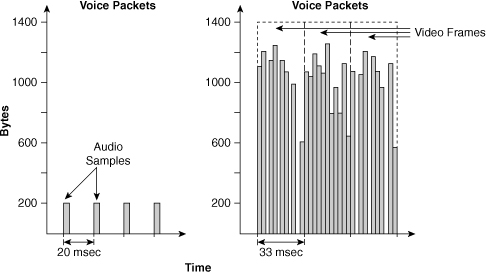
![]() As illustrated in Figure 7-11, a video flow has different characteristics from a voice flow. Voice traffic is usually not bandwidth-intensive but requires steady bandwidth. Commonly, 50 voice packets would need to be sent per second for voice, each packet representing a few hundred bytes worth of voice data.
As illustrated in Figure 7-11, a video flow has different characteristics from a voice flow. Voice traffic is usually not bandwidth-intensive but requires steady bandwidth. Commonly, 50 voice packets would need to be sent per second for voice, each packet representing a few hundred bytes worth of voice data.
![]() Because of the nature of the algorithm used to encode the flow, video traffic has a different pattern. Traffic is often bursty, as each image or group of images needs several packets to be transmitted. Depending on the changes from one image to the next, there might be short time intervals without any network activity or sudden bursts when the whole image needs to be changed.
Because of the nature of the algorithm used to encode the flow, video traffic has a different pattern. Traffic is often bursty, as each image or group of images needs several packets to be transmitted. Depending on the changes from one image to the next, there might be short time intervals without any network activity or sudden bursts when the whole image needs to be changed.
![]() Overall, real-time video streams typically consume a lot of bandwidth and are often bursty, although they usually do not consume all the available bandwidth. Consider these characteristics when preparing the campus network for video and voice.
Overall, real-time video streams typically consume a lot of bandwidth and are often bursty, although they usually do not consume all the available bandwidth. Consider these characteristics when preparing the campus network for video and voice.
Video Traffic Flow in the Campus Network
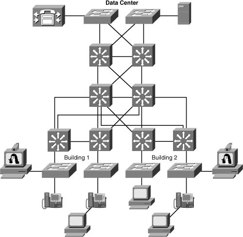
![]() Traffic flow for video applications, in the case of peer-to-peer interactive video, is close to the voice flow. In Figure 7-12, two TelePresence (high-definition video conferencing) stations are communicating. The flow goes from one station to the access switch, then to the distribution switch, then to the core switch before reaching the distribution layer of the second building, and then to the access switch and the second station. This pattern is close to the voice flow between two phones. Just like a voice call, TelePresence stations may rely on a central server from where information about the session can be obtained. A detailed discussion of TelePresence is outside the scope of this book; consult Cisco.com for more details.
Traffic flow for video applications, in the case of peer-to-peer interactive video, is close to the voice flow. In Figure 7-12, two TelePresence (high-definition video conferencing) stations are communicating. The flow goes from one station to the access switch, then to the distribution switch, then to the core switch before reaching the distribution layer of the second building, and then to the access switch and the second station. This pattern is close to the voice flow between two phones. Just like a voice call, TelePresence stations may rely on a central server from where information about the session can be obtained. A detailed discussion of TelePresence is outside the scope of this book; consult Cisco.com for more details.
![]() Data traffic does not often transit from one station to the other. Data clients usually communicate with data centers to upload or download data. Video streaming applications have the same behavior as data: They retrieve information from data centers and have little if no peer-to-peer interaction.
Data traffic does not often transit from one station to the other. Data clients usually communicate with data centers to upload or download data. Video streaming applications have the same behavior as data: They retrieve information from data centers and have little if no peer-to-peer interaction.
![]() As a result, when planning video integration into the campus network, denote whether the following applications will be deployed:
As a result, when planning video integration into the campus network, denote whether the following applications will be deployed:
-
 Video streaming applications, such as video-on-demand training
 -
 Video TV-type applications, such as Cisco IP TV
 -
 IP surveillance applications for security
![]() Denoting these applications and referencing the material in this section can determine campus network design and configuration requirements.
Denoting these applications and referencing the material in this section can determine campus network design and configuration requirements.
Design Requirements for Voice, Data, and Video in the Campus Network
![]() Table 7-2 details the bandwidth, delay, jitter, packet loss, availability, power, security, and management requirements for planning voice, data, and video application in the campus network.
Table 7-2 details the bandwidth, delay, jitter, packet loss, availability, power, security, and management requirements for planning voice, data, and video application in the campus network.
|
|
|
|
|
|---|---|---|---|
|
|
|
|
|
|
|
|
|
|
|
|
|
|
|
|
|
|
|
|
|
|
|
|
|
|
|
|
|
|
|
|
|
|
|
|
|
|
|
|
![]() In review, the tolerance to delay and jitter of video traffic depends on the type of video flow: Real time video, such as video conferencing with embedded voice, has the same delay and jitter constraints as voice traffic. One-way video streams are less sensitive to delay and jitter issues. Most video playing devices can buffer 5 seconds or more worth of video flow.
In review, the tolerance to delay and jitter of video traffic depends on the type of video flow: Real time video, such as video conferencing with embedded voice, has the same delay and jitter constraints as voice traffic. One-way video streams are less sensitive to delay and jitter issues. Most video playing devices can buffer 5 seconds or more worth of video flow.
![]() Video traffic also has little tolerance to packet loss. If too many frames are lost, the image does not refresh properly and the user experience degrades. Here again, the quality depends on the type of application used. Tolerance to packet loss is often higher for slow rate and low-definition real-time interactive video flows than for one-way video streams.
Video traffic also has little tolerance to packet loss. If too many frames are lost, the image does not refresh properly and the user experience degrades. Here again, the quality depends on the type of application used. Tolerance to packet loss is often higher for slow rate and low-definition real-time interactive video flows than for one-way video streams.
![]() The next section discusses QoS, a requirement of most campus network designs, especially those that integrate voice and video.
The next section discusses QoS, a requirement of most campus network designs, especially those that integrate voice and video.

0 comments
Post a Comment