Understanding and Protecting Against VLAN Attacks
![]() On networks using trunking protocols, there is a possibility of rogue traffic “hopping” from one VLAN to another, thereby creating security vulnerabilities.
On networks using trunking protocols, there is a possibility of rogue traffic “hopping” from one VLAN to another, thereby creating security vulnerabilities.
 VLAN Hopping
![]() VLAN hopping is a network attack whereby an end system sends packets to, or collects packets from, a VLAN that should not be accessible to that end system. This is accomplished by tagging the invasive traffic with a specific VLAN ID (VID) or by negotiating a trunk link to send or receive traffic on penetrated VLANs. VLAN hopping can be accomplished by switch spoofing or double tagging.
VLAN hopping is a network attack whereby an end system sends packets to, or collects packets from, a VLAN that should not be accessible to that end system. This is accomplished by tagging the invasive traffic with a specific VLAN ID (VID) or by negotiating a trunk link to send or receive traffic on penetrated VLANs. VLAN hopping can be accomplished by switch spoofing or double tagging.
![]() VLAN hopping attacks refer to a malicious device attempting to access VLANs for which it is not configured. There are two forms of VLAN hopping attacks.
VLAN hopping attacks refer to a malicious device attempting to access VLANs for which it is not configured. There are two forms of VLAN hopping attacks.
![]() The first form is due to the default configuration of the Catalyst switch port. Cisco Catalyst switches enable trunking in auto mode by default. As a result, the interface becomes a trunk upon receiving a DTP frame. An attacker can use this default behavior to access VLANs configured on the switch through one of the following methods:
The first form is due to the default configuration of the Catalyst switch port. Cisco Catalyst switches enable trunking in auto mode by default. As a result, the interface becomes a trunk upon receiving a DTP frame. An attacker can use this default behavior to access VLANs configured on the switch through one of the following methods:
-
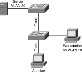
 An attacker can send a malicious DTP frame. Upon receiving the frame, the switch would form a trunk port, which would then give the attacker access to all the VLANs on the trunk. In Figure 6-7, the attacker port becomes a trunk port, and the attacker can attack a victim in any VLAN carried on the trunk.
 -
 In a switch spoofing attack, the network attacker configures a system to spoof itself as a switch. Typically, this is achieved by connecting an unauthorized Cisco switch to the switch port. The authorized switch can send DTP frames and form a trunk. The attacker again has access to all the VLANs through the trunk. In Figure 6-8, an unauthorized switch can form a trunk with the Cisco switch. The attacker device connects to the unauthorized switch and can attack a victim in another VLAN.
![]() The following list describes the switch spoofing sequence of events:
The following list describes the switch spoofing sequence of events:
-
 Attacker gains access to a switch port and sends DTP negotiation frames toward a switch with DTP running and auto negotiation turned on (often, the default settings).
 -
 Attacker and switch negotiate trunking over the port.
 -
 Switch enables all VLANs (default) to traverse the trunk link.
 -
 Attacker sends data to, or collects it from, all VLANs carried on that trunk.
 VLAN Hopping with Double Tagging
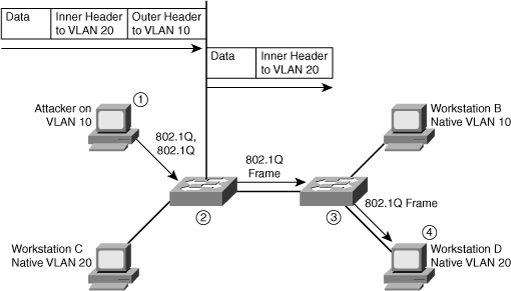
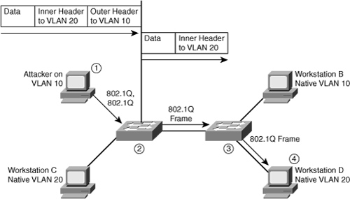
![]() The second form of VLAN hopping attack is possible even if the trunking feature is turned off on the switch port. The attack involves sending frames with a double 802.1Q tag, as shown in Figure 6-9. This attack requires the client to be on a switch other than the attacking switch. Another requirement is that these two switches must be connected in the same VLAN as the attacking switch port or native VLAN of the trunk between the switch and the attacked VLAN.
The second form of VLAN hopping attack is possible even if the trunking feature is turned off on the switch port. The attack involves sending frames with a double 802.1Q tag, as shown in Figure 6-9. This attack requires the client to be on a switch other than the attacking switch. Another requirement is that these two switches must be connected in the same VLAN as the attacking switch port or native VLAN of the trunk between the switch and the attacked VLAN.
![]() In this method of VLAN hopping, any workstation can generate frames with two 802.1Q headers to cause the switch to forward the frames onto a VLAN that would be inaccessible to the attacker through legitimate means.
In this method of VLAN hopping, any workstation can generate frames with two 802.1Q headers to cause the switch to forward the frames onto a VLAN that would be inaccessible to the attacker through legitimate means.
![]() The first switch to encounter the double-tagged frame strips the first tag off the frame, because the first tag (VLAN 10) matches the trunk port native VLAN, and then forwards the frame out.
The first switch to encounter the double-tagged frame strips the first tag off the frame, because the first tag (VLAN 10) matches the trunk port native VLAN, and then forwards the frame out.
![]() The result is that the frame is forwarded, with the inner 802.1Q tag, out all the switch ports as the switch does not have the MAC address in the table because the switch does not recognize that there is a second tag., including trunk ports configured with the native VLAN of the network attacker. The second switch then forwards the packet to the destination based on the VLAN ID in the second 802.1Q header. If the trunk does not match the native VLAN of the attacker, the frame would be untagged and flooded to only the original VLAN.
The result is that the frame is forwarded, with the inner 802.1Q tag, out all the switch ports as the switch does not have the MAC address in the table because the switch does not recognize that there is a second tag., including trunk ports configured with the native VLAN of the network attacker. The second switch then forwards the packet to the destination based on the VLAN ID in the second 802.1Q header. If the trunk does not match the native VLAN of the attacker, the frame would be untagged and flooded to only the original VLAN.
![]() The following steps describe the double-tagging method of VLAN hopping:
The following steps describe the double-tagging method of VLAN hopping:
|
|
|
|
|
|
|
|
|
|
|
|
 Mitigating VLAN Hopping
![]() The measures to defend the network from VLAN hopping are a series of best practices for all switch ports and parameters to follow when establishing a trunk port:
The measures to defend the network from VLAN hopping are a series of best practices for all switch ports and parameters to follow when establishing a trunk port:
-
 Configure all unused ports as access ports so that trunking cannot be negotiated across those links.
 -
 Place all unused ports in the shutdown state and associate them with a VLAN designed for only unused ports, carrying no user data traffic.
 -
 When establishing a trunk link, purposefully configure arguments to achieve the following results:
![]() Other methods to ensure VLAN security is using private VLAN to segregate users and using VLAN ACL to filter traffic within the same VLAN. Private VLAN is explained more in Chapter 2, “Implementing VLANs in Campus Networks.”
Other methods to ensure VLAN security is using private VLAN to segregate users and using VLAN ACL to filter traffic within the same VLAN. Private VLAN is explained more in Chapter 2, “Implementing VLANs in Campus Networks.”
![]() For more information about best practice for configuring Catalyst switches, refer to the following URL on Cisco.com:
For more information about best practice for configuring Catalyst switches, refer to the following URL on Cisco.com:
-
 www.cisco.com/en/US/products/hw/switches/ps700/products_white_paper09186a00801b49a4.shtml
 VLAN Access Control Lists
![]() Access control lists (ACL) are useful for controlling access in a multilayer switched network. This topic describes VACLs and their purpose as part of VLAN security.
Access control lists (ACL) are useful for controlling access in a multilayer switched network. This topic describes VACLs and their purpose as part of VLAN security.
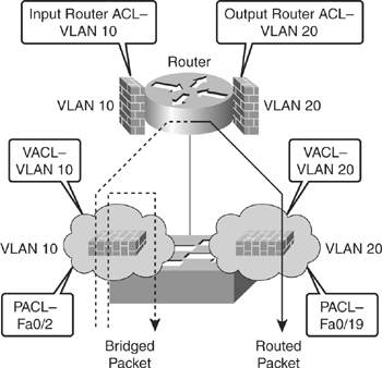
![]() Cisco multilayer switches support three types of ACLs, as shown in Figure 6-10.
Cisco multilayer switches support three types of ACLs, as shown in Figure 6-10.
-
 Router access control lists (RACL): Supported in the TCAM hardware on Cisco multilayer switches. In Catalyst switches, RACL can be applied to any routed interface, such as a switch virtual interface (SVI) or Layer 3 routed port.
 -
 Port access control list (PACL): Filters traffic at the port level. PACLs can be applied on a Layer 2 switch port, trunk port, or EtherChannel port. PACLs act at the Layer 2 port level but can filter based on Layer 3/Layer 4 information.
 -
 VACLs: Also known as VLAN access-maps, apply to all traffic in a VLAN. VACLs support filtering based on Ethertype and MAC addresses. VACLs are order-sensitive, similar to Cisco IOS–based route maps. VACLs can control traffic flowing within the VLAN or control switched traffic, whereas RACLs control only routed traffic.
![]() Catalyst switches support four ACL lookups per packet: input and output security ACL and input and output quality of service (QoS) ACL.
Catalyst switches support four ACL lookups per packet: input and output security ACL and input and output quality of service (QoS) ACL.
![]() The process of combining the ACEs from multiple feature ACLs is known as the ACL merge. Catalyst switches use two methods of performing a merge: order independent and order dependent. With order-independent merge, ACLs are transformed from a series of order-dependent actions to a set of order-independent masks and patterns. The resulting access control entry (ACE) can be large. The merge is processor- and memory-intensive.
The process of combining the ACEs from multiple feature ACLs is known as the ACL merge. Catalyst switches use two methods of performing a merge: order independent and order dependent. With order-independent merge, ACLs are transformed from a series of order-dependent actions to a set of order-independent masks and patterns. The resulting access control entry (ACE) can be large. The merge is processor- and memory-intensive.
![]() Order-dependent merge is a recent improvement on some Catalyst switches in which ACLs retain their order-dependent aspect. The computation is much faster and is less processor-intensive.
Order-dependent merge is a recent improvement on some Catalyst switches in which ACLs retain their order-dependent aspect. The computation is much faster and is less processor-intensive.
![]() For more information on order-dependent merge, refer to the following URL on Cisco.com:
For more information on order-dependent merge, refer to the following URL on Cisco.com:
-
 www.cisco.com/warp/public/cc/pd/si/casi/ca6000/tech/65acl_wp.pdf
![]() ACLs are supported in hardware through IP standard ACLs and IP extended ACLs, with permit and deny actions. ACL processing is an intrinsic part of the packet forwarding process. ACL entries are programmed in hardware. Lookups occur in the pipeline, whether ACLs are configured. This enables ACLs to effectively provide filtering at line-rate on a Catalyst switch and therefore can be used for security.
ACLs are supported in hardware through IP standard ACLs and IP extended ACLs, with permit and deny actions. ACL processing is an intrinsic part of the packet forwarding process. ACL entries are programmed in hardware. Lookups occur in the pipeline, whether ACLs are configured. This enables ACLs to effectively provide filtering at line-rate on a Catalyst switch and therefore can be used for security.
 Configuring VACL
![]() VACLs (also called VLAN access maps in Cisco IOS Software) apply to all traffic on the VLAN. You can configure VACLs for IP- and MAC-layer traffic.
VACLs (also called VLAN access maps in Cisco IOS Software) apply to all traffic on the VLAN. You can configure VACLs for IP- and MAC-layer traffic.
![]() VACLs follow route-map conventions, in which map sequences are checked in order.
VACLs follow route-map conventions, in which map sequences are checked in order.
![]() When a matching permit ACE is encountered, the switch takes the action. When a matching deny ACE is encountered, the switch checks the next ACL in the sequence or checks the next sequence.
When a matching permit ACE is encountered, the switch takes the action. When a matching deny ACE is encountered, the switch checks the next ACL in the sequence or checks the next sequence.
![]() Three VACL actions are permitted:
Three VACL actions are permitted:
-
 Redirect (Catalyst 6500 only)
 -
 Deny (with logging, Catalyst 6500 only)
![]() The VACL capture option copies traffic to specified capture ports. VACL ACEs installed in hardware are merged with RACLs and other features.
The VACL capture option copies traffic to specified capture ports. VACL ACEs installed in hardware are merged with RACLs and other features.
![]() Two features are supported on only the Cisco Catalyst 6500:
Two features are supported on only the Cisco Catalyst 6500:
-
 VACL capture: Forwarded packets are captured on capture ports. The capture option is only on permit ACEs. The capture port can be an IDS monitor port or any Ethernet port. The capture port must be in an output VLAN for Layer 3 switched traffic.
 -
 VACL redirect: Matching packets are redirected to specified ports. You can configure up to five redirect ports. Redirect ports must be in a VLAN where a VACL is applied.
![]() To configure VACLs, complete these steps:
To configure VACLs, complete these steps:
|
|
|
|
|
|
|
|
|
|
|
|
|
|
|
![]() Example 6-7 shows configuration of VACL to drop all traffic from network 10.1.9.0/24 on VLAN 10 and 20 and drop all traffic to Backup Server 0000.1111.4444.
Example 6-7 shows configuration of VACL to drop all traffic from network 10.1.9.0/24 on VLAN 10 and 20 and drop all traffic to Backup Server 0000.1111.4444.
switch(config)# access-list 100 permit ip 10.1.9.0 0.0.0.255 any
Switch(config)# mac access-list extended BACKUP_SERVER
Switch(config-ext-mac)# permit any host 0000.1111.4444
switch(config)# vlan access-map XYZ 10
switch(config-map)# match ip address 100
switch(config-map)# action drop
switch(config-map)# vlan access-map XYZ 20
switch(config-map)# match mac address BACKUP_SERVER
Switch(config-map)# action drop
switch(config-map)# vlan access-map XYZ 30
switch(config-map)# action forward
switch(config)# vlan filter XYZ vlan-list 10,20


0 comments
Post a Comment