Understanding and Protecting Against Spoofing Attacks
![]() Spoofing attacks can occur because several protocols allow a reply from a host even if a request was not received. By spoofing, or pretending to be another machine, the attacker can redirect part or all the traffic coming from, or going to, a predefined target. After the attack, all traffic from the device under attack flows through the attacker’s computer and then to the router, switch, or host.
Spoofing attacks can occur because several protocols allow a reply from a host even if a request was not received. By spoofing, or pretending to be another machine, the attacker can redirect part or all the traffic coming from, or going to, a predefined target. After the attack, all traffic from the device under attack flows through the attacker’s computer and then to the router, switch, or host.
![]() A spoofing attack can affect hosts, switches, and routers connected to your Layer 2 network by sending false information to the devices connected to the subnet. Spoofing attacks can also intercept traffic intended for other hosts on the subnet. This section describes how to mitigate these attacks and how to configure switches to guard against Dynamic Host Control Protocol (DHCP), MAC, and Address Resolution Protocol (ARP) threats.
A spoofing attack can affect hosts, switches, and routers connected to your Layer 2 network by sending false information to the devices connected to the subnet. Spoofing attacks can also intercept traffic intended for other hosts on the subnet. This section describes how to mitigate these attacks and how to configure switches to guard against Dynamic Host Control Protocol (DHCP), MAC, and Address Resolution Protocol (ARP) threats.
 Catalyst Integrated Security Features
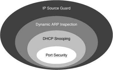
![]() The Cisco Catalyst Integrated Security capabilities provide campus security on the Cisco Catalyst switches using integrated tools, as shown in Figure 6-11.
The Cisco Catalyst Integrated Security capabilities provide campus security on the Cisco Catalyst switches using integrated tools, as shown in Figure 6-11.
-
 Port security prevents MAC flooding attacks.
 -
 DHCP snooping prevents client attacks on the DHCP server and switch.
 -
 Dynamic Address Resolution Protocol (ARP) inspection adds security to ARP using the DHCP snooping table to minimize the impact of ARP poisoning and spoofing attacks.
 -
 IP Source Guard (IPSG) prevents IP spoofing addresses using the DHCP snooping table.
![]() Port Security is covered in the MAC-based attack section of this chapter. DHCP snooping, DAI, and IP source guard can be used to prevent spoof attacks and are covered in depth in this section.
Port Security is covered in the MAC-based attack section of this chapter. DHCP snooping, DAI, and IP source guard can be used to prevent spoof attacks and are covered in depth in this section.
 DHCP Spoofing Attack
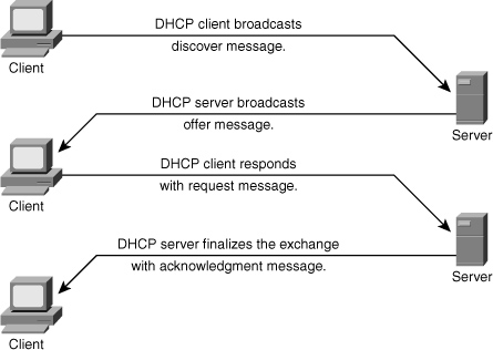
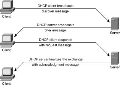
![]() DHCP is a protocol used to dynamically assign an IP address and default gateway among other configurations to a client in a network. DHCP is achieved through an exchange of protocol packets between the client and the DHCP server, as shown in Figure 6-12.
DHCP is a protocol used to dynamically assign an IP address and default gateway among other configurations to a client in a network. DHCP is achieved through an exchange of protocol packets between the client and the DHCP server, as shown in Figure 6-12.
![]() DHCP uses four messages to provide an IP address to a client:
DHCP uses four messages to provide an IP address to a client:
-
 DHCP discover broadcast from client
 -
 DHCP offer broadcast to client
 -
 DHCP unicast request from client
 -
 DHCP unicast acknowledge to client
![]() One of the ways that an attacker can gain access to network traffic is to spoof responses that would be sent by a valid DHCP server. The DHCP spoofing device replies to client DHCP requests. The legitimate server can reply also, but if the spoofing device is on the same segment as the client, its reply to the client might arrive first.
One of the ways that an attacker can gain access to network traffic is to spoof responses that would be sent by a valid DHCP server. The DHCP spoofing device replies to client DHCP requests. The legitimate server can reply also, but if the spoofing device is on the same segment as the client, its reply to the client might arrive first.
![]() The intruder’s DHCP reply offers an IP address and supporting information that designates the intruder as the default gateway or Domain Name System (DNS) server. For a gateway, the clients then forward packets to the attacking device, which in turn sends them to the desired destination. This is referred to as a man-in-the-middle attack, and it can go entirely undetected as the intruder intercepts the data flow through the network.
The intruder’s DHCP reply offers an IP address and supporting information that designates the intruder as the default gateway or Domain Name System (DNS) server. For a gateway, the clients then forward packets to the attacking device, which in turn sends them to the desired destination. This is referred to as a man-in-the-middle attack, and it can go entirely undetected as the intruder intercepts the data flow through the network.
![]() The following describes the DHCP spoof attack sequence:
The following describes the DHCP spoof attack sequence:
-
 Attacker hosts a rogue DHCP server off a switch port.
 -
 Client broadcasts a request for DHCP configuration information.
 -
 The rogue DHCP server responds before the legitimate DHCP server, assigning attacker-defined IP configuration information.
 -
 Host packets are redirected to the attacker’s address as it emulates a default gateway for the erroneous DHCP address provided to the client.
![]() A couple of scenarios can occur in a DHCP-enabled network. Attacker can cause a DoS attack by sending thousands of DHCP requests, as shown in Figure 6-13. The DHCP server does not have the capability to determine whether the request is genuine and therefore might end up exhausting all the available IP addresses. This results in a legitimate client not getting a IP address via DHCP.
A couple of scenarios can occur in a DHCP-enabled network. Attacker can cause a DoS attack by sending thousands of DHCP requests, as shown in Figure 6-13. The DHCP server does not have the capability to determine whether the request is genuine and therefore might end up exhausting all the available IP addresses. This results in a legitimate client not getting a IP address via DHCP.
![]() A second scenario can happen when the attacker attaches a DCHP server to the network and has it assume the role of the DHCP server for that segment. This enables the intruder to give out false DHCP information for the default gateway and domain name servers, which points clients to the hacker’s machine. This misdirection enables the hacker to become a man-in-the-middle and to gain access to confidential information, such as username and password pairs, while the end user is unaware of the attack.
A second scenario can happen when the attacker attaches a DCHP server to the network and has it assume the role of the DHCP server for that segment. This enables the intruder to give out false DHCP information for the default gateway and domain name servers, which points clients to the hacker’s machine. This misdirection enables the hacker to become a man-in-the-middle and to gain access to confidential information, such as username and password pairs, while the end user is unaware of the attack.
![]() The following describes the DHCP spoof attack sequence, as shown in Figure 6-13:
The following describes the DHCP spoof attack sequence, as shown in Figure 6-13:
-
 Attacker hosts a rogue DHCP server off a switch port.
 -
 Client broadcasts a request for DHCP configuration information.
 -
 The rogue DHCP server responds before the legitimate DHCP server, assigning attacker-defined IP configuration information.
 -
 Host packets are redirected to the attacker’s address as it emulates a default gateway for the erroneous DHCP address provided to the client.
![]() DHCP snooping can prevent these two types of attacks. DHCP snooping is a per-port security mechanism used to differentiate an untrusted switch port connected to an end user from a trusted switch port connected to a DHCP server or another switch. It can be enabled on a per-VLAN basis. DHCP snooping enables only authorized DHCP servers to respond to DHCP requests and to distribute network information to clients.
DHCP snooping can prevent these two types of attacks. DHCP snooping is a per-port security mechanism used to differentiate an untrusted switch port connected to an end user from a trusted switch port connected to a DHCP server or another switch. It can be enabled on a per-VLAN basis. DHCP snooping enables only authorized DHCP servers to respond to DHCP requests and to distribute network information to clients.
 DHCP Snooping
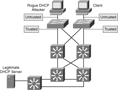
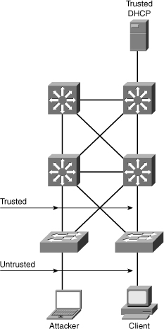
![]() DHCP snooping is a Cisco Catalyst feature that determines which switch ports can respond to DHCP requests. Ports are identified as trusted and untrusted. Trusted ports can source all DHCP messages, whereas untrusted ports can source requests only. Trusted ports host a DHCP server or can be an uplink toward the DHCP server, as shown in Figure 6-14. If a rogue device on an untrusted port attempts to send a DHCP response packet into the network, the port is shut down. This feature can be coupled with DHCP Option 82, in which switch information, such as the port ID of the DHCP request, can be inserted into the DHCP request packet.
DHCP snooping is a Cisco Catalyst feature that determines which switch ports can respond to DHCP requests. Ports are identified as trusted and untrusted. Trusted ports can source all DHCP messages, whereas untrusted ports can source requests only. Trusted ports host a DHCP server or can be an uplink toward the DHCP server, as shown in Figure 6-14. If a rogue device on an untrusted port attempts to send a DHCP response packet into the network, the port is shut down. This feature can be coupled with DHCP Option 82, in which switch information, such as the port ID of the DHCP request, can be inserted into the DHCP request packet.
![]() Untrusted ports are those not explicitly configured as trusted. A DHCP binding table is built for untrusted ports. Each entry contains the client MAC address, IP address, lease time, binding type, VLAN number, and port ID recorded as clients make DHCP requests. The table is then used to filter subsequent DHCP traffic. From a DHCP snooping perspective, untrusted access ports should not send any DHCP server responses, such as DHCPOFFER, DHCPACK, or DHCPNAK.
Untrusted ports are those not explicitly configured as trusted. A DHCP binding table is built for untrusted ports. Each entry contains the client MAC address, IP address, lease time, binding type, VLAN number, and port ID recorded as clients make DHCP requests. The table is then used to filter subsequent DHCP traffic. From a DHCP snooping perspective, untrusted access ports should not send any DHCP server responses, such as DHCPOFFER, DHCPACK, or DHCPNAK.
![]() To enable DHCP snooping, use the commands listed in Table 6-3.
To enable DHCP snooping, use the commands listed in Table 6-3.
|
|
|
|---|---|
|
|
|
|
|
|
|
|
|
|
|
|
|
|
|
|
|
|
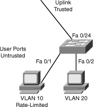
![]() Example 6-8 illustrates sample DHCP snooping configuration for a simple topology of an access layer switch in Figure 6-15.
Example 6-8 illustrates sample DHCP snooping configuration for a simple topology of an access layer switch in Figure 6-15.
switch(config)# ip dhcp snooping
switch(config)# ip dhcp snooping information option
switch(config)# ip dhcp snooping vlan 10,20
switch(config)# interface fastethernet 0/1
switch(config-if)# description Access Port
switch(config-if)# ip dhcp limit rate 5
switch(config)# interface fastethernet 0/24
switch(config-if)# description Uplink
switch(config-if)# switchport mode trunk
switch(config-if)# switchport trunk allowed vlan 10,20
switch(config-if)# ip dhcp snooping trust
![]() The show ip dhcp snooping family of commands is used to display information about the DHCP snooping configuration, as shown in Example 6-9.
The show ip dhcp snooping family of commands is used to display information about the DHCP snooping configuration, as shown in Example 6-9.
![]() In Example 6-9, DHCP snooping is configured for VLANs 10 and 20 and operational on both of them. Only ports that are trusted or that have a rate limit applied will be shown in the output. Interface f0/1 has its rate limited and is not trusted, whereas interface f0/24 does not have any rate limitation and is trusted. All the other ports are untrusted and do not have a rate limit. They are not displayed.
In Example 6-9, DHCP snooping is configured for VLANs 10 and 20 and operational on both of them. Only ports that are trusted or that have a rate limit applied will be shown in the output. Interface f0/1 has its rate limited and is not trusted, whereas interface f0/24 does not have any rate limitation and is trusted. All the other ports are untrusted and do not have a rate limit. They are not displayed.
switch# show ip dhcp snooping
Switch DHCP snooping is enabled
DHCP snooping is configured on following VLANs:
10,20
DHCP snooping is operational on following VLANs:
10,20
DHCP snooping is configured on the following L3 Interfaces:
Insertion of option 82 is enabled
  circuit-id default format: vlan-mod-port
  remote-id: 001a.e372.ab00 (MAC)
Option 82 on untrusted port is not allowed
Verification of hwaddr field is enabled
Verification of giaddr field is enabled
DHCP snooping trust/rate is configured on the following Interfaces:
Interface                    Trusted    Allow option    Rate limit (pps)
-----------------------     -------    ------------    ----------------
FastEthernet0/1             no         no               5
FastEthernet0/24            yes        yes              unlimited
 ARP Spoofing Attack
![]() In a normal ARP operation, a host sends a broadcast to determine the MAC address of a host with a particular IP address. The device at that IP address replies with its MAC address. The originating host caches the ARP response, using it to populate the destination Layer 2 header of packets sent to that IP address.
In a normal ARP operation, a host sends a broadcast to determine the MAC address of a host with a particular IP address. The device at that IP address replies with its MAC address. The originating host caches the ARP response, using it to populate the destination Layer 2 header of packets sent to that IP address.
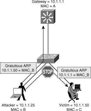
![]() By spoofing an ARP reply from a legitimate device with a gratuitous ARP, an attacking device appears to be the destination host sought by the senders. The ARP reply from the attacker causes the sender to store the MAC address of the attacking system in its ARP cache. All packets destined for those IP addresses are forwarded through the attacker system.
By spoofing an ARP reply from a legitimate device with a gratuitous ARP, an attacking device appears to be the destination host sought by the senders. The ARP reply from the attacker causes the sender to store the MAC address of the attacking system in its ARP cache. All packets destined for those IP addresses are forwarded through the attacker system.
![]() An ARP spoofing attack follows the sequence shown in Table 6-4, as illustrated in Figure 6-16.
An ARP spoofing attack follows the sequence shown in Table 6-4, as illustrated in Figure 6-16.
|
|
|
|---|---|
|
|
|
|
|
|
|
|
|
|
|
|
|
|
|
|
|
|
|
|
|
|
|
|
 Preventing ARP Spoofing Through Dynamic ARP Inspection
![]() ARP does not have any authentication. It is quite simple for a malicious user to spoof addresses by using tools such as ettercap, dsniff, and arpspoof to poison the ARP tables of other hosts on the same VLAN. In a typical attack, a malicious user can send unsolicited ARP replies (gratuitous ARP packets) to other hosts on the subnet with the attacker’s MAC address and the default gateway’s IP address. Frames intended for default gateways sent from hosts with poisoned ARP tables are sent to the hacker’s machine (enabling the packets to be sniffed) or an unreachable host as a DoS attack. ARP poisoning leads to various man-in-the-middle attacks, posing a security threat in the network.
ARP does not have any authentication. It is quite simple for a malicious user to spoof addresses by using tools such as ettercap, dsniff, and arpspoof to poison the ARP tables of other hosts on the same VLAN. In a typical attack, a malicious user can send unsolicited ARP replies (gratuitous ARP packets) to other hosts on the subnet with the attacker’s MAC address and the default gateway’s IP address. Frames intended for default gateways sent from hosts with poisoned ARP tables are sent to the hacker’s machine (enabling the packets to be sniffed) or an unreachable host as a DoS attack. ARP poisoning leads to various man-in-the-middle attacks, posing a security threat in the network.
![]() Dynamic ARP inspection helps prevent the man-in-the-middle attacks by not relaying invalid or gratuitous ARP replies out to other ports in the same VLAN, as shown in Figure 6-17. Dynamic ARP inspection intercepts all ARP requests and all replies on the untrusted ports. Each intercepted packet is verified for valid IP-to-MAC bindings that are gathered via DHCP snooping. Denied ARP packets are either dropped or logged by the switch for auditing, so ARP poisoning attacks are stopped. Incoming ARP packets on the trusted ports are not inspected. Dynamic ARP inspection can also rate-limit ARP requests from client ports to minimize port scanning mechanisms.
Dynamic ARP inspection helps prevent the man-in-the-middle attacks by not relaying invalid or gratuitous ARP replies out to other ports in the same VLAN, as shown in Figure 6-17. Dynamic ARP inspection intercepts all ARP requests and all replies on the untrusted ports. Each intercepted packet is verified for valid IP-to-MAC bindings that are gathered via DHCP snooping. Denied ARP packets are either dropped or logged by the switch for auditing, so ARP poisoning attacks are stopped. Incoming ARP packets on the trusted ports are not inspected. Dynamic ARP inspection can also rate-limit ARP requests from client ports to minimize port scanning mechanisms.
![]() To prevent ARP spoofing or “poisoning,” a switch must ensure that only valid ARP requests and responses are relayed. DAI prevents these attacks by intercepting and validating all ARP requests and responses. Each intercepted ARP reply is verified for valid MAC-address-to-IP-address bindings before it is forwarded to a PC to update the ARP cache. ARP replies coming from invalid devices are dropped.
To prevent ARP spoofing or “poisoning,” a switch must ensure that only valid ARP requests and responses are relayed. DAI prevents these attacks by intercepting and validating all ARP requests and responses. Each intercepted ARP reply is verified for valid MAC-address-to-IP-address bindings before it is forwarded to a PC to update the ARP cache. ARP replies coming from invalid devices are dropped.
![]() DAI determines the validity of an ARP packet based on a valid MAC-address-to-IP-address bindings database built by DHCP snooping. In addition, to handle hosts that use statically configured IP addresses, DAI can also validate ARP packets against user-configured ARP ACLs.
DAI determines the validity of an ARP packet based on a valid MAC-address-to-IP-address bindings database built by DHCP snooping. In addition, to handle hosts that use statically configured IP addresses, DAI can also validate ARP packets against user-configured ARP ACLs.
![]() To ensure that only valid ARP requests and responses are relayed, DAI takes these actions:
To ensure that only valid ARP requests and responses are relayed, DAI takes these actions:
-
 Forwards ARP packets received on a trusted interface without any checks
 -
 Intercepts all ARP packets on untrusted ports
 -
 Verifies that each intercepted packet has a valid IP-to-MAC address binding before forwarding packets that can update the local ARP cache
 -
 Drops and logs ARP packets with invalid IP-to-MAC address bindings
![]() Configure all access switch ports as untrusted and all switch ports connected to other switches as trusted. In this case, all ARP packets entering the network would be from an upstream distribution or core switch, bypassing the security check and requiring no further validation.
Configure all access switch ports as untrusted and all switch ports connected to other switches as trusted. In this case, all ARP packets entering the network would be from an upstream distribution or core switch, bypassing the security check and requiring no further validation.
![]() DAI can also be used to rate limit the ARP packets and then errdisable the interface if the rate is exceeded. Figure 6-18 shows the DAI recommended configuration.
DAI can also be used to rate limit the ARP packets and then errdisable the interface if the rate is exceeded. Figure 6-18 shows the DAI recommended configuration.
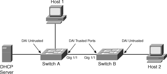
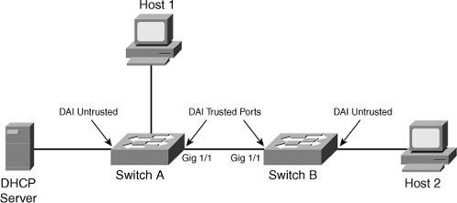
![]() To illustrate DAI operation in a multilayer switched network, consider the network shown in Figure 6-19 with two switches, Switches A and B. Host 1 is connected to Switch A, and Host 2 is connected to Switch B. The DHCP server is connected to Switch A. DHCP snooping is enabled on both Switch A and Switch B as a prerequisite for DAI. The inter-switch links are configured as DAI trusted ports, and the user ports are left in the default untrusted state.
To illustrate DAI operation in a multilayer switched network, consider the network shown in Figure 6-19 with two switches, Switches A and B. Host 1 is connected to Switch A, and Host 2 is connected to Switch B. The DHCP server is connected to Switch A. DHCP snooping is enabled on both Switch A and Switch B as a prerequisite for DAI. The inter-switch links are configured as DAI trusted ports, and the user ports are left in the default untrusted state.
![]() Example 6-10 shows the configuration and verification of the switches for DAI for the scenario in Figure 6-19. Assume that all the devices are in VLAN 10 in this scenario. (The switches connect to each other via uplink ports GigabitEthernet 1/1.)
Example 6-10 shows the configuration and verification of the switches for DAI for the scenario in Figure 6-19. Assume that all the devices are in VLAN 10 in this scenario. (The switches connect to each other via uplink ports GigabitEthernet 1/1.)
SwitchA# configure terminal
Enter configuration commands, one per line. End with CNTL/Z.
SwitchA(config)# ip arp inspection vlan 10
SwitchA(config)# interface gigabitEthernet 1/1
SwitchA(config-if)# ip arp inspection trust
SwitchA(config-if)# end
SwitchA#
SwitchB# configure terminal
Enter configuration commands, one per line. End with CNTL/Z.
SwitchB(config)# ip arp inspection vlan 10
SwitchB(config)# interface gigabitEthernet 1/1
SwitchB(config-if)# ip arp inspection trust
SwitchB(config-if)# end
SwitchB#
SwitchA# show ip arp inspection interfaces
Interface Trust State Rate (pps) Burst Interval
--------------- ----------- ---------- --------------
Gi1/1 Trusted None N/A
Gi1/2 Untrusted 15 1
Fa2/1 Untrusted 15 1
Fa2/2 Untrusted 15 1
Fa2/3 Untrusted 15 1
Fa2/4 Untrusted 15 1
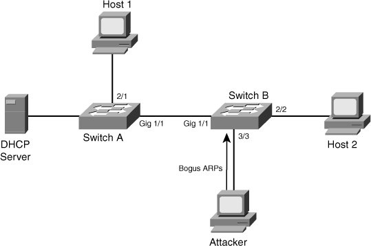
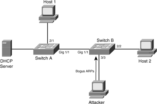
![]() Now if an attacker connects to Switch B, as shown in Figure 6-20, and tries to send a bogus ARP request, Switch B will detect it and drop the ARP request packet. The switch can also err-disable or shut down the port and send a log message to alert the administrator. DAI discards any ARP packets with invalid MAC address-to-IP address bindings.
Now if an attacker connects to Switch B, as shown in Figure 6-20, and tries to send a bogus ARP request, Switch B will detect it and drop the ARP request packet. The switch can also err-disable or shut down the port and send a log message to alert the administrator. DAI discards any ARP packets with invalid MAC address-to-IP address bindings.
![]() The error message displayed on the switch when such a security violation occurs is
The error message displayed on the switch when such a security violation occurs is
02:46:49: %SW_DAI-4-DHCP_SNOOPING_DENY: 1 Invalid ARPs (Req) on Fa3/3, vlan
10.([0001.0001.0001/10.10.10.1/0000.0000.0000/0.0.0.0/09:23:24 UTC Thu Nov 27
 2003])
![]() Table 6-5 describes the commands used to configure DAI on Cisco Catalyst switch.
Table 6-5 describes the commands used to configure DAI on Cisco Catalyst switch.
|
|
|
|---|---|
|
|
|
|
|
|
|
|
|
![]() It is generally advisable to configure all access switch ports as untrusted and to configure all uplink ports connected to other switches as trusted.
It is generally advisable to configure all access switch ports as untrusted and to configure all uplink ports connected to other switches as trusted.
 IP Spoofing and IP Source Guard
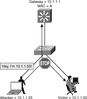
![]() IP spoofing can occur when the attack is impersonating as a legitimate host on the network, as shown in Figure 6-21. IP spoofing can result in unauthorized access or DoS attacks initiated by the attacker.
IP spoofing can occur when the attack is impersonating as a legitimate host on the network, as shown in Figure 6-21. IP spoofing can result in unauthorized access or DoS attacks initiated by the attacker.
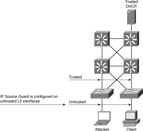
![]() IP Source Guard prevents a malicious host from attacking the network by hijacking its neighbor’s IP address. IP Source Guard provides per-port IP traffic filtering of the assigned source IP addresses at wire speed. It dynamically maintains per-port VLAN ACLs based on IP-to-MAC-to-switch port bindings. The binding table is populated either by the DHCP snooping feature or through static configuration of entries. IP Source Guard is typically deployed for untrusted switch ports in the access layer.
IP Source Guard prevents a malicious host from attacking the network by hijacking its neighbor’s IP address. IP Source Guard provides per-port IP traffic filtering of the assigned source IP addresses at wire speed. It dynamically maintains per-port VLAN ACLs based on IP-to-MAC-to-switch port bindings. The binding table is populated either by the DHCP snooping feature or through static configuration of entries. IP Source Guard is typically deployed for untrusted switch ports in the access layer.
![]() IP Source Guard works closely with DHCP snooping. This feature can be enabled on a DHCP snooping untrusted Layer 2 port to prevent IP address spoofing, as shown in Figure 6-22. To start, all IP traffic on the port is blocked except for DHCP packets captured by the DHCP snooping process.
IP Source Guard works closely with DHCP snooping. This feature can be enabled on a DHCP snooping untrusted Layer 2 port to prevent IP address spoofing, as shown in Figure 6-22. To start, all IP traffic on the port is blocked except for DHCP packets captured by the DHCP snooping process.
![]() When a client receives a valid IP address from the DHCP server, or when a static IP source binding is configured by the user, a per-port and VLAN Access Control List (PVACL) is installed on the port.
When a client receives a valid IP address from the DHCP server, or when a static IP source binding is configured by the user, a per-port and VLAN Access Control List (PVACL) is installed on the port.
![]() This process restricts the client IP traffic to those source IP addresses configured in the binding; any IP traffic with a source IP address other than that in the IP source binding is filtered out. This filtering limits a host’s capability to attack the network by claiming a neighbor host’s IP address.
This process restricts the client IP traffic to those source IP addresses configured in the binding; any IP traffic with a source IP address other than that in the IP source binding is filtered out. This filtering limits a host’s capability to attack the network by claiming a neighbor host’s IP address.
![]() IP Source Guard supports only the Layer 2 port, including both access and trunk. For each untrusted Layer 2 port, two levels of IP traffic security filtering exist:
IP Source Guard supports only the Layer 2 port, including both access and trunk. For each untrusted Layer 2 port, two levels of IP traffic security filtering exist:
-
 Source IP address filter: IP traffic is filtered based on its source IP address. Only IP traffic with a source IP address that matches the IP source binding entry is permitted.
 An IP source address filter is changed when a new IP source entry binding is created or deleted on the port. The PVACL will be recalculated and reapplied in the hardware to reflect the IP source binding change. By default, if the IP filter is enabled without any IP source binding on the port, a default PVACL that denies all IP traffic is installed on the port. Similarly, when the IP filter is disabled, any IP source filter PVACL is removed from the interface.
 -
 Source IP and MAC address filter: IP traffic is filtered based on its source IP address in addition to its MAC address; only IP traffic with source IP and MAC addresses that match the IP source binding entry are permitted.
Configuring IPSG
![]() IPSG requires that DHCP snooping be enabled on the required VLAN to enable automated IP source bindings.
IPSG requires that DHCP snooping be enabled on the required VLAN to enable automated IP source bindings.
![]() Table 6-6 describes the procedure for enabling IP Source Guard.
Table 6-6 describes the procedure for enabling IP Source Guard.
|
|
| |
|---|---|---|
|
|
|
|
|
|
|
|
|
|
|
|
|
|
|
|
|
|
|
|
![]() For more information on how to configure IPSG on CatOS-based Catalyst 6500 switches, refer to the “Configuring DHCP Snooping and IP Source Guard” section in the software configuration guide on Cisco.com.
For more information on how to configure IPSG on CatOS-based Catalyst 6500 switches, refer to the “Configuring DHCP Snooping and IP Source Guard” section in the software configuration guide on Cisco.com.
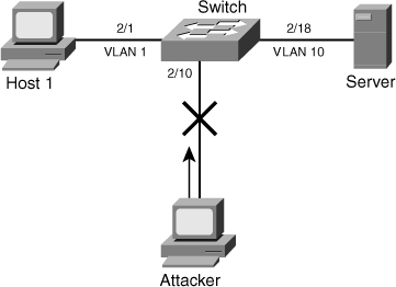
![]() Figure 6-23 shows a scenario in which a workstation using DHCP for acquiring IP addresses and a server that uses a static IP address connect to a Catalyst switch. Example 6-11 shows configuration and verification of IPSG for the scenario in Figure 6-23.
Figure 6-23 shows a scenario in which a workstation using DHCP for acquiring IP addresses and a server that uses a static IP address connect to a Catalyst switch. Example 6-11 shows configuration and verification of IPSG for the scenario in Figure 6-23.
Switch# configure terminal
Enter configuration commands, one per line. End with CNTL/Z.
Switch(config)# ip dhcp snooping
Switch(config)# ip dhcp snooping vlan 1,10
Switch(config)# ip dhcp snooping verify mac-address
Switch(config)# ip source binding 0000.000a.000b vlan 10 10.1.10.11 interface
 Fa2/18
Switch(config)# interface fastethernet 2/1
Switch(config-if)# switchport
Switch(config-if)# switchport mode access
Switch(config-if)# switchport port-security
Switch(config-if)# ip verify source vlan dhcp-snooping port-security
Switch(config)# interface fastethernet 2/18
Switch(config-if)# switchport
Switch(config-if)# switchport mode access
Switch(config-if)# switchport port-security
Switch(config-if)# ip verify source vlan dhcp-snooping port-security
Switch(config-if)# end
Switch# show ip source binding
MacAddress          IpAddress     Lease(sec)  Type           VLAN  Interface
------------------  ------------  ----------  -------------  ----  ----------
00:02:B3:3F:3B:99   10.1.1.11     6522        dhcp-snooping   1    FastEthernet2/1
00:00:00:0A:00:0B   10.1.10.11    infinite    static         10    FastEthernet2/18
Switch# show ip verify source
Interface  Filter-type  Filter-mode   IP-address       Mac-address         Vlan
---------  -----------  -----------  ---------------  -----------------  ----------
Fa2/1       ip-mac       active        10.1.1.11         00:02:B3:3F:3B:99  1
Fa2/18      ip-mac       active        10.1.10.11        00:00:00:0a:00:0b  10
![]() Figure 6-24 shows that an attacker is connected to interface 2/10 and is trying to spoof the IP address of the server. The Catalyst switch detects and drops the packets in the hardware path. The Catalyst switch also provides an error message to indicate the violation.
Figure 6-24 shows that an attacker is connected to interface 2/10 and is trying to spoof the IP address of the server. The Catalyst switch detects and drops the packets in the hardware path. The Catalyst switch also provides an error message to indicate the violation.
![]() IPSG is an essential security feature to prevent IP address spoof attacks at the Layer 2 level. Recommended practice is to enable IPSG on access layer switches in a multilayer switched network.
IPSG is an essential security feature to prevent IP address spoof attacks at the Layer 2 level. Recommended practice is to enable IPSG on access layer switches in a multilayer switched network.
| Note |
|







0 comments
Post a Comment