
Securing the campus infrastructure is as important as designing a highly available network. If security is compromised, serious impact to business can occur.
![]() This chapter defines the potential vulnerabilities related to VLANs that can occur within a network. After the vulnerabilities are identified, solutions for each vulnerability are discussed, and configuration commands are defined.
This chapter defines the potential vulnerabilities related to VLANs that can occur within a network. After the vulnerabilities are identified, solutions for each vulnerability are discussed, and configuration commands are defined.
![]() This chapter also discusses port security for denial of MAC spoofing and MAC flooding, and using private VLANs (PVLAN) and VLAN access control lists (VACL) to control VLAN traffic. VLAN hopping, Dynamic Host Control Protocol (DHCP) spoofing, Address Resolution Protocol (ARP) spoofing, and Spanning Tree Protocol (STP) attacks are also explained. This chapter also discusses potential problems, resulting solutions, and the method to secure the switch access with use of vty access control lists (ACL), and implementing Secure Shell Protocol (SSH) for secure Telnet access.
This chapter also discusses port security for denial of MAC spoofing and MAC flooding, and using private VLANs (PVLAN) and VLAN access control lists (VACL) to control VLAN traffic. VLAN hopping, Dynamic Host Control Protocol (DHCP) spoofing, Address Resolution Protocol (ARP) spoofing, and Spanning Tree Protocol (STP) attacks are also explained. This chapter also discusses potential problems, resulting solutions, and the method to secure the switch access with use of vty access control lists (ACL), and implementing Secure Shell Protocol (SSH) for secure Telnet access.
![]() This chapter concludes with a description of tools used to monitor, analyze, and troubleshoot switch performance, connectivity, and security issues.
This chapter concludes with a description of tools used to monitor, analyze, and troubleshoot switch performance, connectivity, and security issues.
 Switch Security Fundamentals
![]() Much industry attention surrounds security attacks from outside the walls of an organization and at the upper Open Systems Interconnection (OSI) layers. Network security often focuses on edge routing devices and the filtering of packets based on Layer 3 and Layer 4 headers, ports, stateful packet inspection, and so forth. This includes all issues surrounding Layer 3 and above, as traffic makes its way into the campus network from the Internet. Campus access devices and Layer 2 communication are left largely unconsidered in most security discussions, and there is lack of security at this layer.
Much industry attention surrounds security attacks from outside the walls of an organization and at the upper Open Systems Interconnection (OSI) layers. Network security often focuses on edge routing devices and the filtering of packets based on Layer 3 and Layer 4 headers, ports, stateful packet inspection, and so forth. This includes all issues surrounding Layer 3 and above, as traffic makes its way into the campus network from the Internet. Campus access devices and Layer 2 communication are left largely unconsidered in most security discussions, and there is lack of security at this layer.
![]() The default state of networking equipment highlights this focus on external protection and internal open communication. Firewalls, placed at the organizational borders, arrive in a secure operational mode and do not enable communication until configured to do so. Routers and switches that are internal to an organization and designed to accommodate communication, delivering needful campus traffic, have a default operational mode that forwards all traffic unless configured otherwise. Their function as devices that facilitate communication often results in minimal security configuration and renders them targets for malicious attacks. If an attack is launched at Layer 2 on an internal campus device, the rest of the network can be quickly compromised, often without detection. Also, non-malicious user intentions can also result in network disruption. Although activities such as a user plugging in a switch or a hub to a data port or configuring his or her laptop as a DHCP server are not intended to be malicious, nevertheless they can still result in network disruptions.
The default state of networking equipment highlights this focus on external protection and internal open communication. Firewalls, placed at the organizational borders, arrive in a secure operational mode and do not enable communication until configured to do so. Routers and switches that are internal to an organization and designed to accommodate communication, delivering needful campus traffic, have a default operational mode that forwards all traffic unless configured otherwise. Their function as devices that facilitate communication often results in minimal security configuration and renders them targets for malicious attacks. If an attack is launched at Layer 2 on an internal campus device, the rest of the network can be quickly compromised, often without detection. Also, non-malicious user intentions can also result in network disruption. Although activities such as a user plugging in a switch or a hub to a data port or configuring his or her laptop as a DHCP server are not intended to be malicious, nevertheless they can still result in network disruptions.
![]() Many security features are available for switches and routers, but they must be enabled to be effective. As with Layer 3, where security had to be tightened on devices within the campus as malicious activity that compromised this layer increased; now security measures must be taken to guard against malicious activity at Layer 2. A new security focus centers on attacks launched by maliciously leveraging normal Layer 2 switch operations. Security features exist to protect switches and Layer 2 operations. However, as with access control lists (ACL) for upper-layer security, a policy must be established and appropriate features configured to protect against potential malicious acts while maintaining daily network operations.
Many security features are available for switches and routers, but they must be enabled to be effective. As with Layer 3, where security had to be tightened on devices within the campus as malicious activity that compromised this layer increased; now security measures must be taken to guard against malicious activity at Layer 2. A new security focus centers on attacks launched by maliciously leveraging normal Layer 2 switch operations. Security features exist to protect switches and Layer 2 operations. However, as with access control lists (ACL) for upper-layer security, a policy must be established and appropriate features configured to protect against potential malicious acts while maintaining daily network operations.
Security Infrastructure Services
![]() Security is an infrastructure service that increases the integrity of the network by protecting network resources and users from internal and external threats. Without a full understanding of the threats involved, network security deployments tend to be incorrectly configured, too focused on security devices, or lacking appropriate threat-response options.
Security is an infrastructure service that increases the integrity of the network by protecting network resources and users from internal and external threats. Without a full understanding of the threats involved, network security deployments tend to be incorrectly configured, too focused on security devices, or lacking appropriate threat-response options.
![]() You can evaluate and apply security on a module-by-module basis within the Cisco Enterprise Architecture, as shown in Figure 6-1.
You can evaluate and apply security on a module-by-module basis within the Cisco Enterprise Architecture, as shown in Figure 6-1.


![]() The following are some recommended-practice security considerations for each module:
The following are some recommended-practice security considerations for each module:
- The campus core layer in the campus infrastructure module switches packets as quickly as possible. It should not perform any security functions because these would slow down packet switching.
- The building distribution layer performs packet filtering to keep unnecessary traffic from the campus core layer. Packet filtering at the building distribution layer is a security function because it prevents some unwanted access to other modules. Given that switches in this layer are usually Layer 3-aware multilayer switches, the building distribution layer is often the first location that can filter based on network layer information.
- At the building access layer, access can be controlled at the port level with respect to the data link layer information (for example, MAC addresses).
- The server farm module provides application services to end users and devices. Given the high degree of access that most employees have to these servers, they often become the primary target of internally originated attacks. Use host- and network-based intrusion prevention systems (IPS), private VLANs, and access control to provide a more comprehensive response to attacks. Onboard IDS within multilayer switches can inspect traffic flows on the server farm module.
- The server farm module typically includes a network management system that securely manages all devices and hosts within the enterprise architecture. Syslog provides important information regarding security violations and configuration changes by logging security-related events (authentication and so on). Other servers, including an authentication, authorization, and accounting (AAA) security server, can work in combination with the one-time password (OTP) server to provide a high level of security to all local and remote users. AAA and OTP authentication reduce the likelihood of a successful password attack.
![]() Several reasons exist for strong protection of the campus infrastructure, including security functions in each individual element of the enterprise campus:
Several reasons exist for strong protection of the campus infrastructure, including security functions in each individual element of the enterprise campus:
![]() Relying on the security that has been established at the enterprise edge fails as soon as security there is compromised. Several layers of security increase the protection of the enterprise campus, where usually the most strategic assets reside.
Relying on the security that has been established at the enterprise edge fails as soon as security there is compromised. Several layers of security increase the protection of the enterprise campus, where usually the most strategic assets reside.
![]() If the enterprise allows visitors into its buildings, potentially an attacker can gain physical access to devices in the enterprise campus. Relying on physical security is not enough.
If the enterprise allows visitors into its buildings, potentially an attacker can gain physical access to devices in the enterprise campus. Relying on physical security is not enough.
![]() Often, external access does not stop at the enterprise edge. Applications require at least an indirect access to the enterprise campus resources, requiring strong security.
Often, external access does not stop at the enterprise edge. Applications require at least an indirect access to the enterprise campus resources, requiring strong security.
Unauthorized Access by Rogue Devices
![]() Rogue access comes in several forms, as shown in Figure 6-2. For example, because unauthorized rogue access points are inexpensive and readily available, employees sometimes plug them into existing LANs and build ad hoc wireless networks without IT department knowledge or consent. These rogue access points can be a serious breach of network security because they can be plugged into a network port behind the corporate firewall. Because employees generally do not enable any security settings on the rogue access point, it is easy for unauthorized users to use the access point to intercept network traffic and hijack client sessions.
Rogue access comes in several forms, as shown in Figure 6-2. For example, because unauthorized rogue access points are inexpensive and readily available, employees sometimes plug them into existing LANs and build ad hoc wireless networks without IT department knowledge or consent. These rogue access points can be a serious breach of network security because they can be plugged into a network port behind the corporate firewall. Because employees generally do not enable any security settings on the rogue access point, it is easy for unauthorized users to use the access point to intercept network traffic and hijack client sessions.


![]() Malicious rogue access points, although much less common than employee-installed rogue access points, are also a security concern. These rogue access points create an unsecured wireless LAN connection that puts the entire wired network at risk. Malicious rogues present an even greater risk and challenge because they are intentionally hidden from physical and network view by not broadcasting the SSID.
Malicious rogue access points, although much less common than employee-installed rogue access points, are also a security concern. These rogue access points create an unsecured wireless LAN connection that puts the entire wired network at risk. Malicious rogues present an even greater risk and challenge because they are intentionally hidden from physical and network view by not broadcasting the SSID.
![]() To mitigate Spanning Tree Protocol (STP) manipulation, use the root guard and the BPDU guard enhancement commands to enforce the placement of the root bridge in the network and to enforce the STP domain borders. The root guard feature is designed to provide a way to enforce the root bridge placement in the network. The STP bridge protocol data unit (BPDU) guard is designed to enable network designers to keep the active network topology predictable. Although the BPDU guard might seem unnecessary, given that the administrator can set the bridge priority to zero, there is still no guarantee that it will be elected as the root bridge because there might be a bridge with priority zero and a lower bridge ID. A BPDU guard is best deployed toward user-facing ports to prevent unauthorized switches from being attached to the network by an attacker.
To mitigate Spanning Tree Protocol (STP) manipulation, use the root guard and the BPDU guard enhancement commands to enforce the placement of the root bridge in the network and to enforce the STP domain borders. The root guard feature is designed to provide a way to enforce the root bridge placement in the network. The STP bridge protocol data unit (BPDU) guard is designed to enable network designers to keep the active network topology predictable. Although the BPDU guard might seem unnecessary, given that the administrator can set the bridge priority to zero, there is still no guarantee that it will be elected as the root bridge because there might be a bridge with priority zero and a lower bridge ID. A BPDU guard is best deployed toward user-facing ports to prevent unauthorized switches from being attached to the network by an attacker.
Layer 2 Attack Categories
![]() Layer 2 malicious attacks are typically initiated by devices directly connected to the campus network infrastructure. The attacks can originate from a physical rogue device placed on the network for malicious purposes. The attack also can come from an external intrusion that takes control of and launches attacks from a trusted device. In either case, the network sees all traffic as originating from a legitimate connected device.
Layer 2 malicious attacks are typically initiated by devices directly connected to the campus network infrastructure. The attacks can originate from a physical rogue device placed on the network for malicious purposes. The attack also can come from an external intrusion that takes control of and launches attacks from a trusted device. In either case, the network sees all traffic as originating from a legitimate connected device.
![]() Attacks launched against switches and at Layer 2 can be grouped as follows:
Attacks launched against switches and at Layer 2 can be grouped as follows:
![]() These attack methods and steps to mitigate these threats are discussed in more detail in this chapter.
These attack methods and steps to mitigate these threats are discussed in more detail in this chapter.
![]() Table 6-1 describes attack methods and the steps to mitigation.
Table 6-1 describes attack methods and the steps to mitigation.
Understanding and Protecting Against MAC Layer Attack
![]() A common Layer 2 or switch attack is MAC flooding, resulting in a switch’s CAM table overflow, which causes flooding of regular data frames out all switch ports. This attack can be launched for the malicious purpose of collecting a broad sample of traffic or as a denial of service (DoS) attack.
A common Layer 2 or switch attack is MAC flooding, resulting in a switch’s CAM table overflow, which causes flooding of regular data frames out all switch ports. This attack can be launched for the malicious purpose of collecting a broad sample of traffic or as a denial of service (DoS) attack.
![]() A switch’s CAM tables are limited in size and therefore can contain only a limited number of entries at any one time. A network intruder can maliciously flood a switch with a large number of frames from a range of invalid source MAC addresses. If enough new entries are made before old ones expire, new valid entries will not be accepted. Then, when traffic arrives at the switch for a legitimate device located on one of the switch ports that could not create a CAM table entry, the switch must flood frames to that address out all ports. This has two adverse effects:
A switch’s CAM tables are limited in size and therefore can contain only a limited number of entries at any one time. A network intruder can maliciously flood a switch with a large number of frames from a range of invalid source MAC addresses. If enough new entries are made before old ones expire, new valid entries will not be accepted. Then, when traffic arrives at the switch for a legitimate device located on one of the switch ports that could not create a CAM table entry, the switch must flood frames to that address out all ports. This has two adverse effects:
- The switch traffic forwarding is inefficient and voluminous and could potentially slow down the network for all users.
- An intruding device can be connected to any switch port and capture traffic not normally seen on that port.
![]() If the attack is launched before the beginning of the day, the MAC address table (also referred to as Content Addressable Memory [CAM] table) would be full when the majority of devices are powered on. Then frames from those legitimate devices cannot create MAC address table entries as they power on. If this represents a large number of network devices, the number of MAC addresses flooded with traffic will be high, and any switch port will carry flooded frames from a large number of devices.
If the attack is launched before the beginning of the day, the MAC address table (also referred to as Content Addressable Memory [CAM] table) would be full when the majority of devices are powered on. Then frames from those legitimate devices cannot create MAC address table entries as they power on. If this represents a large number of network devices, the number of MAC addresses flooded with traffic will be high, and any switch port will carry flooded frames from a large number of devices.
![]() If the initial flood of invalid MAC address table entries is a one-time event, the switch eventually ages out older, invalid MAC address table entries, allowing new, legitimate devices to create entries. Traffic flooding ceases and might never be detected, even though the intruder might have captured a significant amount of data from the network.
If the initial flood of invalid MAC address table entries is a one-time event, the switch eventually ages out older, invalid MAC address table entries, allowing new, legitimate devices to create entries. Traffic flooding ceases and might never be detected, even though the intruder might have captured a significant amount of data from the network.
![]() As Figure 6-3 shows, MAC flooding occurs in this progression; the following describes MAC flooding attack progression.
As Figure 6-3 shows, MAC flooding occurs in this progression; the following describes MAC flooding attack progression.


Suggested Mitigation for MAC Flooding Attacks
![]() To prevent MAC Address flooding, port security can be used. Configure port security to define the number of MAC addresses allowed on a given port. Port security can also specify what MAC address is allowed on a given port. Port security is described in the following section.
To prevent MAC Address flooding, port security can be used. Configure port security to define the number of MAC addresses allowed on a given port. Port security can also specify what MAC address is allowed on a given port. Port security is described in the following section.
Port Security
![]() Port security is a feature supported on Cisco Catalyst switches that restricts a switch port to a specific set or number of MAC addresses. Those addresses can be learned dynamically or configured statically. The port then provides access to frames from only those addresses. If, however, the number of addresses is limited to four but no specific MAC addresses are configured, the port enables any four MAC addresses to be learned dynamically, and port access is limited to those four dynamically learned addresses.
Port security is a feature supported on Cisco Catalyst switches that restricts a switch port to a specific set or number of MAC addresses. Those addresses can be learned dynamically or configured statically. The port then provides access to frames from only those addresses. If, however, the number of addresses is limited to four but no specific MAC addresses are configured, the port enables any four MAC addresses to be learned dynamically, and port access is limited to those four dynamically learned addresses.
![]() A port security feature called sticky learning, available on some switch platforms, combines the features of dynamically learned and statically configured addresses. When this feature is configured on an interface, the interface converts dynamically learned addresses to sticky secure addresses. This adds them to the running configuration as if they were configured using the switchport port-security mac-address interface command.
A port security feature called sticky learning, available on some switch platforms, combines the features of dynamically learned and statically configured addresses. When this feature is configured on an interface, the interface converts dynamically learned addresses to sticky secure addresses. This adds them to the running configuration as if they were configured using the switchport port-security mac-address interface command.
Port Security Scenario 1
![]() Imagine five individuals whose laptops are allowed to connect to a specific switch port when they visit an area of the building. You want to restrict switch port access to the MAC addresses of those five laptops and allow no addresses to be learned dynamically on that port.
Imagine five individuals whose laptops are allowed to connect to a specific switch port when they visit an area of the building. You want to restrict switch port access to the MAC addresses of those five laptops and allow no addresses to be learned dynamically on that port.
![]() Table 6-2 describes the process that can achieve the desired results for this scenario.
Table 6-2 describes the process that can achieve the desired results for this scenario.
|
|
| |
|---|---|---|
|
|
|
|
|
|
|
|
|
|
|
|
|
|
|
|
Port Security Scenario 2
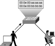
![]() In this scenario, an attacker enables a hacking tool leading to the attacker’s rogue device to flood switch CAM tables with bogus MACs, which fills up the MAC address table, as shown in Figure 6-4. When the MAC address table is full, it turns the VLAN into a hub and floods all unicast frames.
In this scenario, an attacker enables a hacking tool leading to the attacker’s rogue device to flood switch CAM tables with bogus MACs, which fills up the MAC address table, as shown in Figure 6-4. When the MAC address table is full, it turns the VLAN into a hub and floods all unicast frames.
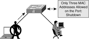
![]() To prevent this attack, Figure 6-5 shows that port security is configured on the untrusted user ports. Enabling port security limits MAC flooding attacks and locks down the port. Port security also sets an SNMP trap for alerting to any violation. Port security allows the frames from already secured MAC address below the maximum number of MAC addresses enabled on that port, and any frame with new MAC address over the limit are dropped.
To prevent this attack, Figure 6-5 shows that port security is configured on the untrusted user ports. Enabling port security limits MAC flooding attacks and locks down the port. Port security also sets an SNMP trap for alerting to any violation. Port security allows the frames from already secured MAC address below the maximum number of MAC addresses enabled on that port, and any frame with new MAC address over the limit are dropped.
Configuring Port Security
![]() Here are the steps to set up port security to limit switch port access to a finite number and a specific set of end-device MAC addresses.
Here are the steps to set up port security to limit switch port access to a finite number and a specific set of end-device MAC addresses.
![]() To configure port security, follow these steps:
To configure port security, follow these steps:
|
|
|
|
|
|
|
|
|
|
|
|
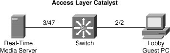
![]() Figure 6-6 depicts an access layer Catalyst 4500 switch scenario. A real-time media server plugs in to switch port 3/47. The switch port needs port security to prevent any unauthorized devices from plugging into the same port. The administrator has configured preferential QoS policies based on all traffic received on the port and other security ACLs. The network administrator requirement is not to shut down the port of the server but rather to restrict the port to only the authorized MAC address. In addition, the network administrator configures the switch to shut down port 2/2 in the guest lobby if any unauthorized workstation plugs into that port.
Figure 6-6 depicts an access layer Catalyst 4500 switch scenario. A real-time media server plugs in to switch port 3/47. The switch port needs port security to prevent any unauthorized devices from plugging into the same port. The administrator has configured preferential QoS policies based on all traffic received on the port and other security ACLs. The network administrator requirement is not to shut down the port of the server but rather to restrict the port to only the authorized MAC address. In addition, the network administrator configures the switch to shut down port 2/2 in the guest lobby if any unauthorized workstation plugs into that port.
![]() Example 6-1 shows the configuration for this scenario.
Example 6-1 shows the configuration for this scenario.
4503(config-if)# switchport
4503(config-if)# switchport mode access
4503(config-if)# switchport port-security
4503(config-if)# switchport port-security mac-address 0000.0000.0008
4503(config-if)# switchport port-security maximum 1
4503(config-if)# switchport port-security aging static
4503(config-if)# switchport port-security violation restrict
4503(config)# interface FastEthernet 2/2
4503(config-if)# switchport
4503(config-if)# switchport mode access
4503(config-if)# switchport port-security
4503(config-if)# switchport port-security mac-address 0000.0000.1118
4503(config-if)# switchport port-security maximum 1
4503(config-if)# switchport port-security aging static
4503(config-if)# switchport port-security violation shutdown
Caveats to Port Security Configuration Steps
Verifying Port Security
![]() The show port-security command can be used to verify the ports on which port security has been enabled, as shown in Example 6-2. It also displays count information and security actions to be taken per interface.
The show port-security command can be used to verify the ports on which port security has been enabled, as shown in Example 6-2. It also displays count information and security actions to be taken per interface.
![]() The full command syntax is as follows:
The full command syntax is as follows:
show port-security [interface intf_id] [address]
Secure Port MaxSecureAddr CurrentAddr SecurityViolation Security Action
(Count) (Count) (Count)
------------------------------------------------------------------------
Fa0/1 2 1 0 Restrict
------------------------------------------------------------------------
Total Addresses in System (excluding one mac per port) : 0
Max Addresses limit in System (excluding one mac per port) : 6144
![]() Arguments are provided to view port security status by interface or view the addresses associated with port security on all interfaces.
Arguments are provided to view port security status by interface or view the addresses associated with port security on all interfaces.
![]() Use the interface argument to provide output for a specific interface, as shown in Example 6-3.
Use the interface argument to provide output for a specific interface, as shown in Example 6-3.
Port Security : Enabled
Port Status : Secure-up
Violation Mode : Restrict
Aging Time : 60 mins
Aging Type : Inactivity
SecureStatic Address Aging : Enabled
Maximum MAC Addresses : 2
Total MAC Addresses : 1
Configured MAC Addresses : 0
Sticky MAC Addresses : 0
Last Source Address:Vlan : 001b.d513.2ad2:5
Security Violation Count : 0
![]() Use the address argument to display MAC address table security information, as shown in Example 6-4. The remaining age column is populated only when specifically configured for a given interface.
Use the address argument to display MAC address table security information, as shown in Example 6-4. The remaining age column is populated only when specifically configured for a given interface.
Secure Mac Address Table
------------------------------------------------------------------------
Vlan Mac Address Type Ports Remaining Age
(mins)
---- ----------- ---- ----- -------------
2 001b.d513.2ad2 SecureDynamic Fa0/1 60 (I)
------------------------------------------------------------------------
Total Addresses in System (excluding one mac per port) : 0
Max Addresses limit in System (excluding one mac per port) : 6144
Port Security with Sticky MAC Addresses
![]() Port security can mitigate spoofing attacks by limiting access through each switch port to a single MAC address. This prevents intruders from using multiple MAC addresses over a short time period but does not limit port access to a specific MAC address. The most restrictive port security implementation would specify the exact MAC address of the single device that is to gain access through each port. Implementing this level of security, however, requires considerable administrative overhead.
Port security can mitigate spoofing attacks by limiting access through each switch port to a single MAC address. This prevents intruders from using multiple MAC addresses over a short time period but does not limit port access to a specific MAC address. The most restrictive port security implementation would specify the exact MAC address of the single device that is to gain access through each port. Implementing this level of security, however, requires considerable administrative overhead.
![]() Port security has a sticky MAC addresses feature that can limit switch port access to a single, specific MAC address without the network administrator having to gather the MAC address of every legitimate device and manually associate it with a particular switch port.
Port security has a sticky MAC addresses feature that can limit switch port access to a single, specific MAC address without the network administrator having to gather the MAC address of every legitimate device and manually associate it with a particular switch port.
![]() When sticky MAC addresses are used, the switch port converts dynamically learned MAC addresses to sticky MAC addresses and subsequently adds them to the running configuration as if they were static entries for a single MAC address to be allowed by port security. Sticky secure MAC addresses will be added to the running configuration but will not become part of the startup configuration file unless the running configuration is copied to the startup configuration after addresses have been learned. If they are saved in the startup configuration, they will not have to be relearned upon switch reboot, and this provides a higher level of network security.
When sticky MAC addresses are used, the switch port converts dynamically learned MAC addresses to sticky MAC addresses and subsequently adds them to the running configuration as if they were static entries for a single MAC address to be allowed by port security. Sticky secure MAC addresses will be added to the running configuration but will not become part of the startup configuration file unless the running configuration is copied to the startup configuration after addresses have been learned. If they are saved in the startup configuration, they will not have to be relearned upon switch reboot, and this provides a higher level of network security.
| Note |
|
![]() The interface level configuration command that follows converts all dynamic port-security learned MAC addresses to sticky secure MAC addresses.
The interface level configuration command that follows converts all dynamic port-security learned MAC addresses to sticky secure MAC addresses.
switchport port-security mac-address sticky
![]() This command cannot be used on ports where voice VLANs are configured. Example 6-5 shows the configuration and verification of the sticky MAC address feature of port security.
This command cannot be used on ports where voice VLANs are configured. Example 6-5 shows the configuration and verification of the sticky MAC address feature of port security.
interface FastEthernet0/1
switchport access vlan 2
switchport mode access
switchport port-security maximum 2
switchport port-security
switchport port-security violation restrict
switchport port-security mac-address sticky
switchport port-security mac-address sticky 001b.d513.2ad2
switch# show port-security address
Secure Mac Address Table
------------------------------------------------------------------------
Vlan Mac Address Type Ports Remaining Age
(mins)
---- ----------- ---- ----- -------------
2 001b.d513.2ad2 SecureSticky Fa0/1 -
Blocking Unicast Flooding on Desired Ports
![]() By default, switches flood packets with unknown destination MAC addresses to all ports in the same VLAN as the received port’s VLAN. Some ports do not require flooding. For example, a port that has only manually assigned MAC addresses and that does not have a network device connected to that port other than the configured MAC address does not need to receive flooded packets. In addition, a port security–enabled port with a configured secure MAC address or port does not need to receive unknown unicast flooding if the port has already learned the maximum number of MAC addresses. If the network exhibits asymmetrical routing, excessive unicast flooding can occur and might cause all the devices in that VLAN to suffer as they receive the unneeded traffic. With asymmetrical routing, transmit and receive packets follow different paths between a host and the destination device. For more information about asymmetrical routing, see the following technical document at Cisco.com: “Unicast Flooding in Switched Campus Networks,” Document ID: 23563:
By default, switches flood packets with unknown destination MAC addresses to all ports in the same VLAN as the received port’s VLAN. Some ports do not require flooding. For example, a port that has only manually assigned MAC addresses and that does not have a network device connected to that port other than the configured MAC address does not need to receive flooded packets. In addition, a port security–enabled port with a configured secure MAC address or port does not need to receive unknown unicast flooding if the port has already learned the maximum number of MAC addresses. If the network exhibits asymmetrical routing, excessive unicast flooding can occur and might cause all the devices in that VLAN to suffer as they receive the unneeded traffic. With asymmetrical routing, transmit and receive packets follow different paths between a host and the destination device. For more information about asymmetrical routing, see the following technical document at Cisco.com: “Unicast Flooding in Switched Campus Networks,” Document ID: 23563:
- www.cisco.com/en/US/products/hw/switches/ps700/products_tech_note09186a00801d0808.shtml
![]() The unicast flood-blocking feature prevents the forwarding of unicast flood traffic on unnecessary ports. Restricting the amount of traffic on a per-port basis adds a level of security to the network and prevents network devices from unnecessarily processing nondirected packets.
The unicast flood-blocking feature prevents the forwarding of unicast flood traffic on unnecessary ports. Restricting the amount of traffic on a per-port basis adds a level of security to the network and prevents network devices from unnecessarily processing nondirected packets.
![]() Cisco Catalyst switches can restrict flooding of unknown multicast MAC-addressed traffic on a per-port basis, in addition to restricting flooding of unknown unicast destination MAC addresses. Use the following interface-level command:
Cisco Catalyst switches can restrict flooding of unknown multicast MAC-addressed traffic on a per-port basis, in addition to restricting flooding of unknown unicast destination MAC addresses. Use the following interface-level command:
switchport block {unicast | multicast}
![]() Example 6-6 shows a user configuring unicast and multicast flood blocking on an access layer switch.
Example 6-6 shows a user configuring unicast and multicast flood blocking on an access layer switch.
0 comments
Post a Comment