The Cisco Unified Wireless Network
![]() This section introduces the Cisco UWN. The fundamental architectural concepts are discussed first, followed by an introduction to the protocols and devices that make up the UWN. Mobility, the capability of wireless client devices to move to new locations while remaining connected, is explored. The section concludes with a discussion of managing wireless radio resources.
This section introduces the Cisco UWN. The fundamental architectural concepts are discussed first, followed by an introduction to the protocols and devices that make up the UWN. Mobility, the capability of wireless client devices to move to new locations while remaining connected, is explored. The section concludes with a discussion of managing wireless radio resources.
 The Cisco UWN Architecture
![]() In a traditional WLAN, each AP operates as a separate autonomous node configured with SSID, RF channel, RF power settings, and so forth. Scaling to large contiguous, coordinated WLANs and adding higher-level applications is challenging with these autonomous APs. For example, if an autonomous AP hears a nearby AP operating on the same channel, the autonomous AP has no way of determining whether the adjacent AP is part of the same network or a neighboring network. Some form of centralized coordination is needed to allow multiple APs to operate across rooms and floors.
In a traditional WLAN, each AP operates as a separate autonomous node configured with SSID, RF channel, RF power settings, and so forth. Scaling to large contiguous, coordinated WLANs and adding higher-level applications is challenging with these autonomous APs. For example, if an autonomous AP hears a nearby AP operating on the same channel, the autonomous AP has no way of determining whether the adjacent AP is part of the same network or a neighboring network. Some form of centralized coordination is needed to allow multiple APs to operate across rooms and floors.
Cisco UWN Elements
![]() The Cisco UWN architectural elements allow a WLAN to operate as an intelligent information network and to support advanced mobility services. Beginning with a base of client devices, each element provides additional capabilities needed as networks evolve and grow, interconnecting with the elements above and below it to create a unified, secure, end-to-end enterprise-class WLAN solution. The five interconnected elements of the Cisco UWN architecture are as follows:
The Cisco UWN architectural elements allow a WLAN to operate as an intelligent information network and to support advanced mobility services. Beginning with a base of client devices, each element provides additional capabilities needed as networks evolve and grow, interconnecting with the elements above and below it to create a unified, secure, end-to-end enterprise-class WLAN solution. The five interconnected elements of the Cisco UWN architecture are as follows:
-
 Client devices: With more than 90 percent of shipping client devices certified as Cisco Compatible under the CCX program, almost any client device that is selected will support the Cisco UWN advanced features.
 -
 Lightweight APs: Dynamically configured APs provide ubiquitous network access in all environments. Enhanced productivity is supported through plug-and-play with the LWAPP used between the APs and the Cisco WLCs. Cisco APs are a proven platform with a large installed base and market share leadership. All Cisco lightweight APs support mobility services, such as fast secure roaming for voice, and location services for real-time network visibility.
 -
 Network unification: Integration of wired and wireless networks is critical for unified network control, scalability, security, and reliability. Seamless functionality is provided through wireless integration into all major switching and routing platforms.
 -
 Network management: The same level of security, scalability, reliability, ease of deployment, and management for WLANs as wired LANs is provided through network management systems such as the Cisco WCS, which helps visualize and secure the airspace. The Cisco wireless location appliance provides location services.
 -
 Mobility services: Unified mobility services include advanced security threat detection and mitigation, voice services, location services, and guest access.
![]() Benefits of the Cisco UWN architecture include ease of deployment and upgrades, reliable connectivity through dynamic RF management, optimized per-user performance through user load balancing, guest networking, Layer 2 and 3 roaming, embedded wireless IDS, location services, voice over IP support, lowered total cost of ownership, and wired and wireless unification.
Benefits of the Cisco UWN architecture include ease of deployment and upgrades, reliable connectivity through dynamic RF management, optimized per-user performance through user load balancing, guest networking, Layer 2 and 3 roaming, embedded wireless IDS, location services, voice over IP support, lowered total cost of ownership, and wired and wireless unification.
![]() The Cisco WCS is an optional Windows or Linux server-based network management component that works in conjunction with Cisco Aironet lightweight APs and Cisco WLCs. With Cisco WCS, network administrators have a single solution for RF prediction, policy provisioning, network optimization, troubleshooting, user tracking, security monitoring, and WLAN systems management. The Cisco WCS includes tools for WLAN planning and design, RF management, basic location tracking, intrusion prevention systems, and WLAN systems configuration, monitoring, and management.
The Cisco WCS is an optional Windows or Linux server-based network management component that works in conjunction with Cisco Aironet lightweight APs and Cisco WLCs. With Cisco WCS, network administrators have a single solution for RF prediction, policy provisioning, network optimization, troubleshooting, user tracking, security monitoring, and WLAN systems management. The Cisco WCS includes tools for WLAN planning and design, RF management, basic location tracking, intrusion prevention systems, and WLAN systems configuration, monitoring, and management.
![]() The Cisco wireless location appliance integrates with Cisco WCS for enhanced physical location tracking of many wireless devices to within a few meters. This appliance also records historical location information that can be used for location trending, rapid problem resolution, and RF capacity management.
The Cisco wireless location appliance integrates with Cisco WCS for enhanced physical location tracking of many wireless devices to within a few meters. This appliance also records historical location information that can be used for location trending, rapid problem resolution, and RF capacity management.
![]() An enterprise network can start with client devices, lightweight APs, and WLCs. As the enterprise’s wireless networking requirements grow, additional elements, such as the Cisco WCS and the Cisco wireless location appliance, can be incorporated into the network.
An enterprise network can start with client devices, lightweight APs, and WLCs. As the enterprise’s wireless networking requirements grow, additional elements, such as the Cisco WCS and the Cisco wireless location appliance, can be incorporated into the network.
Cisco UWN Lightweight AP and WLC Operation
![]() An autonomous AP acts as an 802.1Q translational bridge and is responsible for putting the wireless client RF traffic into the appropriate local VLAN on the wired network, as illustrated in Figure 9-9.
An autonomous AP acts as an 802.1Q translational bridge and is responsible for putting the wireless client RF traffic into the appropriate local VLAN on the wired network, as illustrated in Figure 9-9.
![]() Figure 9-10 shows an example of this architecture.
Figure 9-10 shows an example of this architecture.
![]() It is a recommended enterprise practice that the connection between client device and APs be both authenticated and encrypted, as described in the next section. When a WLAN client sends a packet as an RF signal, it is received by a lightweight AP, decrypted if necessary, encapsulated with an LWAPP header, and forwarded to the WLC. From the perspective of the AP, the controller is an LWAPP tunnel endpoint with an IP address. At the controller, the LWAPP header is stripped off, and the frame is switched from the controller onto the appropriate VLAN in the campus infrastructure.
It is a recommended enterprise practice that the connection between client device and APs be both authenticated and encrypted, as described in the next section. When a WLAN client sends a packet as an RF signal, it is received by a lightweight AP, decrypted if necessary, encapsulated with an LWAPP header, and forwarded to the WLC. From the perspective of the AP, the controller is an LWAPP tunnel endpoint with an IP address. At the controller, the LWAPP header is stripped off, and the frame is switched from the controller onto the appropriate VLAN in the campus infrastructure.
![]() Figure 9-11 illustrates this process.
Figure 9-11 illustrates this process.
| Note |
|
![]() When a client on the wired network sends a packet to a WLAN client, the packet first goes into the WLC, which encapsulates it with an LWAPP header and forwards it to the appropriate AP. The AP strips off the LWAPP header, encrypts the frame if necessary, and then bridges the frame onto the RF medium.
When a client on the wired network sends a packet to a WLAN client, the packet first goes into the WLC, which encapsulates it with an LWAPP header and forwards it to the appropriate AP. The AP strips off the LWAPP header, encrypts the frame if necessary, and then bridges the frame onto the RF medium.
![]() Consequently, much of the traditional WLAN functionality has moved from autonomous APs to a centralized WLC under the Cisco UWN architecture. LWAPP splits the MAC functions of an AP between the WLC and the lightweight AP. The lightweight APs handle only real-time MAC functionality, leaving the WLC to process all the non-real-time MAC functionality. This split-MAC functionality allows the APs to be deployed in a zero-touch fashion such that individual configuration of APs is not required.
Consequently, much of the traditional WLAN functionality has moved from autonomous APs to a centralized WLC under the Cisco UWN architecture. LWAPP splits the MAC functions of an AP between the WLC and the lightweight AP. The lightweight APs handle only real-time MAC functionality, leaving the WLC to process all the non-real-time MAC functionality. This split-MAC functionality allows the APs to be deployed in a zero-touch fashion such that individual configuration of APs is not required.
![]() Although Cisco WLCs always connect to 802.1Q trunks on a switch or a router, Cisco lightweight APs do not understand VLAN tagging and so should be connected only to untagged access ports on a neighbor switch. Table 9-3 summarizes the lightweight AP and WLC MAC functions within the Cisco UWN.
Although Cisco WLCs always connect to 802.1Q trunks on a switch or a router, Cisco lightweight APs do not understand VLAN tagging and so should be connected only to untagged access ports on a neighbor switch. Table 9-3 summarizes the lightweight AP and WLC MAC functions within the Cisco UWN.
|
|
|
|---|---|
|
|
|
|
|
|
|
| |
|
|
Cisco UWN Wireless Authentication and Encryption
![]() The Cisco UWN provides full support for WPA and WPA2 with its building blocks of 802.1X EAP mutual authentication and TKIP or AES encryption.
The Cisco UWN provides full support for WPA and WPA2 with its building blocks of 802.1X EAP mutual authentication and TKIP or AES encryption.
![]() 802.1X EAP is recommended in the Cisco UWN architecture. The client device, called the EAP supplicant, communicates with the Cisco WLC, which acts as the EAP authenticator. The WLC communicates with an authentication server such as Cisco Secure ACS; this server is also a RADIUS server. Figure 9-12 illustrates this process.
802.1X EAP is recommended in the Cisco UWN architecture. The client device, called the EAP supplicant, communicates with the Cisco WLC, which acts as the EAP authenticator. The WLC communicates with an authentication server such as Cisco Secure ACS; this server is also a RADIUS server. Figure 9-12 illustrates this process.
![]() After the wireless client associates to the AP, the AP blocks the client from gaining access to anything on the network, except the authentication server, until the client has logged in and authenticated. The client (the supplicant) supplies network login credentials such as a user ID and password to the authenticator (the WLC). The supplicant, the authenticator, and the authentication server participate in the authentication process. If the authentication process succeeds, the authenticator allows network access to the supplicant through the appropriate port. The WLC tells the lightweight AP which dynamic interface (as described in the “WLC Interfaces” section later in this chapter) and policies to use for the client.
After the wireless client associates to the AP, the AP blocks the client from gaining access to anything on the network, except the authentication server, until the client has logged in and authenticated. The client (the supplicant) supplies network login credentials such as a user ID and password to the authenticator (the WLC). The supplicant, the authenticator, and the authentication server participate in the authentication process. If the authentication process succeeds, the authenticator allows network access to the supplicant through the appropriate port. The WLC tells the lightweight AP which dynamic interface (as described in the “WLC Interfaces” section later in this chapter) and policies to use for the client.
![]() After mutual authentication has been successfully completed, the client and RADIUS server each derive the same encryption key, which is used to encrypt all data exchanged between the client and the WLC. Using a secure channel on the wired LAN, the RADIUS server sends the key to WLC, which stores and uses it when communicating with the client. The result is per-user, per-session encryption keys, with the length of a session determined by a policy defined on the RADIUS server. When a session expires or the client roams from one AP to another, a reauthentication occurs and generates a new session key. The reauthentication is transparent to the user.
After mutual authentication has been successfully completed, the client and RADIUS server each derive the same encryption key, which is used to encrypt all data exchanged between the client and the WLC. Using a secure channel on the wired LAN, the RADIUS server sends the key to WLC, which stores and uses it when communicating with the client. The result is per-user, per-session encryption keys, with the length of a session determined by a policy defined on the RADIUS server. When a session expires or the client roams from one AP to another, a reauthentication occurs and generates a new session key. The reauthentication is transparent to the user.
![]() Several 802.1X authentication types exist, each providing a different approach to authentication while relying on the same framework and EAP for communication between a client and the authentication server. Cisco UWN EAP support includes the following types:
Several 802.1X authentication types exist, each providing a different approach to authentication while relying on the same framework and EAP for communication between a client and the authentication server. Cisco UWN EAP support includes the following types:
-
 EAP-Transport Layer Security (EAP-TLS): EAP-TLS is an Internet Engineering Task Force (IETF) open standard that is well supported among wireless vendors but rarely deployed. It uses PKI to secure communications to the RADIUS server using TLS and digital certificates; it requires certificates on both the server and client.
 -
 EAP-Tunneled TLS (EAP-TTLS): EAP-TTLS was codeveloped by Funk Software and Certicom. It is widely supported across platforms and offers very good security. EAP-TTLS uses PKI certificates only on the RADIUS authentication server. The authentication of the client is done with a username and password.
 -
 Protected Extensible Authentication Protocol (PEAP): PEAP was a joint proposal by Cisco Systems, Microsoft, and RSA Security as an open standard. Authentication of the client is done using PEAP-Generic Token Card (GTC) or PEAP-Microsoft Challenge Handshake Authentication Protocol version 2 (MSCHAPv2). PEAP-MSCHAPv2 is the most common version and is widely available in products and widely deployed. It is similar in design to EAP-TTLS but requires a PKI certificate only on the server to create a secure TLS tunnel to protect user authentication. PEAP-GTC allows more generic authentication to a number of databases, such as Novell Directory Services.
 -
 Cisco Lightweight Extensible Authentication Protocol (LEAP): LEAP is an early proprietary EAP method and is supported in the CCX program. It is vulnerable to dictionary attack.
 -
 Cisco EAP-Flexible Authentication via Secure Tunneling (EAP-FAST): EAP-FAST is a proposal by Cisco Systems to fix the weaknesses of LEAP; it is supported in the CCX program. EAP-FAST uses a protected access credential (PAC) and optionally uses server certificates. EAP-FAST has three phases. Phase 0 is an optional phase where the PAC can be provisioned manually or dynamically. In Phase 1, the client and the AAA server use the PAC to establish TLS tunnel. In Phase 2, the client sends user information across the tunnel.
![]() Each EAP type has advantages and disadvantages. Trade-offs exist between the security provided, manageability, operating systems supported, client devices supported, client software and authentication messaging overhead, certificate requirements, user ease of use, and WLAN infrastructure device support. When selecting an EAP type to use, considerations include the type of security mechanism used for the security credentials, the user authentication database, the client operating systems in use, the available client supplicants, the type of user login needed, and whether RADIUS or AAA servers are used.
Each EAP type has advantages and disadvantages. Trade-offs exist between the security provided, manageability, operating systems supported, client devices supported, client software and authentication messaging overhead, certificate requirements, user ease of use, and WLAN infrastructure device support. When selecting an EAP type to use, considerations include the type of security mechanism used for the security credentials, the user authentication database, the client operating systems in use, the available client supplicants, the type of user login needed, and whether RADIUS or AAA servers are used.
 LWAPP Fundamentals
![]() LWAPP is an IETF draft protocol that defines the control messaging for setup and path authentication and runtime operations between APs and WLCs. LWAPP also defines the tunneling mechanism for data traffic. The LWAPP tunnel uses Layer 2 or Layer 3 transport.
LWAPP is an IETF draft protocol that defines the control messaging for setup and path authentication and runtime operations between APs and WLCs. LWAPP also defines the tunneling mechanism for data traffic. The LWAPP tunnel uses Layer 2 or Layer 3 transport.
![]() One WLC can manage and operate a large number of lightweight APs and can coordinate and collate information across a large wireless network and even across a WAN. The WLC supplies both configuration information and firmware updates to the lightweight APs, if needed.
One WLC can manage and operate a large number of lightweight APs and can coordinate and collate information across a large wireless network and even across a WAN. The WLC supplies both configuration information and firmware updates to the lightweight APs, if needed.
Layer 2 LWAPP Architecture
![]() LWAPP communication between the AP and the WLC can be in native Layer 2 Ethernet frames. This is known as Layer 2 LWAPP transport mode and is illustrated in Figure 9-13.
LWAPP communication between the AP and the WLC can be in native Layer 2 Ethernet frames. This is known as Layer 2 LWAPP transport mode and is illustrated in Figure 9-13.
![]() With this configuration, the APs do not require IP addresses. However, a WLC is needed on every subnet where there are APs, because all LWAPP communication between the AP and WLC is in Ethernet-encapsulated frames, not IP packets. As a result, Layer 2 LWAPP mode is not scalable and might not be suitable in most deployments across routed boundaries.
With this configuration, the APs do not require IP addresses. However, a WLC is needed on every subnet where there are APs, because all LWAPP communication between the AP and WLC is in Ethernet-encapsulated frames, not IP packets. As a result, Layer 2 LWAPP mode is not scalable and might not be suitable in most deployments across routed boundaries.
![]() Although Layer 2 LWAPP transport mode was used earlier by some vendors, many current products do not support this mode because of its lack of scalability and flexibility. Layer 2 LWAPP transport mode is now considered deprecated in Cisco’s implementation of LWAPP, and most Cisco APs do not support it.
Although Layer 2 LWAPP transport mode was used earlier by some vendors, many current products do not support this mode because of its lack of scalability and flexibility. Layer 2 LWAPP transport mode is now considered deprecated in Cisco’s implementation of LWAPP, and most Cisco APs do not support it.
Layer 3 LWAPP Architecture
![]() LWAPP control and data packets can also be carried over the IP network, encapsulated in User Datagram Protocol (UDP) segments. This is called Layer 3 LWAPP transport mode and is illustrated in Figure 9-14.
LWAPP control and data packets can also be carried over the IP network, encapsulated in User Datagram Protocol (UDP) segments. This is called Layer 3 LWAPP transport mode and is illustrated in Figure 9-14.
![]() With Layer 3 LWAPP, APs require IP addresses. The LWAPP tunnel uses the IP address of the AP and the IP address of the AP manager interface on the WLC as tunnel endpoints.
With Layer 3 LWAPP, APs require IP addresses. The LWAPP tunnel uses the IP address of the AP and the IP address of the AP manager interface on the WLC as tunnel endpoints.
| Note |
|
![]() Cisco lightweight APs by default get an IP address via the Dynamic Host Configuration Protocol (DHCP). On the AP, both LWAPP control and data messages use an ephemeral (short-lived) UDP port number derived from a hash of the AP MAC address. On the WLC, LWAPP data messages always use UDP port 12222, and LWAPP control messages always use UDP port 12223. This allows APs to communicate with a WLC across subnets, as long as the UDP ports are not filtered by a firewall.
Cisco lightweight APs by default get an IP address via the Dynamic Host Configuration Protocol (DHCP). On the AP, both LWAPP control and data messages use an ephemeral (short-lived) UDP port number derived from a hash of the AP MAC address. On the WLC, LWAPP data messages always use UDP port 12222, and LWAPP control messages always use UDP port 12223. This allows APs to communicate with a WLC across subnets, as long as the UDP ports are not filtered by a firewall.
![]() Because Layer 3 LWAPP transport mode is more flexible and scalable than Layer 2 LWAPP mode, most current products support Layer 3 LWAPP mode, and it is the recommended mode of LWAPP operation.
Because Layer 3 LWAPP transport mode is more flexible and scalable than Layer 2 LWAPP mode, most current products support Layer 3 LWAPP mode, and it is the recommended mode of LWAPP operation.
 WLAN Controllers
WLC Terminology
![]() The following are three important WLC terms:
The following are three important WLC terms:
-
 Ports: A WLC port is a physical connection on the WLC that connects to its neighboring switch in the wired campus infrastructure. Each WLC port is by default an 802.1Q VLAN trunk port; the WLC forwards information received from the WLANs, via the APs, over a trunk port to the campus network. There may be multiple physical ports on a WLC.
 Some Cisco WLCs support link aggregation (LAG), which is based on the IEEE 802.3ad port aggregation standard and allows aggregation of all the ports on a WLC into a single port-channel, called an EtherChannel. The WLC uses LAG to dynamically manage traffic load balancing and port redundancy.
 Some WLCs also have a 10/100 copper service port, which is reserved for out-of-band management of the WLC, for system recovery and maintenance. Use of the service port is optional.
 -
 Interfaces: A WLC interface is a logical connection on the WLC that maps to a VLAN on the wired network. There are several kinds of WLC interfaces, as detailed in the next section.
 An interface has multiple parameters associated with it, including IP address, default gateway (for the IP subnet), primary physical port, secondary physical port, VLAN tag, and DHCP server.
 When LAG is not used, each interface is mapped to at least one primary physical port and an optional secondary port. Multiple interfaces can be mapped to a single WLC port. When LAG is used, the system dynamically maps the interfaces to the aggregated port-channel. A WLC can have static and dynamic interfaces, as detailed in the next section.
 -
 WLANs: A WLAN is a logical entity that maps an SSID to an interface on the WLC. A WLAN is configured with security, QoS, radio policies, and other wireless network parameters. Up to 16 WLANs can be configured per WLC.
WLC Interfaces
![]() The following interfaces might be present on a WLC:
The following interfaces might be present on a WLC:
-
 Management interface: A mandatory static interface, configured at setup time. The management interface is the default interface for in-band management of the WLC and for connectivity to enterprise services such as AAA servers. If the service port is in use, the management interface must be on a different subnet than the service port. The management interface is also used for Layer 2 communications between the WLC and the APs. The management interface is the only in-band interface IP address on the WLC that can be consistently pinged from the APs.
 -
 AP-manager interface: A static interface, configured at setup time, an AP-manager interface is mandatory when using Layer 3 LWAPP transport mode. A WLC uses one or more AP-manager interfaces for all Layer 3 communications between the WLC and the lightweight APs after the APs discover the controller. The AP-manager IP address is used as the tunnel source for LWAPP packets from the WLC to the AP, and as the tunnel destination for LWAPP packets from the AP to the WLC. Each AP-manager interface must have a unique IP address, which is usually (but not necessarily) on the same subnet as the management interface.
 -
 Virtual interface: A mandatory static interface, configured at setup time. The virtual interface supports mobility management, DHCP relay, and embedded Layer 3 security such as guest web authentication and virtual private network (VPN) termination. The virtual interface must be configured with an unassigned and unused gateway IP address; a typical virtual interface address is 1.1.1.1. The virtual interface address cannot be pinged and should not exist in any routing table in the network. If multiple WLCs are configured in a mobility group (which is described in the “Mobility Groups” section later in this chapter), the virtual interface IP address must be the same on all WLCs to allow seamless roaming.
 -
 Service-port interface: An optional static interface, configured at setup time. The service-port interface is statically mapped by the system to the physical service port. The service-port interface must have an IP address on a different subnet from the management, AP-manager, and any dynamic interfaces. The service-port interface can obtain an IP address via DHCP, or it can be assigned a static IP address, but a default gateway cannot be assigned to the service-port interface. Static routes can be defined in the WLC for remote network access to the service-port. The service-port interface is typically reserved for out-of-band management in the event of a network failure. It is also the only port active when the controller is in boot mode. The physical service port is a copper 10/100 Ethernet port and is not capable of carrying 802.1Q tags, so it must be connected to an access port on the neighboring switch.
 -
 Dynamic interfaces: Dynamic interfaces are created by the network administrator and are for carrying the WLAN client data traffic into different VLANs; thus, they are analogous to VLANs for WLAN client devices. The WLC supports up to 512 dynamic interface instances. Each dynamic interface must be assigned to a unique IP subnet and VLAN and acts as a DHCP relay for wireless clients associated to WLANs mapped to the interface.
![]() Table 9-4 summarizes the WLC interfaces.
Table 9-4 summarizes the WLC interfaces.
|
|
|
|
|
|
|---|---|---|---|---|
|
|
|
|
|
|
|
|
|
|
|
|
|
|
|
|
|
|
|
|
|
|
|
|
|
|
|
|
|
|
![]() Figure 9-15 illustrates the relationships among WLANs, interfaces, and ports on a WLC. Interfaces must be assigned to a port for connectivity to the enterprise network. Multiple WLANs can be assigned to an interface. Multiple interfaces can be assigned to the same port, but an interface can be assigned to only one port. The service-port interface is associated only with the physical service port. The virtual interface is not associated with any port. The AP-manager interface and the management interface can be in the same subnet.
Figure 9-15 illustrates the relationships among WLANs, interfaces, and ports on a WLC. Interfaces must be assigned to a port for connectivity to the enterprise network. Multiple WLANs can be assigned to an interface. Multiple interfaces can be assigned to the same port, but an interface can be assigned to only one port. The service-port interface is associated only with the physical service port. The virtual interface is not associated with any port. The AP-manager interface and the management interface can be in the same subnet.
WLC Platforms
![]() A variety of Cisco WLC platforms are available—as standalone appliances or integrated on a module within another device—to support a range of APs. The WLC appliances connect to the wired network over an 802.1Q trunk; the integrated controllers support Layer 2 connections internally and can use Layer 2 or Layer 3 connections to the wired network.
A variety of Cisco WLC platforms are available—as standalone appliances or integrated on a module within another device—to support a range of APs. The WLC appliances connect to the wired network over an 802.1Q trunk; the integrated controllers support Layer 2 connections internally and can use Layer 2 or Layer 3 connections to the wired network.
![]() The Cisco 2000 Series WLC manages up to six lightweight APs. The Cisco WLC module (WLCM) for Cisco 2800 and 3800 series Integrated Services Routers (ISR) also manages up to six Cisco lightweight APs.
The Cisco 2000 Series WLC manages up to six lightweight APs. The Cisco WLC module (WLCM) for Cisco 2800 and 3800 series Integrated Services Routers (ISR) also manages up to six Cisco lightweight APs.
![]() The Cisco Catalyst 3750G Integrated WLC integrates WLC functions into the Cisco Catalyst 3750G Series switches. The following two models are supported:
The Cisco Catalyst 3750G Integrated WLC integrates WLC functions into the Cisco Catalyst 3750G Series switches. The following two models are supported:
-
 The Cisco Catalyst WS-C3750G-24WS-S25, with 24 10/100/1000 PoE ports, two small form-factor pluggable (SFP) transceiver-based Gigabit Ethernet ports, and an integrated Cisco WLC supporting up to 25 Cisco lightweight APs
 -
 The Cisco Catalyst WS-C3750G-24WS-S50, with 24 10/100/1000 PoE ports, two SFP transceiver-based Gigabit Ethernet ports, and an integrated Cisco WLC supporting up to 50 Cisco lightweight APs
![]() The Cisco 4400 Series WLCs are designed for medium-to-large enterprise facilities. The Cisco 4400 Series is available in the following two models:
The Cisco 4400 Series WLCs are designed for medium-to-large enterprise facilities. The Cisco 4400 Series is available in the following two models:
-
 The Cisco 4402 WLC with two Gigabit Ethernet ports comes in configurations that support 12, 25, and 50 lightweight APs
 -
 The Cisco 4404 WLC with four Gigabit Ethernet ports supports 100 lightweight APs
![]() The Cisco Catalyst 6500 Series Wireless Services Module (WiSM) supports up to 300 lightweight APs. These WLCs and the number of APs supported on them are detailed in Table 9-5.
The Cisco Catalyst 6500 Series Wireless Services Module (WiSM) supports up to 300 lightweight APs. These WLCs and the number of APs supported on them are detailed in Table 9-5.
|
|
|
|---|---|
|
|
|
|
|
|
|
|
|
|
|
|
|
|
|
|
|
|
|
|
|
|
|
|
|
|
|
| Note |
|
Access Point Support Scalability
![]() There are two ways to scale beyond 48 APs on these WLCs:
There are two ways to scale beyond 48 APs on these WLCs:
-
 Use multiple AP-manager interfaces: With this option, supported only on 440x appliance WLCs, the LWAPP algorithm load-balances APs across the AP-manager interfaces.
 -
 Use LAG: This option is supported on the 440x appliance controllers. It is the default and only option on the Cisco Catalyst 3750G Integrated WLCs and the Cisco Catalyst 6500 Series WiSM. With LAG enabled, one AP-manager interface load-balances traffic across one EtherChannel interface.
![]() The 440x appliance controllers can use LAG or multiple AP-manager interfaces. With LAG enabled, the logical port on a Cisco 4402 controller supports up to 50 APs, and the logical port on a Cisco 4404 controller supports up to 100 APs. The following sections detail these two options.
The 440x appliance controllers can use LAG or multiple AP-manager interfaces. With LAG enabled, the logical port on a Cisco 4402 controller supports up to 50 APs, and the logical port on a Cisco 4404 controller supports up to 100 APs. The following sections detail these two options.
Multiple AP-Manager Interfaces
![]() As shown in Figure 9-16, two or more AP-manager interfaces can be created on a 440x appliance controller. Each AP-manager interface is mapped to a different physical port. All AP-manager IP addresses are included in the LWAPP Discovery Response message from a WLC to an AP, along with information about how many APs are currently using each AP-manager IP address. The AP selects an AP-manager IP address to use for the LWAPP Join Request, preferring the least-loaded AP-manager interface. Therefore, the AP load is dynamically distributed across the multiple AP-manager interfaces.
As shown in Figure 9-16, two or more AP-manager interfaces can be created on a 440x appliance controller. Each AP-manager interface is mapped to a different physical port. All AP-manager IP addresses are included in the LWAPP Discovery Response message from a WLC to an AP, along with information about how many APs are currently using each AP-manager IP address. The AP selects an AP-manager IP address to use for the LWAPP Join Request, preferring the least-loaded AP-manager interface. Therefore, the AP load is dynamically distributed across the multiple AP-manager interfaces.
| Warning |
|
| Warning |
|
![]() Multiple AP-manager interfaces can exist on the same VLAN and IP subnet, or they can be configured on different VLANs and IP subnets. Cisco recommends that you configure all AP-manager interfaces on the same VLAN and IP subnet. One advantage of using the multiple AP-manager interface solution is that the WLC platform can be connected to more than one neighbor device.
Multiple AP-manager interfaces can exist on the same VLAN and IP subnet, or they can be configured on different VLANs and IP subnets. Cisco recommends that you configure all AP-manager interfaces on the same VLAN and IP subnet. One advantage of using the multiple AP-manager interface solution is that the WLC platform can be connected to more than one neighbor device.
![]() Using multiple AP-manager interfaces affects port and WLC redundancy engineering. For example, the 4402-50 WLC supports a maximum of 50 APs and has two ports. To support the maximum number of APs, you have to create two AP-manager interfaces. A problem arises, though, if you want to support port redundancy. For example, consider if the first static AP-manager is assigned port 1 as its primary port and port 2 as its secondary port, and the second AP-manager interface is assigned port 2 as its primary port and port 1 as its secondary port. If either port fails, the WLC would try to support 50 APs on a port that supports only 48 APs. In this situation, two APs will be unable to communicate with the WLC and will be forced to look for an alternative WLC.
Using multiple AP-manager interfaces affects port and WLC redundancy engineering. For example, the 4402-50 WLC supports a maximum of 50 APs and has two ports. To support the maximum number of APs, you have to create two AP-manager interfaces. A problem arises, though, if you want to support port redundancy. For example, consider if the first static AP-manager is assigned port 1 as its primary port and port 2 as its secondary port, and the second AP-manager interface is assigned port 2 as its primary port and port 1 as its secondary port. If either port fails, the WLC would try to support 50 APs on a port that supports only 48 APs. In this situation, two APs will be unable to communicate with the WLC and will be forced to look for an alternative WLC.
LAG with a Single AP-Manager Interface
![]() As illustrated in Figure 9-17, when LAG is enabled, the WLC dynamically manages port redundancy and transparently load-balances APs across an EtherChannel interface. The 48-APs-per-port limitation does not apply when LAG is enabled.
As illustrated in Figure 9-17, when LAG is enabled, the WLC dynamically manages port redundancy and transparently load-balances APs across an EtherChannel interface. The 48-APs-per-port limitation does not apply when LAG is enabled.
![]() Using LAG simplifies controller configuration, because primary and secondary ports for each interface do not need to be configured. If any controller port fails, traffic is automatically migrated to one of the other ports. As long as at least one controller port is functioning, the system continues to operate, APs remain connected to the network, and wireless clients can continue to send and receive data.
Using LAG simplifies controller configuration, because primary and secondary ports for each interface do not need to be configured. If any controller port fails, traffic is automatically migrated to one of the other ports. As long as at least one controller port is functioning, the system continues to operate, APs remain connected to the network, and wireless clients can continue to send and receive data.
![]() One limitation with LAG is that the WLC platform supports only one LAG group per controller. There is only one logical port; all the physical ports, excluding the service port, are included in the EtherChannel bundle. Therefore, packets may be forwarded out of the same port on which they were received, and a WLC in LAG mode cannot be connected to more than one neighbor device.
One limitation with LAG is that the WLC platform supports only one LAG group per controller. There is only one logical port; all the physical ports, excluding the service port, are included in the EtherChannel bundle. Therefore, packets may be forwarded out of the same port on which they were received, and a WLC in LAG mode cannot be connected to more than one neighbor device.
 Lightweight APs
![]() The available Cisco lightweight APs and their features are detailed in Table 9-6.
The available Cisco lightweight APs and their features are detailed in Table 9-6.
|
|
|
|
|
|
|
|
|
|
|---|---|---|---|---|---|---|---|---|
|
|
|
|
|
|
|
|
|
|
|
|
|
|
|
|
|
|
|
|
|
|
|
|
|
|
|
|
|
|
|
|
|
|
|
|
|
|
|
|
|
|
|
|
|
|
|
|
|
|
|
|
|
|
|
|
|
|
|
|
|
|
|
|
|
|
|
|
| |
|
|
|
|
|
|
|
|
|
|
![]() AP models with the most memory support the most feature flexibility.
AP models with the most memory support the most feature flexibility.
| Note |
|
| Note |
|
Lightweight AP Discovery and Join Process
![]() As mentioned earlier, lightweight APs are deployed in a “zero-touch” fashion and are not configured directly. After a lightweight AP is physically installed and connected to an access port on infrastructure switch, the AP goes through a WLC discovery and join process using an exchange of LWAPP messages.
As mentioned earlier, lightweight APs are deployed in a “zero-touch” fashion and are not configured directly. After a lightweight AP is physically installed and connected to an access port on infrastructure switch, the AP goes through a WLC discovery and join process using an exchange of LWAPP messages.
LWAPP WLC Discovery Process
![]() The following are the LWAPP WLC discovery process steps:
The following are the LWAPP WLC discovery process steps:
|
|
|
|
|
|
|
|
|
|
|
![]() Layer 3 LWAPP transport mode is the most commonly used mode because it is more flexible and scalable than Layer 2 LWAPP transport mode. All Cisco WLC platforms and lightweight APs support Layer 3 LWAPP transport mode.
Layer 3 LWAPP transport mode is the most commonly used mode because it is more flexible and scalable than Layer 2 LWAPP transport mode. All Cisco WLC platforms and lightweight APs support Layer 3 LWAPP transport mode.
Layer 3 LWAPP Discovery Algorithm
![]() The Layer 3 LWAPP WLC discovery algorithm is used by a lightweight AP to build a list of possible WLCs with which it can connect; this is called a controller list. After building the controller list, the AP selects a WLC and attempts to join with that WLC. A lightweight AP has the following mechanisms available to discover WLCs:
The Layer 3 LWAPP WLC discovery algorithm is used by a lightweight AP to build a list of possible WLCs with which it can connect; this is called a controller list. After building the controller list, the AP selects a WLC and attempts to join with that WLC. A lightweight AP has the following mechanisms available to discover WLCs:
-
 The AP broadcasts a Layer 3 LWAPP Discovery message on the local IP subnet.
 -
 If over-the-air provisioning is enabled on a WLC, APs joined to the WLC advertise their known WLCs in neighbor messages that are sent over the RF. New APs attempting to discover WLCs receive these messages and unicast LWAPP Discovery Requests to these WLCs.
 -
 The AP maintains previously learned WLC IP addresses locally in nonvolatile RAM. The AP sends a unicast LWAPP Discovery Request to each of these WLC IP addresses.
 -
 DHCP servers can be programmed to return WLC IP addresses in the vendor-specific “Option 43” in DHCPOFFER messages to Cisco lightweight APs. The AP sends a unicast LWAPP Discovery message to each WLC listed in the DHCP option 43 information.
 -
 The AP attempts to resolve the DNS name “CISCO-LWAPP-CONTROLLER.localdomain.” If the AP can resolve this name to one or more IP addresses, the AP sends a unicast LWAPP Discovery message to the resolved IP addresses.
![]() Each of the WLCs receiving the LWAPP Discovery message replies with a unicast LWAPP Discovery Response message to the AP. The AP compiles a list of candidate controllers.
Each of the WLCs receiving the LWAPP Discovery message replies with a unicast LWAPP Discovery Response message to the AP. The AP compiles a list of candidate controllers.
LWAPP WLC Selection
![]() The LWAPP discovery and selection process is important, because it provides a mechanism for network administers to manage which AP is joined to which WLC. WLCs embed important information in the LWAPP Discovery Response: the controller sysName, the controller type, the controller AP capacity and its current AP load, the Master Controller status, and AP-manager IP addresses.
The LWAPP discovery and selection process is important, because it provides a mechanism for network administers to manage which AP is joined to which WLC. WLCs embed important information in the LWAPP Discovery Response: the controller sysName, the controller type, the controller AP capacity and its current AP load, the Master Controller status, and AP-manager IP addresses.
![]() The AP selects a WLC to which it sends an LWAPP Join Request from the candidate WLC list based on the embedded information in the LWAPP Discovery Response, as follows:
The AP selects a WLC to which it sends an LWAPP Join Request from the candidate WLC list based on the embedded information in the LWAPP Discovery Response, as follows:
|
|
|
|
|
|
|
|
|
![]() When a WLC receives an LWAPP Join Request, the WLC validates the AP and then sends an LWAPP Join Response to the AP. The AP validates the WLC to complete the discovery and join process. The validation on both the AP and WLC is a mutual authentication mechanism, after which an encryption key derivation process is initiated. The encryption key is used to secure future LWAPP control messages. LWAPP-encapsulated data messages containing client data are not encrypted.
When a WLC receives an LWAPP Join Request, the WLC validates the AP and then sends an LWAPP Join Response to the AP. The AP validates the WLC to complete the discovery and join process. The validation on both the AP and WLC is a mutual authentication mechanism, after which an encryption key derivation process is initiated. The encryption key is used to secure future LWAPP control messages. LWAPP-encapsulated data messages containing client data are not encrypted.
Lightweight AP and WLC Control Messages
![]() After a lightweight AP has joined a WLC, the two devices send control messages to each other.
After a lightweight AP has joined a WLC, the two devices send control messages to each other.
![]() The AP downloads firmware from the WLC if its running code version does not match the WLC; the AP always matches its code revision to the WLC.
The AP downloads firmware from the WLC if its running code version does not match the WLC; the AP always matches its code revision to the WLC.
![]() The WLC then provisions the AP with the appropriate SSID, security, QoS, and other parameters that have been configured on the WLC. At this point, the AP is ready to serve WLAN clients.
The WLC then provisions the AP with the appropriate SSID, security, QoS, and other parameters that have been configured on the WLC. At this point, the AP is ready to serve WLAN clients.
![]() The WLC periodically queries the APs joined to it for statistics, in LWAPP control messages. These statistics are used for dynamic radio resource management (RRM), alarming, reporting, and other tasks.
The WLC periodically queries the APs joined to it for statistics, in LWAPP control messages. These statistics are used for dynamic radio resource management (RRM), alarming, reporting, and other tasks.
![]() The AP periodically (every 30 seconds) sends an LWAPP heartbeat control message to the WLC. The WLC responds to the heartbeat with an LWAPP acknowledgment. If a heartbeat acknowledgment from the controller is missed, the AP resends the heartbeat up to five times at 1-second intervals. If no acknowledgment is received after five retries, the AP declares the controller unreachable, releases and renews its IP address, and looks for a new controller.
The AP periodically (every 30 seconds) sends an LWAPP heartbeat control message to the WLC. The WLC responds to the heartbeat with an LWAPP acknowledgment. If a heartbeat acknowledgment from the controller is missed, the AP resends the heartbeat up to five times at 1-second intervals. If no acknowledgment is received after five retries, the AP declares the controller unreachable, releases and renews its IP address, and looks for a new controller.
| Note |
|
Access Point Modes
![]() Lightweight APs can be configured to operate in the following modes, depending on their intended usage:
Lightweight APs can be configured to operate in the following modes, depending on their intended usage:
-
 Local mode: The default mode of operation. When an AP is placed into local mode, it spends 60 ms on channels on which it does not operate, every 180 seconds. During this time, the AP performs noise floor (level) and interference measurements and scans for IDS events and rogue APs.
 -
 Remote edge AP (REAP) mode: REAP mode enables an AP to reside across a WAN link and still be able to communicate with the WLC and provide the functionality of a regular lightweight AP. Currently, REAP mode is supported only on the Cisco Aironet 1030 Lightweight APs. Hybrid REAP (H-REAP) is supported on the Cisco Aironet 1130 and 1240 AG Series Lightweight APs. REAP and H-REAP are described further in the later “Design Considerations for Branch Office Wireless Networks” section.
 -
 Monitor mode: In monitor mode, the radio on the lightweight AP is set to receive only, so the AP does not serve clients. The AP acts as a dedicated sensor for location-based services, rogue AP detection, and IDS. When an AP is in monitor mode, it continuously cycles through all configured channels, listening to each channel for approximately 60 ms. In this mode, an AP can also send packets to a rogue AP to deauthenticate end users.
 -
 Rogue detector mode: APs that operate in rogue detector mode monitor for the presence of rogue APs on a trusted wired network. They do not use their RF (the radio is turned off). An AP in rogue detector mode receives periodic rogue AP reports from the WLC (including a list of rogue client MAC addresses) and sniffs all Address Resolution Protocol (ARP) packets. The rogue detector AP can be connected to a trunk port to monitor all VLANs in the network because a rogue AP could be connected to any VLAN. If a match occurs between a MAC address in an ARP packet and a MAC address in the rogue AP report, the rogue AP to which those clients are connected is known to be on the wired network, so the rogue detector AP generates a rogue AP alert to the WLC. The AP does not restrict the rogue AP; it only alerts the WLC.
 -
 Sniffer mode: A lightweight AP that operates in sniffer mode functions as a protocol sniffer at a remote site; the AP is put into promiscuous mode. It captures and forwards all the packets (including time stamps, information on signal strength, packet size, and so forth) on a particular channel to a remote PC running AiroPeek, a third-party network analyzer software that supports decoding of wireless data packets. The AiroPeek software analyzes the packets it receives and provides the same information as it does when capturing packets using a wireless card. Sniffer mode should be enabled only when AiroPeek is running.
Note  AiroPeek information is available at http://www.wildpackets.com/products/.
 -
 Bridge mode: The bridge mode feature on the Cisco Aironet 1030 Series (for indoor usage) and 1500 Series APs (for outdoor mesh usage) provides cost-effective, high-bandwidth, wireless bridging connectivity. Applications supported are point-to-point bridging, point-to-multipoint bridging, point-to-point wireless access with integrated wireless backhaul, and point-to-multipoint wireless access with integrated wireless backhaul.
![]() Additional information on selecting an AP based on the intended use is covered in the “Designing Wireless Networks with Lightweight Access Points and Wireless LAN Controllers” section later in this chapter.
Additional information on selecting an AP based on the intended use is covered in the “Designing Wireless Networks with Lightweight Access Points and Wireless LAN Controllers” section later in this chapter.
 Mobility in a Cisco Unified Wireless Network
![]() This section covers how mobility is supported in a Cisco UWN deployment.
This section covers how mobility is supported in a Cisco UWN deployment.
![]() In a low-quality roaming experience, mobility involves a new association with a new AP, a new IP address (via DHCP), and possibly reestablishing security credentials. These steps take time, so clients might lose network connectivity or other services; for example, voice calls could be dropped.
In a low-quality roaming experience, mobility involves a new association with a new AP, a new IP address (via DHCP), and possibly reestablishing security credentials. These steps take time, so clients might lose network connectivity or other services; for example, voice calls could be dropped.
![]() A high-quality roaming experience should be seamless to the client and preserve the security context and associations. For a high-quality roaming experience, a WLAN client must be able to maintain its association seamlessly from one AP to another securely and with as little latency as possible. The roaming event is triggered on signal quality, not proximity to an AP. When the signal quality for a client drops as a result of movement, the client device roams to another AP.
A high-quality roaming experience should be seamless to the client and preserve the security context and associations. For a high-quality roaming experience, a WLAN client must be able to maintain its association seamlessly from one AP to another securely and with as little latency as possible. The roaming event is triggered on signal quality, not proximity to an AP. When the signal quality for a client drops as a result of movement, the client device roams to another AP.
![]() Mobility introduces challenges in a network implementation. Roaming must be supported when the wireless client roams from one AP to another, whether both APs are joined to the same WLC (intracontroller) or to different WLCs (intercontroller). Depending on the application, the Cisco UWN might have to support Layer 2 or Layer 3 roaming. These scenarios are described in the following sections.
Mobility introduces challenges in a network implementation. Roaming must be supported when the wireless client roams from one AP to another, whether both APs are joined to the same WLC (intracontroller) or to different WLCs (intercontroller). Depending on the application, the Cisco UWN might have to support Layer 2 or Layer 3 roaming. These scenarios are described in the following sections.
Intracontroller Roaming
![]() When a wireless client associates to an AP and authenticates through a WLC, the WLC places an entry for that client in its client database. This entry includes the MAC and IP addresses of the client, security context and associations, QoS context, WLAN, and associated AP. The WLC uses this information to forward frames and manage traffic to and from the wireless client.
When a wireless client associates to an AP and authenticates through a WLC, the WLC places an entry for that client in its client database. This entry includes the MAC and IP addresses of the client, security context and associations, QoS context, WLAN, and associated AP. The WLC uses this information to forward frames and manage traffic to and from the wireless client.
![]() When the wireless client moves its association from one AP to another on the same WLC, as illustrated in Figure 9-18, the WLC simply updates the client database with the new associated AP. If necessary, new security context and associations are established as well. With intracontroller roaming, an IP address refresh is not needed.
When the wireless client moves its association from one AP to another on the same WLC, as illustrated in Figure 9-18, the WLC simply updates the client database with the new associated AP. If necessary, new security context and associations are established as well. With intracontroller roaming, an IP address refresh is not needed.
![]() When WLAN clients roam, they are always reauthenticated by the system in some way, to protect against client spoofing. When wireless clients support pairwise master key (PMK) caching, as defined in the 802.11i and WPA2 specifications, Cisco WLCs support full, secure roaming and rekeying without reauthenticating the client with the server in the back end. This is true for both Layer 2 and Layer 3 intracontroller and intercontroller roaming. The proactive caching (before the client roaming event) of the PMK that is derived during a client 802.1 x/EAP authentication at the AP is called proactive key caching (PKC). Although no special client-side software is required to support roaming, PKC requires client-side supplicant support.
When WLAN clients roam, they are always reauthenticated by the system in some way, to protect against client spoofing. When wireless clients support pairwise master key (PMK) caching, as defined in the 802.11i and WPA2 specifications, Cisco WLCs support full, secure roaming and rekeying without reauthenticating the client with the server in the back end. This is true for both Layer 2 and Layer 3 intracontroller and intercontroller roaming. The proactive caching (before the client roaming event) of the PMK that is derived during a client 802.1 x/EAP authentication at the AP is called proactive key caching (PKC). Although no special client-side software is required to support roaming, PKC requires client-side supplicant support.
![]() Cisco Centralized Key Management (CCKM) is an earlier Cisco standard (supported by Cisco Compatible clients) to provide fast, secure roaming. The principal mechanism for accelerating roaming is the same as PKC, by using a cached PMK, but the implementation is slightly different, and the two mechanisms are not compatible.
Cisco Centralized Key Management (CCKM) is an earlier Cisco standard (supported by Cisco Compatible clients) to provide fast, secure roaming. The principal mechanism for accelerating roaming is the same as PKC, by using a cached PMK, but the implementation is slightly different, and the two mechanisms are not compatible.
Intercontroller Roaming at Layer 2
![]() Figure 9-19 illustrates an intercontroller Layer 2 roam.
Figure 9-19 illustrates an intercontroller Layer 2 roam.
![]() New security context and associations are established if necessary, and the client database entry is updated for the new AP. With Layer 2 intercontroller roaming, an IP address refresh is not needed. This process is transparent to the end user.
New security context and associations are established if necessary, and the client database entry is updated for the new AP. With Layer 2 intercontroller roaming, an IP address refresh is not needed. This process is transparent to the end user.
| Note |
|
Intercontroller Roaming at Layer 3
![]() When the client roams at Layer 3 and reassociates to an AP connected to a new WLC, the new WLC exchanges mobility messages with the original WLC, as shown in Figure 9-20.
When the client roams at Layer 3 and reassociates to an AP connected to a new WLC, the new WLC exchanges mobility messages with the original WLC, as shown in Figure 9-20.
![]() Security credentials and context are reestablished if necessary. The roam is still transparent to the wireless client, which maintains its original IP address, even though the new WLC uses a different subnet.
Security credentials and context are reestablished if necessary. The roam is still transparent to the wireless client, which maintains its original IP address, even though the new WLC uses a different subnet.
![]() After a Layer 3 roam, the data transferred to and from the wireless client might flow in an asymmetric traffic path. The Foreign WLC forwards traffic from the client to the network directly into the network. Traffic to the client arrives at the Anchor WLC, which forwards the traffic to the Foreign WLC in an Ethernet in IP (EtherIP) tunnel. The Foreign WLC then forwards the data to the client.
After a Layer 3 roam, the data transferred to and from the wireless client might flow in an asymmetric traffic path. The Foreign WLC forwards traffic from the client to the network directly into the network. Traffic to the client arrives at the Anchor WLC, which forwards the traffic to the Foreign WLC in an Ethernet in IP (EtherIP) tunnel. The Foreign WLC then forwards the data to the client.
![]() If a wireless client roams to a new Foreign WLC, the client database entry is moved from the original Foreign WLC to the new Foreign WLC, but the original Anchor WLC is always maintained.
If a wireless client roams to a new Foreign WLC, the client database entry is moved from the original Foreign WLC to the new Foreign WLC, but the original Anchor WLC is always maintained.
Mobility Groups
![]() With this information, the network can support intercontroller roaming, AP load balancing, and controller redundancy. A mobility group also supports forwarding of data traffic through EtherIP tunnels for intercontroller roaming.
With this information, the network can support intercontroller roaming, AP load balancing, and controller redundancy. A mobility group also supports forwarding of data traffic through EtherIP tunnels for intercontroller roaming.
![]() Each WLC in a mobility group is configured with a list of the other members of the mobility group. Each WLC device builds a neighbor relationship with every other member of the group. When client data is forwarded between members of a mobility group to support Layer 3 roaming, the packets are carried over an EtherIP tunnel.
Each WLC in a mobility group is configured with a list of the other members of the mobility group. Each WLC device builds a neighbor relationship with every other member of the group. When client data is forwarded between members of a mobility group to support Layer 3 roaming, the packets are carried over an EtherIP tunnel.
![]() A mobility group can include up to 24 WLCs. The number of APs supported in a mobility group is a maximum of 3600 and is bounded by the number of controllers and controller types in the mobility group. For example, a mobility group made up of 24 4404-100 WLC devices will support up to 2400 APs, because each 4404-100 supports up to 100 APs per WLC (thus, 24 * 100 = 2400 APs per group). A mobility group made up of 12 4402-25 and 12 4402-50 WLC devices supports up to 900 APs, because each 4402-25 supports up to 25 APs, and each 4402-50 supports up to 50 APs, (thus, [12 * 25] + [12 * 50] = 300 + 600 = 900 APs per group) and so on. A WiSM controller module counts as two controllers in a mobility group, so a maximum of 12 WiSM modules can be supported in a single mobility group.
A mobility group can include up to 24 WLCs. The number of APs supported in a mobility group is a maximum of 3600 and is bounded by the number of controllers and controller types in the mobility group. For example, a mobility group made up of 24 4404-100 WLC devices will support up to 2400 APs, because each 4404-100 supports up to 100 APs per WLC (thus, 24 * 100 = 2400 APs per group). A mobility group made up of 12 4402-25 and 12 4402-50 WLC devices supports up to 900 APs, because each 4402-25 supports up to 25 APs, and each 4402-50 supports up to 50 APs, (thus, [12 * 25] + [12 * 50] = 300 + 600 = 900 APs per group) and so on. A WiSM controller module counts as two controllers in a mobility group, so a maximum of 12 WiSM modules can be supported in a single mobility group.
![]() Typically, WLCs should be placed in the same mobility group when an intercontroller roam is possible. If there is no possibility of a roaming event occurring, it might make sense to not put WLCs in the same mobility group. For example, suppose that you have deployed two separate WLCs in two buildings, with each WLC managing the APs in its building. If the buildings are separated by a large parking area with no RF coverage, a WLAN client won’t roam from an AP in one building to an AP in the other building. These WLCs therefore do not need to be members of the same mobility group.
Typically, WLCs should be placed in the same mobility group when an intercontroller roam is possible. If there is no possibility of a roaming event occurring, it might make sense to not put WLCs in the same mobility group. For example, suppose that you have deployed two separate WLCs in two buildings, with each WLC managing the APs in its building. If the buildings are separated by a large parking area with no RF coverage, a WLAN client won’t roam from an AP in one building to an AP in the other building. These WLCs therefore do not need to be members of the same mobility group.
![]() As a recommended practice, redundant WLCs should be in the same mobility group. When an AP joins a WLC, it learns the IP addresses of the other WLCs in the mobility group from its joined WLC. These addresses are remembered and used the next time the AP goes through the LWAPP discovery process. To support mobility, the following requirements must be met:
As a recommended practice, redundant WLCs should be in the same mobility group. When an AP joins a WLC, it learns the IP addresses of the other WLCs in the mobility group from its joined WLC. These addresses are remembered and used the next time the AP goes through the LWAPP discovery process. To support mobility, the following requirements must be met:
-
 There must be IP connectivity between the management interfaces of all WLC devices; verify by pinging between them.
 -
 The WLCs need unrestricted access through any firewalls or access control lists (ACL) to use UDP port 16666 (unencrypted) or UDP port 16667 (encrypted) for message exchange between them.
 -
 All WLCs in the mobility group must be configured to use the same LWAPP transport mode: either Layer 2 or Layer 3.
 -
 All WLCs must be configured with the same mobility group name; the mobility group name is case-sensitive.
 -
 All WLCs must be configured to use the same virtual interface IP address.
 -
 Each WLC must be manually configured with the MAC address and IP address of all the other mobility group members.
Recommended Practices for Supporting Roaming
![]() This section outlines some recommended practices to support roaming. When designing roaming support in the network, try to minimize intercontroller roaming. When intercontroller roaming is necessary, design the network to support a round-trip time (RTT) of less than 10 ms between controllers. Strive to use Layer 2 intercontroller roaming, maintaining traffic on the same subnet, for more efficiency.
This section outlines some recommended practices to support roaming. When designing roaming support in the network, try to minimize intercontroller roaming. When intercontroller roaming is necessary, design the network to support a round-trip time (RTT) of less than 10 ms between controllers. Strive to use Layer 2 intercontroller roaming, maintaining traffic on the same subnet, for more efficiency.
![]() Because roaming WLAN clients are always reauthenticated by the system in some way, use client-side supplicants that support key caching (PKC or CCKM) to speed up and secure the roaming process. PKC or CCKM enables WLAN clients to quickly roam between APs. The WLC caches session credentials (security keys) derived for a client session and uses them for reauthentication and rekeying when a client roams within the mobility group. Caching this information rather than forcing the client to do a full authentication reduces the authentication time and therefore the total time required for roaming. This can enhance application transparency because the impact of roaming is reduced and less likely to affect either the application or the user.
Because roaming WLAN clients are always reauthenticated by the system in some way, use client-side supplicants that support key caching (PKC or CCKM) to speed up and secure the roaming process. PKC or CCKM enables WLAN clients to quickly roam between APs. The WLC caches session credentials (security keys) derived for a client session and uses them for reauthentication and rekeying when a client roams within the mobility group. Caching this information rather than forcing the client to do a full authentication reduces the authentication time and therefore the total time required for roaming. This can enhance application transparency because the impact of roaming is reduced and less likely to affect either the application or the user.
| Note |
|
![]() For example, if a PMK for a given WLAN client is already present at an AP when presented by the associating client, full 802.1X/EAP authentication is not required. Instead, the WLAN client uses a WPA four-way handshake process to securely derive a new session encryption key (called the pairwise transient key) for communication with that AP. The distribution of these cached PMKs to APs is greatly simplified in the Cisco UWN deployment: The PMK is cached in the controller and is made available to all APs that connect to that controller and between all controllers that belong to that controller’s mobility group, in advance of a client roaming event.
For example, if a PMK for a given WLAN client is already present at an AP when presented by the associating client, full 802.1X/EAP authentication is not required. Instead, the WLAN client uses a WPA four-way handshake process to securely derive a new session encryption key (called the pairwise transient key) for communication with that AP. The distribution of these cached PMKs to APs is greatly simplified in the Cisco UWN deployment: The PMK is cached in the controller and is made available to all APs that connect to that controller and between all controllers that belong to that controller’s mobility group, in advance of a client roaming event.
![]() Client roaming capabilities vary by vendor, driver, and supplicant. The client must match both AP security (PMK or CCKM) and SSID.
Client roaming capabilities vary by vendor, driver, and supplicant. The client must match both AP security (PMK or CCKM) and SSID.
 Radio Resource Management and RF Groups
![]() This section provides a brief overview of Cisco RRM and RF groups.
This section provides a brief overview of Cisco RRM and RF groups.
Radio Resource Management
![]() Key RF challenges in managing a wireless environment include the following:
Key RF challenges in managing a wireless environment include the following:
-
 Limited nonoverlapping channels
 -
 The physical characteristics of RF propagation
 -
 Contention for the medium
 -
 The transient nature of RF environments
![]() AP capacity is affected by the applications being run over the wireless network. For example, a recommended practice is to support approximately seven to eight voice calls over a WLAN (VoWLAN) (depending on the codec used), or about 20 data devices, because all clients must share the available bandwidth. The most common response to strained network capacity is to add more APs. However, wireless is a fixed resource. For example, only three channels can be used without causing interference between APs when using 802.11 b/g. To minimize cochannel interference, channels 1, 6, and 11 are usually the only ones used in medium- to high-density enterprise deployments. Adding more 802.1 b/g APs using only three channels with too much RF power can actually decrease RF performance. This situation can be somewhat improved by managing 802.11b/g RF power or using 802.11a, which provides significantly more channels than 802.11 b/g. Some enterprise designs reserve 802.1a for VoWLAN support.
AP capacity is affected by the applications being run over the wireless network. For example, a recommended practice is to support approximately seven to eight voice calls over a WLAN (VoWLAN) (depending on the codec used), or about 20 data devices, because all clients must share the available bandwidth. The most common response to strained network capacity is to add more APs. However, wireless is a fixed resource. For example, only three channels can be used without causing interference between APs when using 802.11 b/g. To minimize cochannel interference, channels 1, 6, and 11 are usually the only ones used in medium- to high-density enterprise deployments. Adding more 802.1 b/g APs using only three channels with too much RF power can actually decrease RF performance. This situation can be somewhat improved by managing 802.11b/g RF power or using 802.11a, which provides significantly more channels than 802.11 b/g. Some enterprise designs reserve 802.1a for VoWLAN support.
![]() The user experience in a wireless network is dependent on radio propagation and other building characteristics affecting connection speeds and error rates. The RF environment is transient; an office looks dramatically different at 10 a.m., when hundreds of people are walking around contending for network resources, than at 3 a.m., when doors are closed, no people are present, and neighboring offices are not generating RF interference. Wireless and RF propagation issues directly affect the QoS delivered to users.
The user experience in a wireless network is dependent on radio propagation and other building characteristics affecting connection speeds and error rates. The RF environment is transient; an office looks dramatically different at 10 a.m., when hundreds of people are walking around contending for network resources, than at 3 a.m., when doors are closed, no people are present, and neighboring offices are not generating RF interference. Wireless and RF propagation issues directly affect the QoS delivered to users.
![]() The Cisco WLC uses dynamic RRM algorithms to create an environment that is completely self-configuring, self-optimizing, and self-healing, via the following specific RRM functions:
The Cisco WLC uses dynamic RRM algorithms to create an environment that is completely self-configuring, self-optimizing, and self-healing, via the following specific RRM functions:
-
 Radio resource monitoring: Cisco lightweight APs are designed to monitor all channels. The AP goes “off-channel” for a period no greater than 60 ms to listen to channels on which it is not operating. Packets collected during this time are sent to the WLC, where they are analyzed to detect rogue APs (whether or not SSIDs are broadcast), rogue clients, ad-hoc clients, and interfering APs.
 -
 Dynamic channel assignment: WLCs dynamically allocate AP channel assignments to avoid conflict and minimize cochannel interference between adjacent APs. To avoid wasting scarce RF resources, channels are reused where there is no conflict.
 -
 Interference detection and avoidance: Interference is defined as any 802.11 traffic that is not part of the WLAN, including a rogue AP, a Bluetooth device, or a neighboring WLAN. Cisco lightweight APs constantly scan all channels, looking for major sources of interference. If the interference reaches a predefined threshold (the default is 10 percent), a trap message is sent to the Cisco WCS. When there is interference, the WLC attempts to rearrange channel assignments to increase system performance.
 -
 Dynamic transmit power control: The Cisco WLC dynamically controls AP transmit power based on real-time WLAN conditions. In normal instances, power can be kept low to gain extra capacity and reduce interference. The Cisco WLC attempts to balance APs such that they see their neighbors at −65 dBm (a number based on best-practices experience). If a failed AP is detected, power can be automatically increased on surrounding APs to fill the gap created by the loss in coverage.
 -
 Coverage hole detection and correction: Coverage holes are areas where clients cannot receive a signal from the wireless network. If clients on an AP are detected at low received signal strength indicator levels, Cisco lightweight APs send a coverage hole alarm to the Cisco WCS. This alarm indicates the existence of an area where clients are continually getting poor signal coverage without having a viable location to roam to. The Cisco WLC might also adjust AP power levels to correct the detected hole.
 -
 Client and network load balancing: WLAN capacity is effective only if clients can be load-balanced in such a way that they take advantage of this capacity. The Cisco WLC provides a centralized view of client loads on all APs that can influence where new clients attach to the network. The Cisco UWN can be configured to proactively “herd” existing clients to new APs to improve WLAN performance, resulting in a smooth distribution of capacity across the network.
RF Grouping
![]() An RF domain exists for each 802.11 PHY type. RF groups are formed with the following process, as shown in Figure 9-21:
An RF domain exists for each 802.11 PHY type. RF groups are formed with the following process, as shown in Figure 9-21:
-
 Lightweight APs periodically send neighbor messages over the air that include the WLC IP address and a hashed MIC derived from the time stamp, the AP’s BSSID, and a shared secret. WLCs are configured with an RF domain name parameter; this parameter is pushed down to all the APs joined to the WLC and is used by the APs as the shared secret for generating the hashed MIC in the neighbor messages.
 -
 APs sharing the same secret can validate messages from each other via the MIC. When APs on different WLCs hear validated neighbor messages at a signal strength of −80 dBm or stronger, they inform their WLCs; the WLCs dynamically form an RF group.
 -
 The members or controllers of an RF group elect an RF group leader to maintain a “master” power and channel scheme for the RF group. The RF group leader analyzes real-time radio data collected by the system and calculates the master power and channel plan. The RRM algorithms try to optimize at a signal strength of −65 dBm between all APs and to avoid 802.11 cochannel interference and contention as well as non-802.11 interference. The RRM algorithms employ dampening calculations to minimize systemwide dynamic changes. The end result is dynamically calculated, near-optimal power and channel planning that is responsive to an always-changing RF environment.
![]() The RF group leader and members exchange RRM messages at a specified updated interval, 600 seconds by default. Between update intervals, the RF group leader sends keepalive messages to each of the RF group members and collects real-time RF data. These messages use UDP port 12214 for 802.11b/g and UDP port 12115 for 802.11a; therefore, these UDP ports must not be restricted by firewalls or filters between RF group members.
The RF group leader and members exchange RRM messages at a specified updated interval, 600 seconds by default. Between update intervals, the RF group leader sends keepalive messages to each of the RF group members and collects real-time RF data. These messages use UDP port 12214 for 802.11b/g and UDP port 12115 for 802.11a; therefore, these UDP ports must not be restricted by firewalls or filters between RF group members.
AP Self-Healing
![]() AP self-healing is another benefit of RRM. An AP is determined to be lost when the neighbor APs no longer see RF neighbor messages at −65 dBm from the AP. Lost neighbor APs are reported to the WLC. RRM automatically increases power levels and adjusts channel selection on surrounding APs to fill the gap created by the loss in coverage.
AP self-healing is another benefit of RRM. An AP is determined to be lost when the neighbor APs no longer see RF neighbor messages at −65 dBm from the AP. Lost neighbor APs are reported to the WLC. RRM automatically increases power levels and adjusts channel selection on surrounding APs to fill the gap created by the loss in coverage.
![]() It is important to note that the system must be designed and installed with a greater AP density than is otherwise required to support self-healing capabilities. Specifically, APs must be placed so that the system has at least one power level available to step up to if RF self-healing is triggered. AP self-healing works only for APs configured to be in the same RF Group.
It is important to note that the system must be designed and installed with a greater AP density than is otherwise required to support self-healing capabilities. Specifically, APs must be placed so that the system has at least one power level available to step up to if RF self-healing is triggered. AP self-healing works only for APs configured to be in the same RF Group.
 Cisco UWN Review
![]() Figure 9-22 reviews the key concepts of the Cisco UWN design.
Figure 9-22 reviews the key concepts of the Cisco UWN design.
![]() Cisco client devices or Cisco Compatible client devices are at the foundation of the UWN, connected to Cisco lightweight APs. The APs connect to Cisco WLCs.
Cisco client devices or Cisco Compatible client devices are at the foundation of the UWN, connected to Cisco lightweight APs. The APs connect to Cisco WLCs.
![]() In small and medium office environments, the WLCs are controller appliances. In larger enterprise offices, integrated controllers such as the Cisco WiSM or the Catalyst 3750G Integrated WLC switch could be used. Remote offices use REAP or H-REAP for connectivity to the enterprise network. Outdoor environments can be supported with mesh WLAN solutions.
In small and medium office environments, the WLCs are controller appliances. In larger enterprise offices, integrated controllers such as the Cisco WiSM or the Catalyst 3750G Integrated WLC switch could be used. Remote offices use REAP or H-REAP for connectivity to the enterprise network. Outdoor environments can be supported with mesh WLAN solutions.
![]() At the control plane in the Cisco UWN is the RRM, which detects and adapts to changes in the air space in real time. These adjustments create the optimal topology for wireless networking.
At the control plane in the Cisco UWN is the RRM, which detects and adapts to changes in the air space in real time. These adjustments create the optimal topology for wireless networking.
![]() Above the control plane is the management plane, which may contain the Cisco WCS and a Cisco wireless location appliance. The Cisco wireless location appliance can integrate with third-party applications such as asset tracking, enhanced 911 (E911), enterprise resource planning (ERP), and workflow automation.
Above the control plane is the management plane, which may contain the Cisco WCS and a Cisco wireless location appliance. The Cisco wireless location appliance can integrate with third-party applications such as asset tracking, enhanced 911 (E911), enterprise resource planning (ERP), and workflow automation.

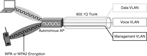
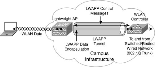
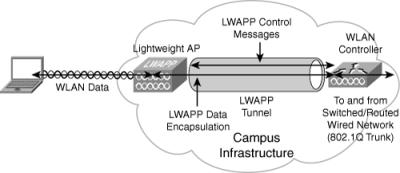


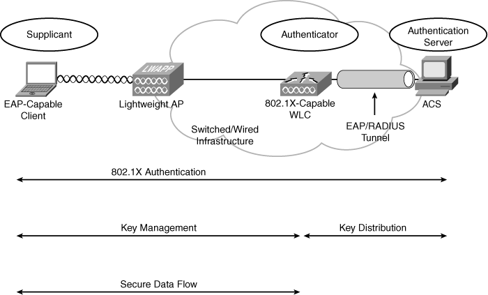

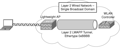
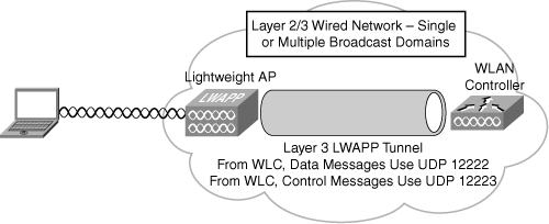
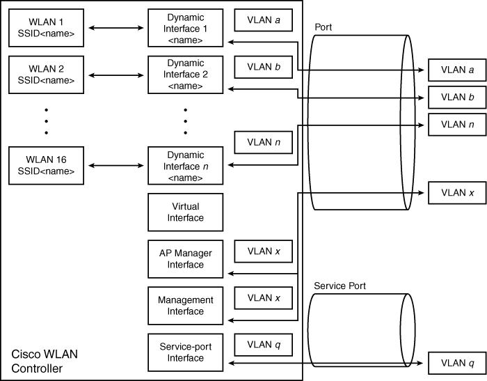
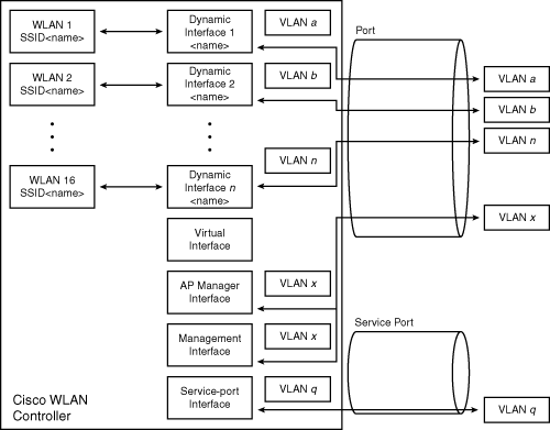
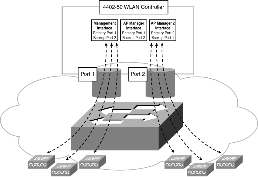
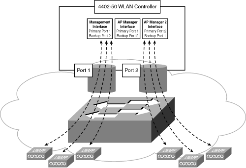
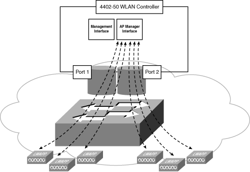
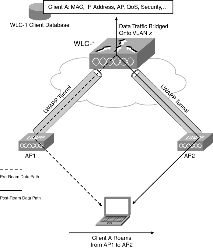
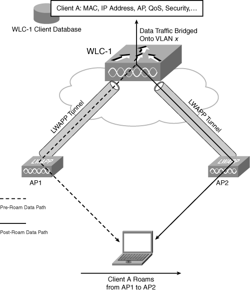
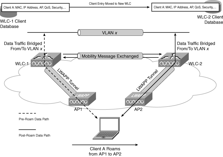
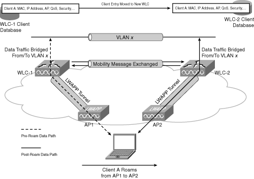
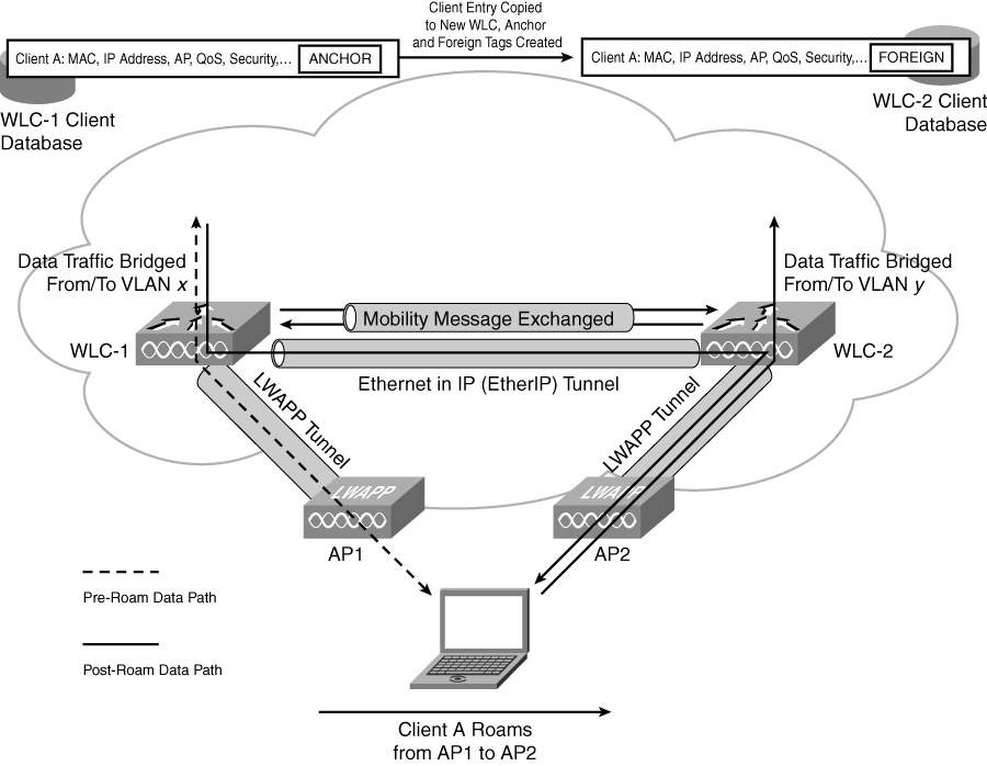
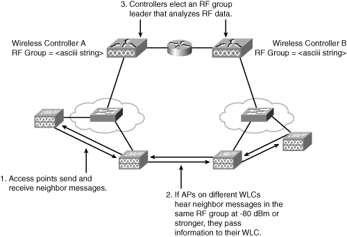
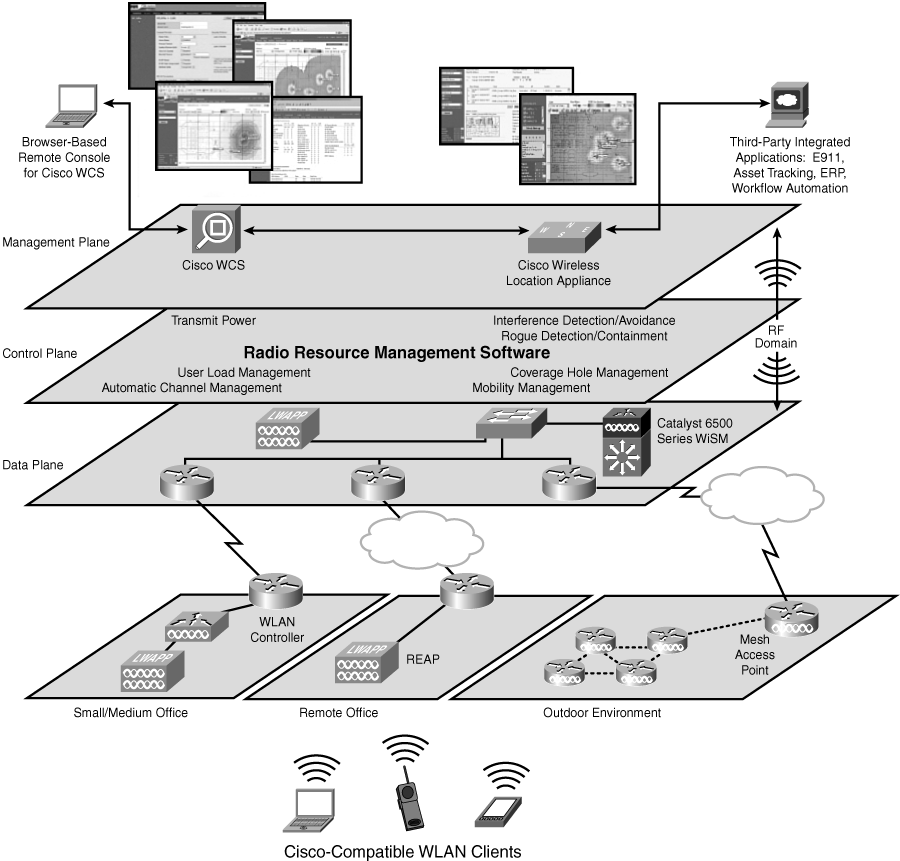
0 comments
Post a Comment