
Mitigating Layer 2 Attacks
![]() Like routers, both Layer 2 and Layer 3 switches have their own set of network security requirements. Access to switches is a convenient entry point for attackers who are intent on illegally gaining access to a corporate network. With access to a switch, an attacker can set up rogue access points and protocol analyzers, and launch all types of attacks from within the network. Attackers can even spoof the MAC and IP addresses of critical servers to do a great deal of damage.
Like routers, both Layer 2 and Layer 3 switches have their own set of network security requirements. Access to switches is a convenient entry point for attackers who are intent on illegally gaining access to a corporate network. With access to a switch, an attacker can set up rogue access points and protocol analyzers, and launch all types of attacks from within the network. Attackers can even spoof the MAC and IP addresses of critical servers to do a great deal of damage.
 Basic Switch Operation
![]() Unlike hubs, switches can regulate the flow of data between their ports by creating “instant” networks that contain only the two end devices communicating with each other at that moment in time. When end systems send data frames, their source and destination addresses are not changed throughout the switched domain. Switches maintain content-addressable memory (CAM) lookup tables to track the source MAC addresses located on the switch ports. These lookup tables are populated by an address-learning process on the switch. If the destination MAC address of a frame is not known, or if the frame received by the switch is destined for a broadcast or multicast MAC address, the switch forwards the frame to all ports. Because of their capability to isolate traffic and create instant networks, you can use switches to divide a physical network into multiple logical segments, or VLANs, using Layer 2 traffic segmenting.
Unlike hubs, switches can regulate the flow of data between their ports by creating “instant” networks that contain only the two end devices communicating with each other at that moment in time. When end systems send data frames, their source and destination addresses are not changed throughout the switched domain. Switches maintain content-addressable memory (CAM) lookup tables to track the source MAC addresses located on the switch ports. These lookup tables are populated by an address-learning process on the switch. If the destination MAC address of a frame is not known, or if the frame received by the switch is destined for a broadcast or multicast MAC address, the switch forwards the frame to all ports. Because of their capability to isolate traffic and create instant networks, you can use switches to divide a physical network into multiple logical segments, or VLANs, using Layer 2 traffic segmenting.
![]() Layer 2 is the data link layer in the OSI model and is one of seven layers designed to work together but with autonomy. Layer 2 operates above the physical layer, but below the network and transport layers, as shown in Figure 7-20.
Layer 2 is the data link layer in the OSI model and is one of seven layers designed to work together but with autonomy. Layer 2 operates above the physical layer, but below the network and transport layers, as shown in Figure 7-20.


![]() Layer 2 independence enables interoperability and interconnectivity. However, from a security perspective, Layer 2 independence creates a challenge because a compromise at one layer is not always known by the other layers. If the initial attack comes in at Layer 2, the rest of the network can be compromised in an instant. Network security is only as strong as the weakest link—and that link might be the data link layer.
Layer 2 independence enables interoperability and interconnectivity. However, from a security perspective, Layer 2 independence creates a challenge because a compromise at one layer is not always known by the other layers. If the initial attack comes in at Layer 2, the rest of the network can be compromised in an instant. Network security is only as strong as the weakest link—and that link might be the data link layer.
Mitigating VLAN Attacks
![]() A VLAN is a logical broadcast domain that can span multiple physical LAN segments, as shown in Figure 7-21. Within the switched internetwork, VLANs provide segmentation and organizational flexibility. You can design a VLAN structure that lets you group together stations that are segmented logically by functions, project teams, and applications without regard to the physical location of the users. You can assign each switch port to only one VLAN, thereby adding a layer of security. Ports in a VLAN share broadcasts; ports in different VLANs do not share broadcasts. Containing broadcasts within a VLAN improves the overall performance of the network.
A VLAN is a logical broadcast domain that can span multiple physical LAN segments, as shown in Figure 7-21. Within the switched internetwork, VLANs provide segmentation and organizational flexibility. You can design a VLAN structure that lets you group together stations that are segmented logically by functions, project teams, and applications without regard to the physical location of the users. You can assign each switch port to only one VLAN, thereby adding a layer of security. Ports in a VLAN share broadcasts; ports in different VLANs do not share broadcasts. Containing broadcasts within a VLAN improves the overall performance of the network.

![]() Within the switched internetwork, VLANs provide segmentation and organizational flexibility. Using VLAN technology, you can group switch ports and their connected users into logically defined communities, such as coworkers in the same department, a cross-functional product team, or diverse user groups sharing the same network application.
Within the switched internetwork, VLANs provide segmentation and organizational flexibility. Using VLAN technology, you can group switch ports and their connected users into logically defined communities, such as coworkers in the same department, a cross-functional product team, or diverse user groups sharing the same network application.
![]() A VLAN can exist on a single switch or span multiple switches. VLANs can include stations in a single building or multiple-building infrastructures. VLANs can also connect across WANs.
A VLAN can exist on a single switch or span multiple switches. VLANs can include stations in a single building or multiple-building infrastructures. VLANs can also connect across WANs.
VLAN Hopping
![]() The VLAN architecture simplifies network maintenance and improves performance. However, VLAN operation opens the door to abuse. VLAN hopping allows traffic from one VLAN to be seen by another VLAN without first crossing a router. Under certain circumstances, attackers can sniff data and extract passwords and other sensitive information at will. The attack works by taking advantage of an incorrectly configured trunk port. By default, trunk ports have access to all VLANs and pass traffic for multiple VLANs across the same physical link, generally between switches. The data moving across these links may be encapsulated with IEEE 802.1Q or ISL.
The VLAN architecture simplifies network maintenance and improves performance. However, VLAN operation opens the door to abuse. VLAN hopping allows traffic from one VLAN to be seen by another VLAN without first crossing a router. Under certain circumstances, attackers can sniff data and extract passwords and other sensitive information at will. The attack works by taking advantage of an incorrectly configured trunk port. By default, trunk ports have access to all VLANs and pass traffic for multiple VLANs across the same physical link, generally between switches. The data moving across these links may be encapsulated with IEEE 802.1Q or ISL.
VLAN Hopping by Rogue Trunk
![]() In a basic VLAN hopping attack, the attacker takes advantage of the default automatic trunking configuration on most switches. The network attacker configures a system to spoof itself as a switch. This spoofing requires that the network attacker be capable of emulating either ISL or 802.1Q signaling along with Dynamic Trunking Protocol (DTP) signaling, as shown in Figure 7-22. By tricking a switch into thinking it is another switch that needs to trunk, an attacker can gain access to all the VLANs allowed on the trunk port. To succeed, this attack requires a configuration on the port that supports trunking, such as auto. As a result, the attacker is a member of all the VLANS that are trunked on the switch and can “hop” (that is, send and receive traffic) on all of those VLANs.
In a basic VLAN hopping attack, the attacker takes advantage of the default automatic trunking configuration on most switches. The network attacker configures a system to spoof itself as a switch. This spoofing requires that the network attacker be capable of emulating either ISL or 802.1Q signaling along with Dynamic Trunking Protocol (DTP) signaling, as shown in Figure 7-22. By tricking a switch into thinking it is another switch that needs to trunk, an attacker can gain access to all the VLANs allowed on the trunk port. To succeed, this attack requires a configuration on the port that supports trunking, such as auto. As a result, the attacker is a member of all the VLANS that are trunked on the switch and can “hop” (that is, send and receive traffic) on all of those VLANs.

![]() A VLAN hopping attack can be launched in one of two ways:
A VLAN hopping attack can be launched in one of two ways:
- Spoofing DTP messages from the attacking host to cause the switch to enter trunking mode: From here, the attacker can send traffic tagged with the target VLAN, and the switch then delivers the packets to the destination.
- Introducing a rogue switch and turning trunking on: The attacker can then access all the VLANs on the victim switch from the rogue switch.
![]() The best way to prevent a basic VLAN hopping attack is to turn off trunking on all ports except the ones that specifically require trunking. On the required trunking ports, disable DTP (auto trunking) negotiations and manually enable trunking.
The best way to prevent a basic VLAN hopping attack is to turn off trunking on all ports except the ones that specifically require trunking. On the required trunking ports, disable DTP (auto trunking) negotiations and manually enable trunking.
VLAN Hopping by Double Tagging
![]() The double-tagging (or double-encapsulated) VLAN hopping attack takes advantage of the way that hardware on most switches operates. Most switches perform only one level of 802.1Q decapsulation and allow an attacker, in specific situations, to embed a hidden 802.1Q tag inside the frame. This tag allows the frame to go to a VLAN that the outer 802.1Q tag did not specify. An important characteristic of the double-encapsulated VLAN hopping attack is that it works even if trunk ports are set to off.
The double-tagging (or double-encapsulated) VLAN hopping attack takes advantage of the way that hardware on most switches operates. Most switches perform only one level of 802.1Q decapsulation and allow an attacker, in specific situations, to embed a hidden 802.1Q tag inside the frame. This tag allows the frame to go to a VLAN that the outer 802.1Q tag did not specify. An important characteristic of the double-encapsulated VLAN hopping attack is that it works even if trunk ports are set to off.
![]() A double-tagging VLAN hopping attack follows four steps, as shown in Figure 7-23:
A double-tagging VLAN hopping attack follows four steps, as shown in Figure 7-23:
|
|
|
|
|
|
|
|
|
|
|
|


![]() Note: This attack works only if the trunk has the same native VLAN as the attacker.
Note: This attack works only if the trunk has the same native VLAN as the attacker.
![]() It is important to note that this attack, as shown in Figure 7-23, is unidirectional and works only when the attacker and trunk port have the same native VLAN. Thwarting this type of attack is not as easy as stopping basic VLAN hopping attacks. The best approach is to ensure that the native VLAN of the trunk ports is different from the native VLAN of the user ports.
It is important to note that this attack, as shown in Figure 7-23, is unidirectional and works only when the attacker and trunk port have the same native VLAN. Thwarting this type of attack is not as easy as stopping basic VLAN hopping attacks. The best approach is to ensure that the native VLAN of the trunk ports is different from the native VLAN of the user ports.
![]() To prevent a VLAN hopping attack that uses double 802.1Q encapsulation, the switch must look further into the packet to determine whether more than one VLAN tag is attached to a given frame. Unfortunately, the ASICs that most switches use are only hardware optimized to look for one tag and then switch the frame. The issue of performance versus security requires administrators to balance their requirements carefully.
To prevent a VLAN hopping attack that uses double 802.1Q encapsulation, the switch must look further into the packet to determine whether more than one VLAN tag is attached to a given frame. Unfortunately, the ASICs that most switches use are only hardware optimized to look for one tag and then switch the frame. The issue of performance versus security requires administrators to balance their requirements carefully.
![]() Mitigating VLAN hopping attacks that use double 802.1Q encapsulation requires several modifications to the VLAN configuration. One of the more important elements is to use a dedicated native VLAN for all trunk ports. This attack is easy to stop if you follow the best practice that native VLANs for trunk ports should never be used anywhere else on the switch. Also, disable all unused switch ports and place them in an unused VLAN.
Mitigating VLAN hopping attacks that use double 802.1Q encapsulation requires several modifications to the VLAN configuration. One of the more important elements is to use a dedicated native VLAN for all trunk ports. This attack is easy to stop if you follow the best practice that native VLANs for trunk ports should never be used anywhere else on the switch. Also, disable all unused switch ports and place them in an unused VLAN.
![]() You have the following options to control trunking for ports:
You have the following options to control trunking for ports:
- For links that you do not intend to trunk across, use the switchport mode access interface configuration command to disable trunking.
- For links that you do intend to trunk across, take the following actions:Use the switchport mode trunk interface configuration command to cause the interface to become a trunk link and use the switchport nonegotiate interface configuration command to prevent the generation of DTP frames.Use the switchport trunk native vlan vlan_number interface configuration command to set the native VLAN on the trunk to an unused VLAN. The default native VLAN is VLAN 1.
Preventing Spanning Tree Protocol Manipulation
![]() Even though redundant designs, shown in Figure 7-24, can eliminate the possibility of a single point of failure causing a loss of function for the entire switched or bridged network, you must consider problems that redundant designs can cause.
Even though redundant designs, shown in Figure 7-24, can eliminate the possibility of a single point of failure causing a loss of function for the entire switched or bridged network, you must consider problems that redundant designs can cause.

![]() Some of the problems that can occur with redundant links and devices in switched or bridged networks are as follows:
Some of the problems that can occur with redundant links and devices in switched or bridged networks are as follows:
- Broadcast storms: Without some loop-avoidance process in operation, each switch or bridge floods broadcasts endlessly. This situation is commonly called a broadcast storm.
- Multiple frame transmission: Multiple copies of unicast frames may be delivered to destination stations. Many protocols expect to receive only a single copy of each transmission. Multiple copies of the same frame can cause unrecoverable errors.
- MAC database instability: Instability in the content of the MAC address table results from copies of the same frame being received on different ports of the switch. Data forwarding can be impaired when the switch consumes the resources that are coping with instability in the MAC address table.
![]() Layer 2 LAN protocols, such as Ethernet, lack a mechanism to recognize and eliminate endlessly looping frames. Some Layer 3 protocols implement a Time to Live (TTL) mechanism that limits the number of times a Layer 3 networking device can retransmit a packet. Lacking such a mechanism, Layer 2 devices continue to retransmit looping traffic indefinitely.
Layer 2 LAN protocols, such as Ethernet, lack a mechanism to recognize and eliminate endlessly looping frames. Some Layer 3 protocols implement a Time to Live (TTL) mechanism that limits the number of times a Layer 3 networking device can retransmit a packet. Lacking such a mechanism, Layer 2 devices continue to retransmit looping traffic indefinitely.
![]() A loop-avoidance mechanism is required to solve each of these problems.
A loop-avoidance mechanism is required to solve each of these problems.
![]() Spanning Tree Protocol (STP) provides loop resolution by managing the physical paths to given network segments. STP allows physical path redundancy while preventing the undesirable effects of active loops in the network. STP is an IEEE committee standard defined as 802.1D.
Spanning Tree Protocol (STP) provides loop resolution by managing the physical paths to given network segments. STP allows physical path redundancy while preventing the undesirable effects of active loops in the network. STP is an IEEE committee standard defined as 802.1D.
![]() STP behaves as follows:
STP behaves as follows:
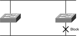
- STP forces certain ports into a standby state so that they do not listen to, forward, or flood data frames, as seen in Figure 7-25, where one switch has a port in blocking mode. The overall effect is that only one active path exists to the other network segment at any time.
- If there is a problem with connectivity to any of the segments within the network, STP reestablishes connectivity by automatically activating a previously inactive path, if one exists.
![]() STP performs three steps to provide a loop-free logical network topology:
STP performs three steps to provide a loop-free logical network topology:
|
|
|
|
|
|
|
|
|
![]() Figure 7-26 shows STP operations and the resulting topology.
Figure 7-26 shows STP operations and the resulting topology.
![]() Switches and bridges running the spanning-tree algorithm exchange configuration messages with other switches and bridges at regular intervals (every two seconds by default). Switches and bridges exchange these messages using a multicast frame called the bridge protocol data unit (BPDU). One of the pieces of information included in the BPDU is the bridge ID (BID).
Switches and bridges running the spanning-tree algorithm exchange configuration messages with other switches and bridges at regular intervals (every two seconds by default). Switches and bridges exchange these messages using a multicast frame called the bridge protocol data unit (BPDU). One of the pieces of information included in the BPDU is the bridge ID (BID).
![]() STP calls for each switch or bridge to be assigned a unique BID. Typically, the BID is composed of a priority value (2 bytes) and the bridge MAC address (6 bytes). The default priority, in accordance with IEEE 802.1D, is 32,768 (1000 0000 0000 0000 in binary, or 0x8000 in hex format), which is the midrange value. The root bridge is the bridge with the lowest BID.
STP calls for each switch or bridge to be assigned a unique BID. Typically, the BID is composed of a priority value (2 bytes) and the bridge MAC address (6 bytes). The default priority, in accordance with IEEE 802.1D, is 32,768 (1000 0000 0000 0000 in binary, or 0x8000 in hex format), which is the midrange value. The root bridge is the bridge with the lowest BID.
| Note |
|
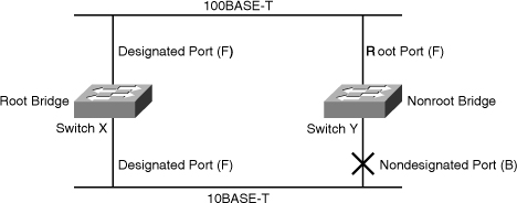
![]() In Figure 7-27, both switches are using the same default priority. The switch with the lowest MAC address is the root bridge. In Figure 7-26, switch X is the root bridge with the default priority of 0x8000 (hex,) or 32,768 in decimal, and a MAC address of 0c00.1111.1111.
In Figure 7-27, both switches are using the same default priority. The switch with the lowest MAC address is the root bridge. In Figure 7-26, switch X is the root bridge with the default priority of 0x8000 (hex,) or 32,768 in decimal, and a MAC address of 0c00.1111.1111.


![]() Figure 7-28 shows how a network attacker can use STP to change the topology of a network so that it appears that the network attacker host is a root bridge with a higher priority. The attacker sends out BPDUs with a better bridge ID, and as a result, becomes the root bridge. Now all the traffic for this switch domain passes through the new root bridge, which is actually the attacker system.
Figure 7-28 shows how a network attacker can use STP to change the topology of a network so that it appears that the network attacker host is a root bridge with a higher priority. The attacker sends out BPDUs with a better bridge ID, and as a result, becomes the root bridge. Now all the traffic for this switch domain passes through the new root bridge, which is actually the attacker system.

![]() By manipulating the STP root bridge parameters, network attackers hope to spoof their system, or a rogue switch that they add to the network, as the root bridge in the topology. To do this, the network attacker broadcasts out STP configuration and topology change BPDUs in an attempt to force spanning-tree recalculations. The BPDUs sent out by the system or switch of the network attacker announce that the attacking system has a lower bridge priority. If successful, the network attacker becomes the root bridge and sees a variety of frames that otherwise would not be seen.
By manipulating the STP root bridge parameters, network attackers hope to spoof their system, or a rogue switch that they add to the network, as the root bridge in the topology. To do this, the network attacker broadcasts out STP configuration and topology change BPDUs in an attempt to force spanning-tree recalculations. The BPDUs sent out by the system or switch of the network attacker announce that the attacking system has a lower bridge priority. If successful, the network attacker becomes the root bridge and sees a variety of frames that otherwise would not be seen.
| Note |
|
PortFast
![]() The spanning-tree PortFast feature causes an interface configured as a Layer 2 access port to transition from the blocking to the forwarding state immediately, bypassing the listening and learning states. You can use PortFast on Layer 2 access ports that connect to a single workstation or server, as shown on Figure 7-29, to allow those devices to connect to the network immediately, instead of waiting for spanning tree to converge.
The spanning-tree PortFast feature causes an interface configured as a Layer 2 access port to transition from the blocking to the forwarding state immediately, bypassing the listening and learning states. You can use PortFast on Layer 2 access ports that connect to a single workstation or server, as shown on Figure 7-29, to allow those devices to connect to the network immediately, instead of waiting for spanning tree to converge.

![]() If a port that is configured with PortFast receives a BPDU, spanning tree can put the port into the blocking state by using a feature called BPDU guard.
If a port that is configured with PortFast receives a BPDU, spanning tree can put the port into the blocking state by using a feature called BPDU guard.
| Caution |
|
![]() Table 7-6 lists the commands that you use to implement and verify PortFast on an interface.
Table 7-6 lists the commands that you use to implement and verify PortFast on an interface.
|
|
|
|---|---|
|
|
|
|
|
|
|
|
|
|
|
|
Mitigating STP Vulnerabilities
![]() To mitigate STP manipulation, use the BPDU guard and root guard enhancement commands available on Cisco switches to enforce the placement of the root bridge in the network and enforce the STP domain borders.
To mitigate STP manipulation, use the BPDU guard and root guard enhancement commands available on Cisco switches to enforce the placement of the root bridge in the network and enforce the STP domain borders.
BPDU Guard
![]() The STP BPDU guard feature is designed to enable network designers to keep the active network topology predictable. BPDU guard is used to protect the switched network from the problems that may be caused by the receipt of BPDUs on ports that should not be receiving them. The receipt of unexpected BPDUs might be accidental or might be part of an unauthorized attempt to add a switch to the network.
The STP BPDU guard feature is designed to enable network designers to keep the active network topology predictable. BPDU guard is used to protect the switched network from the problems that may be caused by the receipt of BPDUs on ports that should not be receiving them. The receipt of unexpected BPDUs might be accidental or might be part of an unauthorized attempt to add a switch to the network.
![]() BPDU guard is best deployed toward user-facing ports to prevent rogue switch network extensions by an attacker.
BPDU guard is best deployed toward user-facing ports to prevent rogue switch network extensions by an attacker.
![]() The global command to activate BPDU guard on all ports with PortFast enabled is as follows:
The global command to activate BPDU guard on all ports with PortFast enabled is as follows:
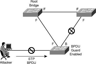
![]() In Figure 7-30, the attacker starts sending out spoofed BPDUs in an effort to become the root bridge. Upon receipt of a BPDU, the BPDU guard feature disables the port.
In Figure 7-30, the attacker starts sending out spoofed BPDUs in an effort to become the root bridge. Upon receipt of a BPDU, the BPDU guard feature disables the port.
Root Guard
![]() The root guard feature of Cisco switches is designed to provide a way to enforce the placement of root bridges in the network. Root guard limits the switch ports out of which the root bridge can be negotiated. If a root guard–enabled port receives BPDUs that are superior to those that the current root bridge is sending, that port is moved to a root-inconsistent state, which is effectively equal to an STP listening state, and no data traffic is forwarded across that port.
The root guard feature of Cisco switches is designed to provide a way to enforce the placement of root bridges in the network. Root guard limits the switch ports out of which the root bridge can be negotiated. If a root guard–enabled port receives BPDUs that are superior to those that the current root bridge is sending, that port is moved to a root-inconsistent state, which is effectively equal to an STP listening state, and no data traffic is forwarded across that port.
![]() Because an administrator can manually set the bridge priority of a switch to zero, root guard might seem unnecessary. However, setting the priority of a switch to zero does not guarantee that switch will be elected as the root bridge, because another switch could have a priority of zero and a lower MAC address, and therefore a lower BID.
Because an administrator can manually set the bridge priority of a switch to zero, root guard might seem unnecessary. However, setting the priority of a switch to zero does not guarantee that switch will be elected as the root bridge, because another switch could have a priority of zero and a lower MAC address, and therefore a lower BID.
![]() Root guard is best deployed toward ports that connect to switches that should not be the root bridge.
Root guard is best deployed toward ports that connect to switches that should not be the root bridge.
![]() The command to enable root guard on a per-interface basis is as follows:
The command to enable root guard on a per-interface basis is as follows:
![]() In Figure 7-31, the attacker starts sending out spoofed BPDUs in an effort to become the root bridge. Upon receipt of a BPDU, the switch with the root guard feature configured on that port ignores the BPDU and puts the port in a root-inconsistent state. The port will recover as soon as the offending BPDUs cease.
In Figure 7-31, the attacker starts sending out spoofed BPDUs in an effort to become the root bridge. Upon receipt of a BPDU, the switch with the root guard feature configured on that port ignores the BPDU and puts the port in a root-inconsistent state. The port will recover as soon as the offending BPDUs cease.


Confirming Spanning-Tree State
![]() To display information about the state of spanning tree, use the show spanning-tree summary command.
To display information about the state of spanning tree, use the show spanning-tree summary command.
![]() Example 7-1 shows that BPDU guard is enabled.
Example 7-1 shows that BPDU guard is enabled.
Root bridge for: Bridge group 1, VLAN0001, VLAN0004-VLAN1005
VLAN1013-VLAN1499, VLAN2001-VLAN4094
EtherChannel misconfiguration guard is enabled
Extended system ID is enabled
Portfast is enabled by default
PortFast BPDU Guard is enabled
Portfast BPDU Filter is disabled by default
Loopguard is disabled by default
UplinkFast is disabled
BackboneFast is disabled
Pathcost method used is long
CAM Table Overflow Attacks
![]() The CAM table in a switch contains the MAC addresses that can be reached off a given physical port of a switch and the associated VLAN parameters for each. When a Layer 2 switch receives a frame, the switch looks in the CAM table for the destination MAC address. If an entry exists for the MAC address in the CAM table, the switch forwards the frame to the MAC address port designated in the CAM table. If the MAC address does not exist in the CAM table, the switch acts like a hub and forwards the frame out every port on the switch.
The CAM table in a switch contains the MAC addresses that can be reached off a given physical port of a switch and the associated VLAN parameters for each. When a Layer 2 switch receives a frame, the switch looks in the CAM table for the destination MAC address. If an entry exists for the MAC address in the CAM table, the switch forwards the frame to the MAC address port designated in the CAM table. If the MAC address does not exist in the CAM table, the switch acts like a hub and forwards the frame out every port on the switch.
![]() The key to understanding how CAM-overflow attacks work is to know that CAM tables are limited in size. MAC flooding takes advantage of this limitation by bombarding the switch with fake source MAC addresses until the switch CAM table is full. If enough entries are entered into the CAM table before other entries are expired, the CAM table fills up to the point that no new entries can be accepted.
The key to understanding how CAM-overflow attacks work is to know that CAM tables are limited in size. MAC flooding takes advantage of this limitation by bombarding the switch with fake source MAC addresses until the switch CAM table is full. If enough entries are entered into the CAM table before other entries are expired, the CAM table fills up to the point that no new entries can be accepted.
![]() In a CAM table overflow attack, a network intruder floods the switch with a large number of invalid source MAC addresses until the CAM table fills up. When that occurs, the switch begins to flood all incoming traffic to all ports because there is no room in the CAM table to learn any legitimate MAC addresses. The switch, in essence, acts like a hub. As a result, the attacker can see all the frames sent from a victim host to another host without a CAM table entry. CAM table overflow floods traffic only within the local VLAN so that the intruder will see only traffic within the local VLAN to which the intruder is connected. If the intruder does not maintain the flood of invalid source MAC addresses, the switch eventually ages out older MAC address entries from the CAM table and begins to act like a switch again.
In a CAM table overflow attack, a network intruder floods the switch with a large number of invalid source MAC addresses until the CAM table fills up. When that occurs, the switch begins to flood all incoming traffic to all ports because there is no room in the CAM table to learn any legitimate MAC addresses. The switch, in essence, acts like a hub. As a result, the attacker can see all the frames sent from a victim host to another host without a CAM table entry. CAM table overflow floods traffic only within the local VLAN so that the intruder will see only traffic within the local VLAN to which the intruder is connected. If the intruder does not maintain the flood of invalid source MAC addresses, the switch eventually ages out older MAC address entries from the CAM table and begins to act like a switch again.
![]() In Figure 7-32, the macof program is running on Host C. This tool floods a switch with packets that contain randomly generated source and destination MAC and IP addresses. Over a short period, the CAM table in the switch fills up until it cannot accept new entries. When the CAM table fills up, the switch begins to flood all frames that it receives.
In Figure 7-32, the macof program is running on Host C. This tool floods a switch with packets that contain randomly generated source and destination MAC and IP addresses. Over a short period, the CAM table in the switch fills up until it cannot accept new entries. When the CAM table fills up, the switch begins to flood all frames that it receives.


![]() As long as macof is left running, the CAM table on the switch remains full. When this happens, the switch begins to flood all received frames out every port so that frames sent from any host are also flooded out of port 3/25 on the switch.
As long as macof is left running, the CAM table on the switch remains full. When this happens, the switch begins to flood all received frames out every port so that frames sent from any host are also flooded out of port 3/25 on the switch.
![]() The CAM table overflow attack can be mitigated by configuring port security on the switch. With port security, you can either statically specify the MAC addresses on a particular switch port or you can allow the switch to dynamically learn a fixed number of MAC addresses for a switch port. To statically specify the MAC addresses on switch ports is far too unmanageable a solution for a production environment; however, allowing the switch to dynamically learn a fixed number of MAC addresses for a port is a more administratively scalable solution.
The CAM table overflow attack can be mitigated by configuring port security on the switch. With port security, you can either statically specify the MAC addresses on a particular switch port or you can allow the switch to dynamically learn a fixed number of MAC addresses for a switch port. To statically specify the MAC addresses on switch ports is far too unmanageable a solution for a production environment; however, allowing the switch to dynamically learn a fixed number of MAC addresses for a port is a more administratively scalable solution.
MAC Address Spoofing Attacks
![]() MAC spoofing attacks involve the use of a known MAC address of another host to attempt to make the target switch forward frames destined for the remote host to the network attacker. By sending a single frame with the source Ethernet address of the other host, the network attacker overwrites the CAM table entry so that the switch forwards packets destined for the host to the network attacker instead. Until the host sends traffic, it does not receive any traffic. When the host sends out traffic, the CAM table entry is rewritten once more so that it moves back to the original port.
MAC spoofing attacks involve the use of a known MAC address of another host to attempt to make the target switch forward frames destined for the remote host to the network attacker. By sending a single frame with the source Ethernet address of the other host, the network attacker overwrites the CAM table entry so that the switch forwards packets destined for the host to the network attacker instead. Until the host sends traffic, it does not receive any traffic. When the host sends out traffic, the CAM table entry is rewritten once more so that it moves back to the original port.
![]() Figure 7-33 shows how MAC spoofing works. In the beginning, the switch has learned that Host A is on port 1, Host B is on port 2, and Host C is on port 3. Host B (attacker) sends out a packet identifying itself with the source MAC address of Host A. This traffic causes the switch to move the location of Host A in its CAM table from port 1 to port 2. Traffic from Host C destined to Host A is now visible to Host B and not to Host A.
Figure 7-33 shows how MAC spoofing works. In the beginning, the switch has learned that Host A is on port 1, Host B is on port 2, and Host C is on port 3. Host B (attacker) sends out a packet identifying itself with the source MAC address of Host A. This traffic causes the switch to move the location of Host A in its CAM table from port 1 to port 2. Traffic from Host C destined to Host A is now visible to Host B and not to Host A.


![]() This attack can also be mitigated using port security.
This attack can also be mitigated using port security.
Using Port Security
![]() You can use the port security feature to restrict input to an interface by limiting and identifying the MAC addresses of the stations that are allowed to access the port. When you assign secure MAC addresses to a secure port, the port does not forward packets with source addresses outside the group of defined addresses.
You can use the port security feature to restrict input to an interface by limiting and identifying the MAC addresses of the stations that are allowed to access the port. When you assign secure MAC addresses to a secure port, the port does not forward packets with source addresses outside the group of defined addresses.
![]() Port security allows you to statically specify MAC addresses for a port or permit the switch to dynamically learn a limited number of MAC addresses. By limiting the number of permitted MAC addresses on a port to one, you can use port security to control unauthorized expansion of the network.
Port security allows you to statically specify MAC addresses for a port or permit the switch to dynamically learn a limited number of MAC addresses. By limiting the number of permitted MAC addresses on a port to one, you can use port security to control unauthorized expansion of the network.
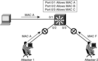
![]() When a secure port receives a packet, the source MAC address of the packet is compared to the list of secure source addresses that were manually configured or autoconfigured (learned) on the port. If a MAC address of a device attached to the port differs from the list of secure addresses, either the port shuts down until it is administratively enabled (default mode) or the port drops incoming packets from the unsecure host. The behavior of the port depends on how you configure it to respond to a security violation. In Figure 7-34, traffic from Attacker 1 and Attacker 2 will be dropped at the switch because the source MAC addresses of these frames do not match MAC addresses in the list of secured (allowed) addresses.
When a secure port receives a packet, the source MAC address of the packet is compared to the list of secure source addresses that were manually configured or autoconfigured (learned) on the port. If a MAC address of a device attached to the port differs from the list of secure addresses, either the port shuts down until it is administratively enabled (default mode) or the port drops incoming packets from the unsecure host. The behavior of the port depends on how you configure it to respond to a security violation. In Figure 7-34, traffic from Attacker 1 and Attacker 2 will be dropped at the switch because the source MAC addresses of these frames do not match MAC addresses in the list of secured (allowed) addresses.
![]() It is recommended that you configure the port security feature to shut down a port instead of just dropping packets from insecure hosts. If port security does not shut down a port, it is possible that there will be too much load from an attack, and the port will be disabled anyway.
It is recommended that you configure the port security feature to shut down a port instead of just dropping packets from insecure hosts. If port security does not shut down a port, it is possible that there will be too much load from an attack, and the port will be disabled anyway.
| Note |
|
| Tip |
|
![]() To configure port security on an access port, follow these steps (see Table 7-7 for command details):
To configure port security on an access port, follow these steps (see Table 7-7 for command details):
|
|
|
|---|---|
|
|
|
|
|
|
|
|
|
|
|
|
|
|
|
|
|
|
|
|
|
|
|
| |||
|
|
| |||
|
|
| |||
|
|
| |||
|
|
|
|
|
|
|---|---|
|
|
|
|
|
|
|
|
|
|
|
|
| Tip |
|
![]() Use the no switchport port-security interface configuration command to return the interface to the default condition of not being a secure port. The sticky secure addresses remain part of the running configuration. To remove the sticky secure addresses from the running configuration, use the no mac-address mac-address command.
Use the no switchport port-security interface configuration command to return the interface to the default condition of not being a secure port. The sticky secure addresses remain part of the running configuration. To remove the sticky secure addresses from the running configuration, use the no mac-address mac-address command.
![]() Use the no switchport port-security maximum value interface configuration command to return the interface to the default number of secure MAC addresses.
Use the no switchport port-security maximum value interface configuration command to return the interface to the default number of secure MAC addresses.
![]() Use the no switchport port-security violation {protect | restrict} interface configuration command to return the violation mode to the default condition (shutdown mode).
Use the no switchport port-security violation {protect | restrict} interface configuration command to return the violation mode to the default condition (shutdown mode).
![]() You can use port security aging to set the aging time for static and dynamic secure addresses on a port. Each port supports two types of aging:
You can use port security aging to set the aging time for static and dynamic secure addresses on a port. Each port supports two types of aging:
- Absolute: The secure addresses on the port are deleted after the specified aging time.
- Inactivity: The secure addresses on the port are deleted only if the secure addresses are inactive for the specified aging time.
![]() You can use this feature to remove and add secure MAC addresses on a secure port without manually deleting the existing secure MAC addresses and still limit the number of secure addresses on a port. Also, you can enable or disable the aging of statically configured secure addresses on a per-port basis.
You can use this feature to remove and add secure MAC addresses on a secure port without manually deleting the existing secure MAC addresses and still limit the number of secure addresses on a port. Also, you can enable or disable the aging of statically configured secure addresses on a per-port basis.
![]() Use the switchport port-security aging {static | time time | type {absolute | inactivity}} command to enable or disable static aging for the secure port, or set the aging time or type. Table 7-9 provides the details of the switchport port-security again parameters.
Use the switchport port-security aging {static | time time | type {absolute | inactivity}} command to enable or disable static aging for the secure port, or set the aging time or type. Table 7-9 provides the details of the switchport port-security again parameters.
|
|
|
|---|---|
|
|
|
|
|
|
|
|
|
|
|
|
![]() Example 7-2 shows a typical port security configuration for a voice port. Two MAC addresses are allowed, and they are to be learned dynamically. One MAC address is for the IP phone, and the other IP address is for the PC connected to the IP phone. Violations of this policy result in the port being shut down, and the aging timeout for the learned MAC addresses is set to two hours.
Example 7-2 shows a typical port security configuration for a voice port. Two MAC addresses are allowed, and they are to be learned dynamically. One MAC address is for the IP phone, and the other IP address is for the PC connected to the IP phone. Violations of this policy result in the port being shut down, and the aging timeout for the learned MAC addresses is set to two hours.
Switch(config-if)# switchport port-security
Switch(config-if)# switchport port-security maximum 2
Switch(config-if)# switchport port-security violation shutdown
Switch(config-if)# switchport port-security mac-address sticky
Switch(config-if)# switchport port-security aging time 120
![]() Use the show port-security command to view port security settings for the switch, including violation count, configured interfaces, and security violation actions.
Use the show port-security command to view port security settings for the switch, including violation count, configured interfaces, and security violation actions.
![]() Use the show port-security [interface interface-id] command to view port security settings for the specified interface, including the maximum allowed number of secure MAC addresses for each interface, the number of secure MAC addresses on the interface, the number of security violations that have occurred, and the violation mode.
Use the show port-security [interface interface-id] command to view port security settings for the specified interface, including the maximum allowed number of secure MAC addresses for each interface, the number of secure MAC addresses on the interface, the number of security violations that have occurred, and the violation mode.
![]() Example 7-3 shows that port security is enabled on port fa0/12 with a maximum MAC address count of 2. Currently, there are no MAC addresses learned on that port, and the violation action has been set to shut down the port.
Example 7-3 shows that port security is enabled on port fa0/12 with a maximum MAC address count of 2. Currently, there are no MAC addresses learned on that port, and the violation action has been set to shut down the port.
Secure Port MaxSecureAddr CurrentAddr SecurityViolation Security Action
(Count) (Count) (Count)
––––––––––––––––––––––––––––––––––––––––––––––––––––––––––––––––––––––––––-
Fa0/12 2 0 0 Shutdown
––––––––––––––––––––––––––––––––––––––––––––––––––––––––––––––––––––––––––-
Total Addresses in System (excluding one mac per port) : 0
Max Addresses limit in System (excluding one mac per port) : 1024
![]() Example 7-4 demonstrates output from the show port-security interface fa0/12 command, revealing that a violation has occurred, which means that more than one MAC address has been seen on the port. The port has been shutdown because of this policy violation, as confirmed by the secure-down port status.
Example 7-4 demonstrates output from the show port-security interface fa0/12 command, revealing that a violation has occurred, which means that more than one MAC address has been seen on the port. The port has been shutdown because of this policy violation, as confirmed by the secure-down port status.
Port Security : Enabled
Port status : Secure-down
Violation mode : Shutdown
Maximum MAC Addresses : 1
Total MAC Addresses : 2
Configured MAC Addresses : 0
Aging time : 120 mins
Aging type : Absolute
SecureStatic address aging : Disabled
Security Violation Count : 1
![]() Use the show port-security [interface interface-id] address command to view all the secure MAC addresses that are configured on all switch interfaces, or on a specified interface, with aging information for each address.
Use the show port-security [interface interface-id] address command to view all the secure MAC addresses that are configured on all switch interfaces, or on a specified interface, with aging information for each address.
![]() Example 7-5 shows that port fa0/12 is in VLAN 1 and has a secured MAC address of 0000.ffff.aaaa, which means that the host with the 0000.ffff.aaaa MAC address can connect to port fa0/12.
Example 7-5 shows that port fa0/12 is in VLAN 1 and has a secured MAC address of 0000.ffff.aaaa, which means that the host with the 0000.ffff.aaaa MAC address can connect to port fa0/12.
Secure Mac Address Table
––––––––––––––––––––––––––––––––––––––––––––––––––––––––––––––––––––––––––-
Vlan Mac Address Type Ports Remaining Age
(mins)
–––– ––––––––––- –––– ––––- ––––––––––––-
1 0000.ffff.aaaa SecureConfigured Fa0/12 -
––––––––––––––––––––––––––––––––––––––––––––––––––––––––––––––––––––––––––-
Total Addresses in System (excluding one mac per port) : 0
Max Addresses limit in System (excluding one mac per port) : 1024
![]() Network managers need a way to monitor who is using the network and where they are. In Figure 7-35, if port Fa2/1 is secure, an SNMP trap will be generated when MAC D disappears from the CAM table of the switch.
Network managers need a way to monitor who is using the network and where they are. In Figure 7-35, if port Fa2/1 is secure, an SNMP trap will be generated when MAC D disappears from the CAM table of the switch.

![]() The MAC address notification feature sends SNMP traps to the network management station (NMS) whenever a new MAC address is added to, or an old address is deleted from, the forwarding tables. MAC notifications are generated only for dynamic and secure MAC addresses.
The MAC address notification feature sends SNMP traps to the network management station (NMS) whenever a new MAC address is added to, or an old address is deleted from, the forwarding tables. MAC notifications are generated only for dynamic and secure MAC addresses.
![]() MAC address notification allows the network administrator to monitor MAC addresses that are learned and MAC addresses that age out and are removed from the switch.
MAC address notification allows the network administrator to monitor MAC addresses that are learned and MAC addresses that age out and are removed from the switch.
![]() Use the mac address-table notification change global configuration command to enable the MAC address notification feature on the switch.
Use the mac address-table notification change global configuration command to enable the MAC address notification feature on the switch.
Additional Switch Security Features
![]() The sections that follow describe the additional security features that are available with Cisco switches.
The sections that follow describe the additional security features that are available with Cisco switches.
Switched Port Analyzer
![]() You can analyze the network traffic that passes through ports or VLANs by using Switched Port Analyzer (SPAN) or Remote Switched Port Analyzer (RSPAN) to send a copy of the traffic to another port on the switch, or to a port on another switch, that has been connected to a network analyzer or other monitoring or security device. SPAN copies (or mirrors) traffic received or sent (or both) on source ports or source VLANs to a destination port for analysis. SPAN does not affect the switching of network traffic on the source ports or VLANs. You must dedicate the destination port for SPAN use. Except for traffic that is required for the SPAN or RSPAN session, destination ports do not receive or forward traffic.
You can analyze the network traffic that passes through ports or VLANs by using Switched Port Analyzer (SPAN) or Remote Switched Port Analyzer (RSPAN) to send a copy of the traffic to another port on the switch, or to a port on another switch, that has been connected to a network analyzer or other monitoring or security device. SPAN copies (or mirrors) traffic received or sent (or both) on source ports or source VLANs to a destination port for analysis. SPAN does not affect the switching of network traffic on the source ports or VLANs. You must dedicate the destination port for SPAN use. Except for traffic that is required for the SPAN or RSPAN session, destination ports do not receive or forward traffic.
![]() An intrusion detection system (IDS) has the capability to detect misuse, abuse, and unauthorized access to networked resources. You can use SPAN to mirror traffic to another port where a probe or an IDS sensor is connected, as shown in Figure 7-36. When an IDS sensor detects an intruder, the sensor can send out a TCP reset that tears down the intruder connection within the network, immediately removing the intruder from the network.
An intrusion detection system (IDS) has the capability to detect misuse, abuse, and unauthorized access to networked resources. You can use SPAN to mirror traffic to another port where a probe or an IDS sensor is connected, as shown in Figure 7-36. When an IDS sensor detects an intruder, the sensor can send out a TCP reset that tears down the intruder connection within the network, immediately removing the intruder from the network.


![]() Example 7-6 shows how to set up SPAN session 1 for monitoring source port traffic to a destination port. First, any existing SPAN configuration for session 1 is deleted, and then bidirectional traffic is mirrored from source port Gigabit Ethernet 0/1 to destination port Gigabit Ethernet 0/2, retaining the encapsulation method.
Example 7-6 shows how to set up SPAN session 1 for monitoring source port traffic to a destination port. First, any existing SPAN configuration for session 1 is deleted, and then bidirectional traffic is mirrored from source port Gigabit Ethernet 0/1 to destination port Gigabit Ethernet 0/2, retaining the encapsulation method.
Switch(config)# monitor session 1 source interface gigabitethernet0/1
Switch(config)# monitor session 1 destination interface gigabitethernet0/2 encapsulation replicate
Switch(config)# end
| Note |
|
Remote SPAN
![]() Figure 7-37 shows that an RSPAN VLAN has been created for the forwarding of traffic from switch to switch to reach the IDS, which analyzes the traffic for malicious behavior. Source ports for the spanned traffic are found on all three switches resulting in the IDS examining traffic that is forwarded by all of these devices. As the attacker traffic leaves the router, a copy of it will be forwarded to the IDS for examination.
Figure 7-37 shows that an RSPAN VLAN has been created for the forwarding of traffic from switch to switch to reach the IDS, which analyzes the traffic for malicious behavior. Source ports for the spanned traffic are found on all three switches resulting in the IDS examining traffic that is forwarded by all of these devices. As the attacker traffic leaves the router, a copy of it will be forwarded to the IDS for examination.


![]() To configure RSPAN, you start by configuring the RSPAN VLAN. Example 7-7 shows the command to create VLAN 901 and configure it as an RSPAN VLAN.
To configure RSPAN, you start by configuring the RSPAN VLAN. Example 7-7 shows the command to create VLAN 901 and configure it as an RSPAN VLAN.
Switch(config-vlan)# remote-span
![]() Next, it is necessary to configure the RSPAN source ports and VLANs. Example 7-8 shows a variety of sources.
Next, it is necessary to configure the RSPAN source ports and VLANs. Example 7-8 shows a variety of sources.
Switch3(config)# monitor session 2 source interface fastethernet 5/15 , 7/3 rx
Switch4(config)# monitor session 2 source interface gigabitethernet 1/2 tx
Switch5(config)# monitor session 2 source interface port-channel 102
Switch6(config)# monitor session 2 source filter vlan 2 - 3
Switch7(config)# monitor session 2 destination remote vlan 901
![]() Finally, you configure the RSPAN traffic to be forwarded out an interface toward where the IDS resides. Example 7-9 configures traffic that is destined for VLAN 901 to be forwarded out interface FastEthernet 1/2.
Finally, you configure the RSPAN traffic to be forwarded out an interface toward where the IDS resides. Example 7-9 configures traffic that is destined for VLAN 901 to be forwarded out interface FastEthernet 1/2.
Switch(config)# monitor session 2 destination interface fastethernet 1/2
![]() To display an RSPAN configuration, use the show monitor session command. Example 7-10 shows that the FastEthernet interfaces 1/1, 1/2, and 1/3 are configured as source ports to only receive traffic, and VLAN 901 is configured as the RSPAN VLAN.
To display an RSPAN configuration, use the show monitor session command. Example 7-10 shows that the FastEthernet interfaces 1/1, 1/2, and 1/3 are configured as source ports to only receive traffic, and VLAN 901 is configured as the RSPAN VLAN.
Session 2
————————————
Type : Remote Source Session
Source Ports:
RX Only: Fa1/1-3
TX Only: None
Both: None
Source VLANs:
RX Only: None
TX Only: None
Both: None
Source RSPAN VLAN: None
Destination Ports: None
Filter VLANs: None
Dest RSPAN VLAN: 901
LAN Storm Suppression
![]() A LAN storm occurs when packets flood the LAN, creating excessive traffic and degrading network performance, as shown in Figure 7-38. Errors in the protocol-stack implementation, mistakes in network configurations, or users issuing a DoS attack can cause a storm. Broadcast storms can also occur on networks that have protocols that rely heavily on broadcasts (for example, some of the protocols in AppleTalk and Novell networking).
A LAN storm occurs when packets flood the LAN, creating excessive traffic and degrading network performance, as shown in Figure 7-38. Errors in the protocol-stack implementation, mistakes in network configurations, or users issuing a DoS attack can cause a storm. Broadcast storms can also occur on networks that have protocols that rely heavily on broadcasts (for example, some of the protocols in AppleTalk and Novell networking).

![]() By limiting the number of incoming broadcast, multicast, and unicast frames on each port, the processing and forwarding of frames is limited. Storm control (or traffic suppression) limits the number of incoming frames by monitoring packets that pass from an interface to the switching bus and determines whether the packet is unicast, multicast, or broadcast. The switch counts the number of packets of a specified type received within the one-second time interval and compares the measurement with a predefined suppression-level threshold. Storm control blocks traffic on a port when the rising threshold is reached.
By limiting the number of incoming broadcast, multicast, and unicast frames on each port, the processing and forwarding of frames is limited. Storm control (or traffic suppression) limits the number of incoming frames by monitoring packets that pass from an interface to the switching bus and determines whether the packet is unicast, multicast, or broadcast. The switch counts the number of packets of a specified type received within the one-second time interval and compares the measurement with a predefined suppression-level threshold. Storm control blocks traffic on a port when the rising threshold is reached.
![]() For example, on a Catalyst 3550 switch when a multicast storm occurs, the networking device blocks all traffic (broadcast, multicast, and unicast traffic) except for control traffic, such as BPDU frames. By default, when a broadcast or unicast storm occurs, the networking device blocks only the broadcast or unicast traffic. This blocking includes traffic that might be necessary in the network, such as routing protocol traffic. Therefore, you must assess the required thresholds on each port against their potential for attack and assess the required traffic for normal network operation. Also, the network should be designed and configured to remove or limit the normal broadcast and multicast traffic.
For example, on a Catalyst 3550 switch when a multicast storm occurs, the networking device blocks all traffic (broadcast, multicast, and unicast traffic) except for control traffic, such as BPDU frames. By default, when a broadcast or unicast storm occurs, the networking device blocks only the broadcast or unicast traffic. This blocking includes traffic that might be necessary in the network, such as routing protocol traffic. Therefore, you must assess the required thresholds on each port against their potential for attack and assess the required traffic for normal network operation. Also, the network should be designed and configured to remove or limit the normal broadcast and multicast traffic.
![]() Use the storm-control interface configuration command to enable storm control on an interface and set the threshold value for each type of traffic. You can enter the storm-control suppression level as a percentage of total bandwidth of the port, as a rate in packets per second at which traffic is received, or as a rate in bits per second at which traffic is received.
Use the storm-control interface configuration command to enable storm control on an interface and set the threshold value for each type of traffic. You can enter the storm-control suppression level as a percentage of total bandwidth of the port, as a rate in packets per second at which traffic is received, or as a rate in bits per second at which traffic is received.
![]() When you specify the traffic suppression level as a percentage (up to two decimal places) of the total bandwidth, the level can be from 0.00 to 100.00. A threshold value of 100 percent means that no limit is placed on that type of traffic. A value of 0.0 means that all traffic of that type on that port is blocked.
When you specify the traffic suppression level as a percentage (up to two decimal places) of the total bandwidth, the level can be from 0.00 to 100.00. A threshold value of 100 percent means that no limit is placed on that type of traffic. A value of 0.0 means that all traffic of that type on that port is blocked.
![]() Threshold percentages are approximations because of hardware limitations and the way in which packets of different sizes are counted. Depending on the packet sizes that make up the incoming traffic, the actual enforced threshold might differ from the configured level by several percentage points.
Threshold percentages are approximations because of hardware limitations and the way in which packets of different sizes are counted. Depending on the packet sizes that make up the incoming traffic, the actual enforced threshold might differ from the configured level by several percentage points.
| Note |
|
![]() The full command syntax for the storm-control command is as follows:
The full command syntax for the storm-control command is as follows:
storm-control {{broadcast | multicast | unicast} level {level [level-low] | bps
bps [bps-low] | pps pps [pps-low]}} | {action {shutdown | trap}}
![]() Table 7-10 shows the details of the storm-control command.
Table 7-10 shows the details of the storm-control command.
|
|
|
|---|---|
|
|
|
|
|
|
|
|
|
|
| |
|
|
|
|
|
|
|
|
|
![]() If you configure the action to be taken as shutdown, the port is error disabled during a storm, and you must use the no shutdown interface configuration command to bring the interface out of this state.
If you configure the action to be taken as shutdown, the port is error disabled during a storm, and you must use the no shutdown interface configuration command to bring the interface out of this state.
![]() When a storm occurs and the action is to filter traffic, if the falling suppression level is not specified, the switch blocks all traffic until the traffic rate drops below the rising suppression level. If the falling suppression level is specified, the switch blocks traffic until the traffic rate drops below this level.
When a storm occurs and the action is to filter traffic, if the falling suppression level is not specified, the switch blocks all traffic until the traffic rate drops below the rising suppression level. If the falling suppression level is specified, the switch blocks traffic until the traffic rate drops below this level.
![]() Use the following command to verify the storm control settings:
Use the following command to verify the storm control settings:
show storm-control [interface][{broadcast | multicast | unicast | history}]
Layer 2 Best Practices
![]() The following list suggests Layer 2 security best practices. All of these suggestions are dependent on your security policy:
The following list suggests Layer 2 security best practices. All of these suggestions are dependent on your security policy:
- Manage switches in as secure a manner as possible (SSH, OOB, permit lists, and so on).
- Always use a dedicated VLAN ID for trunk ports.
- Do not use VLAN 1 for anything.
- Set all user ports to nontrunking (unless you are using Cisco VoIP).
- Use port security where possible for access ports.
- Selectively use SNMP and treat community strings like root passwords.
- Enable STP attack mitigation (BPDU guard, root guard).
- Use Cisco Discovery Protocol only where necessary (with phones it is useful).
- Disable all unused ports and put them in an unused VLAN.
![]() It is important to manage switches like routers, using secure protocols or out-of-band methods if policy permits it. Because VLAN 1 is a known management VLAN, it is recommended that you avoid using it. Turn off services that are not necessary and ports that are not being used. Implement the various security services that have been covered in this chapter as necessary and as supported by your hardware. Turn Cisco Discovery Protocol (CDP) off on ports that do not connect to network devices, with the exception of ports that connect to Cisco IP phones.
It is important to manage switches like routers, using secure protocols or out-of-band methods if policy permits it. Because VLAN 1 is a known management VLAN, it is recommended that you avoid using it. Turn off services that are not necessary and ports that are not being used. Implement the various security services that have been covered in this chapter as necessary and as supported by your hardware. Turn Cisco Discovery Protocol (CDP) off on ports that do not connect to network devices, with the exception of ports that connect to Cisco IP phones.
Summary
![]() Layer 2 security is often an overlooked aspect of network security. It is important for security practitioners to remember that all software is vulnerable to poor programming. Buffer overflows can be the worst of these problems. The goals of endpoint security include protection from viruses, worms, and Trojan horses. SAN and voice security are also increasingly important because these technologies are growing in popularity in the modern enterprise.
Layer 2 security is often an overlooked aspect of network security. It is important for security practitioners to remember that all software is vulnerable to poor programming. Buffer overflows can be the worst of these problems. The goals of endpoint security include protection from viruses, worms, and Trojan horses. SAN and voice security are also increasingly important because these technologies are growing in popularity in the modern enterprise.
![]() The major points covered in this chapter are as follows:
The major points covered in this chapter are as follows:
- An endpoint is an individual computer system or device that acts as a network client.
- Cisco offers different security appliances such as IronPort Systems, Cisco NAC Appliance, Cisco ASA, and Cisco MARS.
- A SAN is a specialized network that enables fast, reliable access among servers and external storage resources.
- VoIP is the transmission of voice traffic over IP-based networks. Hackers can tamper with voice systems, user identities, and telephone configurations and intercept voice-mail messages.
- Assigning voice traffic to specific VLANs to logically segment voice and data traffic is an industrywide accepted best practice.
- Always use a dedicated VLAN ID for trunk ports and do not use VLAN 1 for anything. Also, set all user ports to nontrunking (unless you are using Cisco VoIP).
- Use port security where possible for access ports and enable STP attack mitigation (BPDU guard, root guard).
- VLAN hopping and MAC spoofing attacks are possible on switched networks and measures should be put in place to protect against those attacks.
References
![]() For additional information, refer to these resources:
For additional information, refer to these resources:
- Cisco Systems, Inc. Cisco Catalyst 6500 Series Switches: Private VLAN Catalyst Switch Support Matrix, http://tinyurl.com/2w22d6
- Cisco Systems, Inc. Securing Networks with Private VLANs and VLAN Access Control Lists, http://www.cisco.com/warp/public/473/90.shtml
- Cisco Systems, Inc. LAN Security: Introduction, http://tinyurl.com/594lpb
- Cisco Systems, Inc. Identity Based Networking Services Solution, http://www.cisco.com/en/US/netsol/ns340/ns394/ns171/ns75/networking_solutions_sub_sub_solution_home.html
- Cisco Systems, Inc. Catalyst 6500 Release 12.2SXH Software Configuration Guide: Configuring Private VLANs (PVLANs), http://www.cisco.com/en/US/docs/switches/lan/catalyst6500/ios/12.2SX/configuration/guide/pvlans.html
- Cisco Systems, Inc. Catalyst 4500 Series Switch Cisco IOS Software Configuration Guide, 12.1(13)EW: Configuring Private VLANs, http://tinyurl.com/5mhtdl.
- IronPort Systems. http://www.ironport.com
- Cisco Systems, Inc. Cisco Security Agent Introduction, http://www.cisco.com/go/csa
- Cisco Systems, Inc. Network Admission Control Introduction, http://www.cisco.com/go/nac
- Cisco Systems, Inc. Storage Networking Introduction, http://www.cisco.com/go/storagenetworking
- Cisco Systems, Inc. Data Center Networking, http://www.cisco.com/go/datacenter
- Storage Network Industry Association. http://www.snia.org
- ANSI T11 FC Projects. http://www.t11.org/index.htm
- Vacca, J. R. The Essential Guide to Storage Area Networks (Prentice Hall, 2001)
- Wallace, K. Cisco Voice over IP (CVOICE) Self-Study (Cisco Press, 2007)
0 comments
Post a Comment