
Understanding First Hop Redundancy Protocols
![]() Hosts and servers in a subnet need a gateway to reach devices that are not in the same subnet. Because gateways perform a key role in operations of all devices, their availability is paramount. Providing redundant gateways is one solution but to ensure that they operate in a way that provides redundancy and load balancing, they need be configured for first hop redundancy protocol such as HSRP, VRRP, and GLBP. This section covers the alternatives to gateway protocols and then explains each of the first hop redundancy protocols in detail.
Hosts and servers in a subnet need a gateway to reach devices that are not in the same subnet. Because gateways perform a key role in operations of all devices, their availability is paramount. Providing redundant gateways is one solution but to ensure that they operate in a way that provides redundancy and load balancing, they need be configured for first hop redundancy protocol such as HSRP, VRRP, and GLBP. This section covers the alternatives to gateway protocols and then explains each of the first hop redundancy protocols in detail.
 Introduction to First Hop Redundancy Protocol
![]() First hop redundancy protocols such as HSRP and VRRP provide default gateway redundancy with one router acting as the active gateway router with one or more other routers held in standby mode. GLBP enables all available gateway routers to load share and be active at the same time. But before first hop redundancy protocols were available, networks relied on Proxy ARP and static gateway configuration.
First hop redundancy protocols such as HSRP and VRRP provide default gateway redundancy with one router acting as the active gateway router with one or more other routers held in standby mode. GLBP enables all available gateway routers to load share and be active at the same time. But before first hop redundancy protocols were available, networks relied on Proxy ARP and static gateway configuration.
Proxy ARP
![]() Before default gateway was supported on most IP clients, networks were relying on the proxy ARP feature to reach IP devices outside the IP client subnet. Cisco IOS Software ran proxy ARP to enable hosts that had no knowledge of routing options to obtain the MAC address of a gateway that can forward packets off the local subnet.
Before default gateway was supported on most IP clients, networks were relying on the proxy ARP feature to reach IP devices outside the IP client subnet. Cisco IOS Software ran proxy ARP to enable hosts that had no knowledge of routing options to obtain the MAC address of a gateway that can forward packets off the local subnet.
![]() In Figure 5-27, if the proxy ARP router receives an ARP request for an IP address that it knows is not on the same interface as the request sender, it generates an ARP reply packet giving its own local MAC address as the destination MAC address of the IP address being resolved. The host that sent the ARP request sends all packets destined for the resolved IP address to the MAC address of the router. The router then forwards the packets toward the intended host. Proxy ARP is enabled by default.
In Figure 5-27, if the proxy ARP router receives an ARP request for an IP address that it knows is not on the same interface as the request sender, it generates an ARP reply packet giving its own local MAC address as the destination MAC address of the IP address being resolved. The host that sent the ARP request sends all packets destined for the resolved IP address to the MAC address of the router. The router then forwards the packets toward the intended host. Proxy ARP is enabled by default.


![]() With proxy ARP, the end-user station behaves as if the destination device were connected to its own network segment. If the responsible router fails, the source end station continues to send packets for that IP destination to the MAC address of the failed router, and the packets are discarded.
With proxy ARP, the end-user station behaves as if the destination device were connected to its own network segment. If the responsible router fails, the source end station continues to send packets for that IP destination to the MAC address of the failed router, and the packets are discarded.
![]() Eventually, the proxy ARP MAC address will age out of the workstation’s ARP cache. The workstation might eventually acquire the address of another proxy ARP failover router, but the workstation cannot send packets off the local segment during this failover time.
Eventually, the proxy ARP MAC address will age out of the workstation’s ARP cache. The workstation might eventually acquire the address of another proxy ARP failover router, but the workstation cannot send packets off the local segment during this failover time.
![]() For further information on proxy ARP, refer to RFC 1027, “Using ARP to Implement Transparent Subnet Gateways.”
For further information on proxy ARP, refer to RFC 1027, “Using ARP to Implement Transparent Subnet Gateways.”
Static Default Gateway
![]() Now that a default gateway is configured on most devices, the Proxy ARP feature is not used anymore. Nevertheless, each client receives only one default gateway; there is no means by which to configure a secondary gateway, even if a second route exists to carry packets off the local segment.
Now that a default gateway is configured on most devices, the Proxy ARP feature is not used anymore. Nevertheless, each client receives only one default gateway; there is no means by which to configure a secondary gateway, even if a second route exists to carry packets off the local segment.
![]() For example, primary and secondary paths between the building access submodule and the building distribution submodule provide continuous access if a link failure occurs at the building access layer. Primary and secondary paths between the building distribution layer and the building core layer provide continuous operations should a link fail at the building distribution layer.
For example, primary and secondary paths between the building access submodule and the building distribution submodule provide continuous access if a link failure occurs at the building access layer. Primary and secondary paths between the building distribution layer and the building core layer provide continuous operations should a link fail at the building distribution layer.
![]() In Figure 5-28, Router A is responsible for routing packets to server (10.9.1.50). If Router A becomes unavailable, routing protocols can quickly and dynamically converge and determine that Router B will now transfer packets that would otherwise have gone through Router A. Most workstations, servers, and printers, however, do not receive this dynamic routing information.
In Figure 5-28, Router A is responsible for routing packets to server (10.9.1.50). If Router A becomes unavailable, routing protocols can quickly and dynamically converge and determine that Router B will now transfer packets that would otherwise have gone through Router A. Most workstations, servers, and printers, however, do not receive this dynamic routing information.
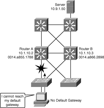
![]() End devices are typically configured with a single default gateway IP address that does not change when network topology changes occur. If the router whose IP address is configured as the default gateway fails, the local device cannot send packets off the local network segment, effectively disconnecting it from the rest of the network. Even if a redundant router exists that could serve as a default gateway for that segment, there is no dynamic method by which these devices can determine the address of a new default gateway.
End devices are typically configured with a single default gateway IP address that does not change when network topology changes occur. If the router whose IP address is configured as the default gateway fails, the local device cannot send packets off the local network segment, effectively disconnecting it from the rest of the network. Even if a redundant router exists that could serve as a default gateway for that segment, there is no dynamic method by which these devices can determine the address of a new default gateway.
Hot Standby Router Protocol (HSRP)
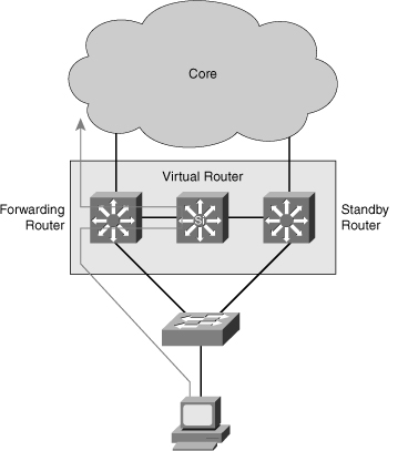
![]() HSRP is a redundancy protocol developed by Cisco to provide gateway redundancy without any additional configuration on the end devices in the subnet. With HSRP configured between a set of routers, they work in concert to present the appearance of a single virtual router to the hosts on the LAN, as shown in Figure 5-29. By sharing an IP address and a MAC (Layer 2) address, two or more routers can act as a single virtual router.
HSRP is a redundancy protocol developed by Cisco to provide gateway redundancy without any additional configuration on the end devices in the subnet. With HSRP configured between a set of routers, they work in concert to present the appearance of a single virtual router to the hosts on the LAN, as shown in Figure 5-29. By sharing an IP address and a MAC (Layer 2) address, two or more routers can act as a single virtual router.
![]() The IP address of the virtual router will be configured as the default gateway for the workstations on a specific IP segment. When frames are to be sent from the workstation to the default gateway, the workstation uses ARP to resolve the MAC address associated with the IP address of the default gateway. The ARP resolution returns the MAC address of the virtual router. Frames sent to the MAC address of the virtual router can then be physically processed by the active router that is part of that virtual router group. The physical router that forwards this traffic is transparent to the end stations.
The IP address of the virtual router will be configured as the default gateway for the workstations on a specific IP segment. When frames are to be sent from the workstation to the default gateway, the workstation uses ARP to resolve the MAC address associated with the IP address of the default gateway. The ARP resolution returns the MAC address of the virtual router. Frames sent to the MAC address of the virtual router can then be physically processed by the active router that is part of that virtual router group. The physical router that forwards this traffic is transparent to the end stations.
![]() HSRP provides the mechanism for determining which router should take the active role in forwarding traffic. HSRP also has a mechanism to determine when that active role must be taken over by a standby router. The transition from one forwarding router to another is transparent to the end devices.
HSRP provides the mechanism for determining which router should take the active role in forwarding traffic. HSRP also has a mechanism to determine when that active role must be taken over by a standby router. The transition from one forwarding router to another is transparent to the end devices.
![]() For example, when the active router or the links between the routers fail, the standby router stops seeing hello messages from the active router. The standby router then assumes the role of the forwarding router, as shown in Figure 5-30. Because the new forwarding router assumes both the IP and MAC address of the virtual router, the end stations see no disruption in service.
For example, when the active router or the links between the routers fail, the standby router stops seeing hello messages from the active router. The standby router then assumes the role of the forwarding router, as shown in Figure 5-30. Because the new forwarding router assumes both the IP and MAC address of the virtual router, the end stations see no disruption in service.


![]() HSRP active and standby routers send hello messages to multicast address 224.0.0.2 User Datagram Protocol (UDP) port 1985. Hello messages are used to communicate between routers in the HSRP group. All the routers in the HSRP group need to be L2 adjacent so that hello packets can be exchanged.
HSRP active and standby routers send hello messages to multicast address 224.0.0.2 User Datagram Protocol (UDP) port 1985. Hello messages are used to communicate between routers in the HSRP group. All the routers in the HSRP group need to be L2 adjacent so that hello packets can be exchanged.
![]() All the routers in an HSRP group have specific roles and interact in specific manners:
All the routers in an HSRP group have specific roles and interact in specific manners:
- Virtual router: An IP and MAC address pair that end devices have configured as their default gateway. The active router processes all packets and frames sent to the virtual router address. The virtual router processes no physical frames. There is one virtual router in an HSRP group.
- Active router: Within an HSRP group, one router is elected to be the active router. The active router physically forwards packets sent to the MAC address of the virtual router. There is one active router in an HSRP group.
![]() The active router responds to traffic for the virtual router. If an end station sends a packet to the virtual router MAC address, the active router receives and processes that packet. If an end station sends an ARP request with the virtual router IP address, the active router replies with the virtual router MAC address.
The active router responds to traffic for the virtual router. If an end station sends a packet to the virtual router MAC address, the active router receives and processes that packet. If an end station sends an ARP request with the virtual router IP address, the active router replies with the virtual router MAC address.
![]() In Figure 5-31, Router A assumes the active role and forwards all frames addressed to the assigned HSRP MAC address of 0000.0c07.acxx, where xx is the HSRP group identifier.
In Figure 5-31, Router A assumes the active role and forwards all frames addressed to the assigned HSRP MAC address of 0000.0c07.acxx, where xx is the HSRP group identifier.


- Standby Router: Listens for periodic hello messages. When the active router fails, the other HSRP routers stop seeing hello messages from the active router. The standby router then assumes the role of the active router. There is one standby router in a HSRP group.
- Other Routers: There can be more than two routers in a HSRP group but only one active and one standby router is possible. The other routers remain in the initial state and if both the active and standby routers fail, all routers in the group contend for the active and standby router roles.
HSRP States
![]() A router in an HSRP group can be in one of these states: initial, listen, speak, standby, or active. When a router exists in one of these states, it performs the actions required for that state. Not all HSRP routers in the group will transition through all states. For example, if there were three routers in the HSRP group, the router that is not the standby or active router will remain in the listen state.
A router in an HSRP group can be in one of these states: initial, listen, speak, standby, or active. When a router exists in one of these states, it performs the actions required for that state. Not all HSRP routers in the group will transition through all states. For example, if there were three routers in the HSRP group, the router that is not the standby or active router will remain in the listen state.
![]() Table 5-3 describes the different HSRP states.
Table 5-3 describes the different HSRP states.
|
|
|
|---|---|
|
|
|
|
|
|
|
|
|
|
|
|
|
|
|
HSRP State Transition
![]() All routers begin in the initial state, which is the starting state and indicates that HSRP is not running. This state is entered via a configuration change, such as when HSRP is enabled on an interface, or when an HSRP-enabled interface is first brought up, such as when the no shutdown command is issued.
All routers begin in the initial state, which is the starting state and indicates that HSRP is not running. This state is entered via a configuration change, such as when HSRP is enabled on an interface, or when an HSRP-enabled interface is first brought up, such as when the no shutdown command is issued.
![]() The purpose of the listen state is to determine if there are already active or standby routers for the group. In the speak state, the routers are actively participating in the election of the active router or standby router or both. HSRP uses the hello and hold time to determine when it moves to different states. The timers are explained later in this chapter.
The purpose of the listen state is to determine if there are already active or standby routers for the group. In the speak state, the routers are actively participating in the election of the active router or standby router or both. HSRP uses the hello and hold time to determine when it moves to different states. The timers are explained later in this chapter.
![]() In Figure 5-32, Router A starts. As it is the first router for standby Group 1 in the subnet, it transits through the listen and speak states and then becomes the active router. Router B starts after A. While router B is in listen state, Router A is already assuming the standby and then the active role. As there is already an existing active router, B assumes the standby role.
In Figure 5-32, Router A starts. As it is the first router for standby Group 1 in the subnet, it transits through the listen and speak states and then becomes the active router. Router B starts after A. While router B is in listen state, Router A is already assuming the standby and then the active role. As there is already an existing active router, B assumes the standby role.


![]() When two routers participate in an election process, a priority can be configured to determine which router should be active. Without specific priority configuration, each router has a default priority of 100, and the router with the highest IP address is elected as the active router.
When two routers participate in an election process, a priority can be configured to determine which router should be active. Without specific priority configuration, each router has a default priority of 100, and the router with the highest IP address is elected as the active router.
![]() Regardless of other routers priorities or IP addresses, an active router will stay active by default. A new election occurs only if the active router is removed. When the standby router is removed, a new election is made to replace the standby. This default behavior can be changed with the option preempt, examined in later section of this chapter.
Regardless of other routers priorities or IP addresses, an active router will stay active by default. A new election occurs only if the active router is removed. When the standby router is removed, a new election is made to replace the standby. This default behavior can be changed with the option preempt, examined in later section of this chapter.
HSRP Active Router and Spanning Tree Topology
![]() In a redundant spanning-tree topology, some links are blocked. The spanning-tree topology has no awareness about the HSRP configuration. There is no automatic relationship between the HSRP active router election process and the Spanning Tree Root Bridge election process.
In a redundant spanning-tree topology, some links are blocked. The spanning-tree topology has no awareness about the HSRP configuration. There is no automatic relationship between the HSRP active router election process and the Spanning Tree Root Bridge election process.
![]() When configuring both spanning tree and HSRP (or any other first hop redundancy protocol), you should make sure that the active router is the same as the root bridge for the corresponding VLAN. When the root bridge is different from the HSRP active router, a suboptimal path could result, as shown in Figure 5-33.
When configuring both spanning tree and HSRP (or any other first hop redundancy protocol), you should make sure that the active router is the same as the root bridge for the corresponding VLAN. When the root bridge is different from the HSRP active router, a suboptimal path could result, as shown in Figure 5-33.


Configuring HSRP
![]() Table 5-4 shows the commands needed to enable or disable HSRP on an interface.
Table 5-4 shows the commands needed to enable or disable HSRP on an interface.
|
|
|
|---|---|
|
|
|
|
|
|
![]() While running HSRP, the end-user stations must not discover the actual MAC addresses of the routers in the standby group. Any protocol that informs a host of a router’s actual address must be disabled. To ensure that the actual addresses of the participating HSRP routers are not discovered, enabling HSRP on a Cisco router interface automatically disables Internet Control Message Protocol (ICMP) redirects on that interface.
While running HSRP, the end-user stations must not discover the actual MAC addresses of the routers in the standby group. Any protocol that informs a host of a router’s actual address must be disabled. To ensure that the actual addresses of the participating HSRP routers are not discovered, enabling HSRP on a Cisco router interface automatically disables Internet Control Message Protocol (ICMP) redirects on that interface.
![]() After the standby ip command is issued, the interface changes to the appropriate state. When the router successfully executes the command, the router issues an HSRP message.
After the standby ip command is issued, the interface changes to the appropriate state. When the router successfully executes the command, the router issues an HSRP message.
HSRP Priority and Preempt
![]() Each standby group has its own active and standby routers. The network administrator can assign a priority value to each router in a standby group, allowing the administrator to control the order in which active routers for that group are selected.
Each standby group has its own active and standby routers. The network administrator can assign a priority value to each router in a standby group, allowing the administrator to control the order in which active routers for that group are selected.
![]() To set the priority value of a router, enter this command in interface configuration mode:
To set the priority value of a router, enter this command in interface configuration mode:
![]() Priority value can be from 0 to 255. The default value is 100.
Priority value can be from 0 to 255. The default value is 100.
![]() During the election process, the router with the highest priority in an HSRP group becomes the active router. If a tie occurs, the router with the highest configured IP address becomes active.
During the election process, the router with the highest priority in an HSRP group becomes the active router. If a tie occurs, the router with the highest configured IP address becomes active.
![]() To reinstate the default standby priority value, enter the no standby priority command.
To reinstate the default standby priority value, enter the no standby priority command.
![]() If the routers do not have preempt configured, a router that boots up significantly faster than the others in the standby group becomes the active router, regardless of the configured priority. The former active router can be configured to resume the forwarding router role by preempting a router with a lower priority. To enable a router to resume the forwarding router role, enter this command in interface configuration mode:
If the routers do not have preempt configured, a router that boots up significantly faster than the others in the standby group becomes the active router, regardless of the configured priority. The former active router can be configured to resume the forwarding router role by preempting a router with a lower priority. To enable a router to resume the forwarding router role, enter this command in interface configuration mode:
Switch(config-if)#standby [group-number] preempt {delay} [minimum delay] ![]() Figure 5-34 shows two Routers A and B configured with priorities of 110 and 90 respectively and Example 5-13 shows the configuration on Router A with preempt additional configured.
Figure 5-34 shows two Routers A and B configured with priorities of 110 and 90 respectively and Example 5-13 shows the configuration on Router A with preempt additional configured.
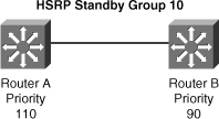
RouterA(config-if)# ip address 10.1.1.2 255.255.255.0
RouterA(config-if)# standby 10 ip 10.1.1.1
RouterA(config-if)# standby 10 priority 110
RouterA(config-if)# standby 10 preempt
![]() To remove the interface from preemptive status, enter the no standby group preempt command.
To remove the interface from preemptive status, enter the no standby group preempt command.
HSRP Authentication
![]() HSRP authentication prevents rogue routers on the network from joining the HSRP group.
HSRP authentication prevents rogue routers on the network from joining the HSRP group.
![]() HSRP authentication is enabled by configuration of an authentication string on all member devices of the HSRP group. The authentication string is a maximum of eight characters and the default keyword is cisco.
HSRP authentication is enabled by configuration of an authentication string on all member devices of the HSRP group. The authentication string is a maximum of eight characters and the default keyword is cisco.
![]() Example 5-14 shows the configuration of HSRP authentication with string value of xyz123.
Example 5-14 shows the configuration of HSRP authentication with string value of xyz123.
RouterA(config-if)# ip address 10.1.1.2 255.255.255.0
RouterA(config-if)# standby 10 ip 10.1.1.1
RouterA(config-if)# standby 10 priority 110
RouterA(config-if)# standby 10 preempt
RouterA(config-if)# standby 10 authentication xyz123
HSRP Timer Considerations and Configuration
![]() When an HSRP active router fails, the standby router detects the failure and assumes the active role. This mechanism relies on hello messages and holdtime intervals. The hello timer determines how often routers in the same Standby group exchange messages.
When an HSRP active router fails, the standby router detects the failure and assumes the active role. This mechanism relies on hello messages and holdtime intervals. The hello timer determines how often routers in the same Standby group exchange messages.
![]() The holdtime timer determines the time before the active or standby router is declared to be down.
The holdtime timer determines the time before the active or standby router is declared to be down.
![]() Ideally, to achieve fast convergence, these timers should be configured to be as low as possible. Within milliseconds after the active router fails, the standby router can detect the failure, expire the holdtime interval, and assume the active role.
Ideally, to achieve fast convergence, these timers should be configured to be as low as possible. Within milliseconds after the active router fails, the standby router can detect the failure, expire the holdtime interval, and assume the active role.
![]() Nevertheless, timers configuration should also take into account other parameters relevant to the network convergence. For example, both HSRP routers might be running a dynamic routing protocol. The routing protocol probably has no awareness of the HSRP configuration and sees both routers as individual hops toward other subnets. If HSRP failover occurs before the dynamic routing protocol converges, suboptimal routing information might still exist. In a worst-case scenario, the dynamic routing protocol continues seeing the failed router as the best next hop to other networks, and packets are lost, as shown in Figure 5-35. When configuring HSRP timers, make sure that they harmoniously match the other timers that can influence which path is chosen to carry packets in your network.
Nevertheless, timers configuration should also take into account other parameters relevant to the network convergence. For example, both HSRP routers might be running a dynamic routing protocol. The routing protocol probably has no awareness of the HSRP configuration and sees both routers as individual hops toward other subnets. If HSRP failover occurs before the dynamic routing protocol converges, suboptimal routing information might still exist. In a worst-case scenario, the dynamic routing protocol continues seeing the failed router as the best next hop to other networks, and packets are lost, as shown in Figure 5-35. When configuring HSRP timers, make sure that they harmoniously match the other timers that can influence which path is chosen to carry packets in your network.


![]() The hello message contains the priority of the router and hellotime and holdtime parameter values. The standby timer includes an msec parameter to allow for subsecond failovers. Lowering the hello timer results in increased traffic for hello messages and should be used cautiously.
The hello message contains the priority of the router and hellotime and holdtime parameter values. The standby timer includes an msec parameter to allow for subsecond failovers. Lowering the hello timer results in increased traffic for hello messages and should be used cautiously.
![]() If an active router sends a hello message, receiving routers consider that hello message to be valid for one holdtime. The holdtime value should be at least three times the value of the hellotime. The holdtime value must be greater than the value of the hellotime.
If an active router sends a hello message, receiving routers consider that hello message to be valid for one holdtime. The holdtime value should be at least three times the value of the hellotime. The holdtime value must be greater than the value of the hellotime.
![]() HSRP timers can be adjusted to tune the performance of HSRP on distribution devices, thereby increasing their resilience and reliability in routing packets off the local VLAN.
HSRP timers can be adjusted to tune the performance of HSRP on distribution devices, thereby increasing their resilience and reliability in routing packets off the local VLAN.
![]() By default, HSRP hellotime is 3 seconds and holdtime is 10 seconds, which means that failover time could be as much as 10 seconds for clients to start communicating with the new default gateway. In some cases, this interval might be excessive for application support. The hellotime and the holdtime parameters are both configurable. To configure the time between hello messages and the time before other group routers declare the active or standby router to be nonfunctioning, enter this command in interface configuration mode:
By default, HSRP hellotime is 3 seconds and holdtime is 10 seconds, which means that failover time could be as much as 10 seconds for clients to start communicating with the new default gateway. In some cases, this interval might be excessive for application support. The hellotime and the holdtime parameters are both configurable. To configure the time between hello messages and the time before other group routers declare the active or standby router to be nonfunctioning, enter this command in interface configuration mode:
- Switch(config-if)#standby group-number timers [msec] hellotime holdtime
![]() Hello and dead timer intervals must be identical for all devices within the HSRP group.
Hello and dead timer intervals must be identical for all devices within the HSRP group.
![]() Table 5-5 describes the options for standby message timer configuration.
Table 5-5 describes the options for standby message timer configuration.
|
|
|
|---|---|
|
|
|
|
|
|
|
|
|
|
|
|
![]() To reinstate the default standby-timer values, enter the no standby group timers command.
To reinstate the default standby-timer values, enter the no standby group timers command.
![]() The HSRP hellotime and holdtime can be set to millisecond values so that HSRP failover occurs in less than 1 second.
The HSRP hellotime and holdtime can be set to millisecond values so that HSRP failover occurs in less than 1 second.
![]() Preempt is an important feature of HSRP that enables the primary router to resume the active role when it comes back online after a failure or maintenance event. Preemption is a desired behavior because it forces a predictable routing path for the VLAN during normal operations and ensures that the Layer 3 forwarding path for a VLAN parallels the Layer 2 STP forwarding path whenever possible.
Preempt is an important feature of HSRP that enables the primary router to resume the active role when it comes back online after a failure or maintenance event. Preemption is a desired behavior because it forces a predictable routing path for the VLAN during normal operations and ensures that the Layer 3 forwarding path for a VLAN parallels the Layer 2 STP forwarding path whenever possible.
![]() When a preempting device is rebooted, HSRP preempt communication should not begin until the distribution switch has established full connectivity to the rest of the network. This enables the routing protocol convergence to occur more quickly, after the preferred router is in an active state.
When a preempting device is rebooted, HSRP preempt communication should not begin until the distribution switch has established full connectivity to the rest of the network. This enables the routing protocol convergence to occur more quickly, after the preferred router is in an active state.
![]() To accomplish this, measure the system boot time and set the HSRP preempt delay to a value of 50 percent greater than the boot time. This ensures that the primary distribution switch establishes full connectivity to the network before HSRP communication occurs.
To accomplish this, measure the system boot time and set the HSRP preempt delay to a value of 50 percent greater than the boot time. This ensures that the primary distribution switch establishes full connectivity to the network before HSRP communication occurs.
![]() For example, if the boot time for the distribution device is 150 seconds, the preempt delay should be set to 225 seconds.
For example, if the boot time for the distribution device is 150 seconds, the preempt delay should be set to 225 seconds.
![]() Example 5-15 shows the configuration of timers and the preempt delay configuration commands.
Example 5-15 shows the configuration of timers and the preempt delay configuration commands.
switch(config-if)# ip address 10.1.1.2 255.255.255.0
switch(config-if)# standby 10 ip 10.1.1.1
switch(config-if)# standby 10 priority 110
switch(config-if)# standby 10 preempt
switch(config-if)# standby 10 timers msec 200 msec 750
switch(config-if)# standby 10 preempt delay minimum 225
HSRP Versions
![]() HSRP version 1 is the default in IOS and it enables group numbers up to 255. Because one can have up to 4095 VLANs, one has to reuse the same HSRP group number on multiple interface if needed. This is allowed even though it might cause some confusion to the administrator. HSRPv1 uses the Virtual MAC address of the form 0000.0C07.ACXX (XX = HSRP group), and the HSRPv1 hello packets are sent to multicast address 224.0.0.2.
HSRP version 1 is the default in IOS and it enables group numbers up to 255. Because one can have up to 4095 VLANs, one has to reuse the same HSRP group number on multiple interface if needed. This is allowed even though it might cause some confusion to the administrator. HSRPv1 uses the Virtual MAC address of the form 0000.0C07.ACXX (XX = HSRP group), and the HSRPv1 hello packets are sent to multicast address 224.0.0.2.
![]() HSRP version 2 has been added to IOS (since 12.2 46SE or later) and it enables group numbers up to 4095. This enables you to use the VLAN number as the group number.
HSRP version 2 has been added to IOS (since 12.2 46SE or later) and it enables group numbers up to 4095. This enables you to use the VLAN number as the group number.
![]() With HSRP v2, the MAC address of the virtual router and the multicast address for the hello messages has been changed. The virtual MAC address is 0000.0C9F.FXXX (XXX=HSRP group), and hello packets are sent to multicast address 224.0.0.102.
With HSRP v2, the MAC address of the virtual router and the multicast address for the hello messages has been changed. The virtual MAC address is 0000.0C9F.FXXX (XXX=HSRP group), and hello packets are sent to multicast address 224.0.0.102.
![]() Also, the HSRPv2 has a different packet format than HSRPv1. Ensure that the same version is configured on all routers in a HSRP group. Otherwise hello messages are not understood. Version 1 is the default. Use the following command to change the version:
Also, the HSRPv2 has a different packet format than HSRPv1. Ensure that the same version is configured on all routers in a HSRP group. Otherwise hello messages are not understood. Version 1 is the default. Use the following command to change the version:
HSRP Interface Tracking
![]() Interface tracking enables the priority of a standby group router to be automatically adjusted, based on the availability of the router interfaces. When a tracked interface becomes unavailable, the HSRP priority of the router is decreased. When properly configured, the HSRP tracking feature ensures that a router with an unavailable key interface will relinquish the active router role.
Interface tracking enables the priority of a standby group router to be automatically adjusted, based on the availability of the router interfaces. When a tracked interface becomes unavailable, the HSRP priority of the router is decreased. When properly configured, the HSRP tracking feature ensures that a router with an unavailable key interface will relinquish the active router role.
![]() In Figure 5-36, the distribution switches monitor the uplink to the core switches. The uplink between the active forwarding device for the standby group and the core experiences a failure. Without HSRP enabled, the active device would detect the failed link and send an Internet Control Message Protocol (ICMP) redirect to the other device. However, when HSRP is enabled, ICMP redirects are disabled. The left switch now has the better path to the server.
In Figure 5-36, the distribution switches monitor the uplink to the core switches. The uplink between the active forwarding device for the standby group and the core experiences a failure. Without HSRP enabled, the active device would detect the failed link and send an Internet Control Message Protocol (ICMP) redirect to the other device. However, when HSRP is enabled, ICMP redirects are disabled. The left switch now has the better path to the server.


![]() The HSRP group tracks the uplink interfaces. If the uplink to the core on the right switch fails, the router automatically decrements the priority on that interface and sends hello messages with the decremented priority. The switch on the left now has a higher priority and with preempt enabled becomes the active router.
The HSRP group tracks the uplink interfaces. If the uplink to the core on the right switch fails, the router automatically decrements the priority on that interface and sends hello messages with the decremented priority. The switch on the left now has a higher priority and with preempt enabled becomes the active router.
![]() To configure HSRP with interface tracking, follow these steps:
To configure HSRP with interface tracking, follow these steps:
|
|
|
|
|
|
|
|
|
|
|
|
![]() Table 5-6 describes the variables in the HSRP tracking configuration command:
Table 5-6 describes the variables in the HSRP tracking configuration command:
[interface-priority]
|
|
|
|---|---|
|
|
|
|
|
|
|
|
|
|
|
|
![]() A router can track several interfaces. In Figure 5-36, SW4 tracks both fa0/23 and fa0/24. The configuration policy shown in Example 5-16 states that SW4 initial priority should be 110. SW3 initial priority should be left to its default value, 100. If SW4 loses its link fa0/24 to SW1, SW4 priority should become the same as SW3 priority. If a new election needs to occur, both multilayer switches have the same chances of becoming the active router. This decrement is made because fa0/24 is not the active link but just a backup. If fa0/23 (the active uplink) is lost, SW4 priority becomes lower than SW3 priority. If both fa0/23 and fa0/24 are lost, both decrements are applied and SW4 priority becomes 80.
A router can track several interfaces. In Figure 5-36, SW4 tracks both fa0/23 and fa0/24. The configuration policy shown in Example 5-16 states that SW4 initial priority should be 110. SW3 initial priority should be left to its default value, 100. If SW4 loses its link fa0/24 to SW1, SW4 priority should become the same as SW3 priority. If a new election needs to occur, both multilayer switches have the same chances of becoming the active router. This decrement is made because fa0/24 is not the active link but just a backup. If fa0/23 (the active uplink) is lost, SW4 priority becomes lower than SW3 priority. If both fa0/23 and fa0/24 are lost, both decrements are applied and SW4 priority becomes 80.
switch(config-if)# ip address 10.1.1.2 255.255.255.0
switch(config-if)# standby 10 ip 10.1.1.1
switch(config-if)# standby 10 priority 110
switch(config-if)# standby 10 preempt
switch(config-if)# standby 10 track fastethernet0/23 20
switch(config-if)# standby 10 track fastethernet0/24
![]() To disable interface tracking, enter the no standby group track command.
To disable interface tracking, enter the no standby group track command.
![]() The command to configure HSRP tracking on a multilayer switch is the same as on the external router, except that the interface type can be identified as a switch virtual interface (vlan followed by the vlan number assigned to that interface) or by a physical interface.
The command to configure HSRP tracking on a multilayer switch is the same as on the external router, except that the interface type can be identified as a switch virtual interface (vlan followed by the vlan number assigned to that interface) or by a physical interface.
![]() The internal routing device uses the same command as the external routing device to disable interface tracking.
The internal routing device uses the same command as the external routing device to disable interface tracking.
![]() Multiple tracking statements might be applied to an interface. For example, this might be useful if the currently active HSRP interface relinquishes its status only upon the failure of two (or more) tracked interfaces.
Multiple tracking statements might be applied to an interface. For example, this might be useful if the currently active HSRP interface relinquishes its status only upon the failure of two (or more) tracked interfaces.
HSRP Object Tracking
![]() The HSRP tracking feature can be used to track an object. When the conditions defined by this object are fulfilled, the router priority remains the same. As soon as the verification defined by the object fails, the router priority is decremented.
The HSRP tracking feature can be used to track an object. When the conditions defined by this object are fulfilled, the router priority remains the same. As soon as the verification defined by the object fails, the router priority is decremented.
![]() Tracked objects are defined in global configuration with the track keyword, as shown in Example 5-17, followed by an object number. You can track up to 500 objects.
Tracked objects are defined in global configuration with the track keyword, as shown in Example 5-17, followed by an object number. You can track up to 500 objects.
interface Select an interface to track
ip IP protocol
list Group objects in a list
rtr Response Time Reporter (RTR) entry
![]() Tracked objects offer a vast group of possibilities. You can track the following:
Tracked objects offer a vast group of possibilities. You can track the following:
- An interface: Just like the standby track interface command, a tracking object can verify the interface status (line-protocol). You can also track ip routing on the interface. This option tracks whether IP routing is enabled, whether an IP address is configured on the interface, and whether the interface state is up before reporting to the tracking client that the interface is up.
- IP route: A tracked IP-route object is considered up and reachable when a routing-table entry exists for the route and the route is not inaccessible. To provide a common interface to tracking clients, route metric values are normalized to the range of 0 to 255, where 0 is connected and 255 is inaccessible. You can track route reachability, or even metric values to determine best paths values to the target network. The tracking process uses a per-protocol configurable resolution value to convert the real metric to the scaled metric. The metric value communicated to clients is always such that a lower metric value is better than a higher metric value.
- A list of objects: Several objects can be tracked and their result compared to determine if one or several of them should trigger the “success” of “fail” condition.
- IP SLA: This special case enables you to track advanced parameters, such as IP reachability, delay, or jitter.
HSRP and IP SLA Tracking
![]() IP SLA tracking extends the HSRP interface tracking to enable it to track paths through the network.
IP SLA tracking extends the HSRP interface tracking to enable it to track paths through the network.
![]() In Figure 5-37, a Cisco IOS IP SLA measurement is being run between two switches across a network cloud.
In Figure 5-37, a Cisco IOS IP SLA measurement is being run between two switches across a network cloud.


![]() If the link fails, the priority of the active switch in the HSRP group is reduced, and the other switch connection via the upper network becomes the active router to reach the server.
If the link fails, the priority of the active switch in the HSRP group is reduced, and the other switch connection via the upper network becomes the active router to reach the server.
![]() Figure 5-37 also shows the configuration of IP SLA with HSRP, and it includes the following steps:
Figure 5-37 also shows the configuration of IP SLA with HSRP, and it includes the following steps:
|
|
|
|
|
|
|
|
|
|
|
|
Multiple HSRP Groups
![]() HSRP allows for only one active router in the same subnet. In a typical network, administrators would want to use all available routers to load share the traffic going across the network. Multigroup HSRP enables routers to simultaneously provide redundant backup and perform load sharing across different IP subnets.
HSRP allows for only one active router in the same subnet. In a typical network, administrators would want to use all available routers to load share the traffic going across the network. Multigroup HSRP enables routers to simultaneously provide redundant backup and perform load sharing across different IP subnets.
![]() In Figure 5-38, two HSRP-enabled routers participate in two separate VLANs, using 802.1Q. Running HSRP over trunking enables users to configure redundancy among multiple routers that are configured as front ends for VLAN IP subnets.
In Figure 5-38, two HSRP-enabled routers participate in two separate VLANs, using 802.1Q. Running HSRP over trunking enables users to configure redundancy among multiple routers that are configured as front ends for VLAN IP subnets.

![]() By configuring HSRP over trunks, users can eliminate situations in which a single point of failure causes traffic interruptions. This feature inherently provides some improvement in overall networking resilience by providing load balancing and redundancy capabilities between subnets and VLANs.
By configuring HSRP over trunks, users can eliminate situations in which a single point of failure causes traffic interruptions. This feature inherently provides some improvement in overall networking resilience by providing load balancing and redundancy capabilities between subnets and VLANs.
![]() For a VLAN, configure the same device to be both the spanning-tree root and the HSRP active router. This approach ensures that the Layer 2 forwarding path leads directly to the Layer 3 active router and so achieves maximum efficiency of load balancing on the routers and the trunks.
For a VLAN, configure the same device to be both the spanning-tree root and the HSRP active router. This approach ensures that the Layer 2 forwarding path leads directly to the Layer 3 active router and so achieves maximum efficiency of load balancing on the routers and the trunks.
![]() For each VLAN, a standby group, an IP addresses, and a single well-known MAC address with a unique group identifier is allocated to the group. Although up to 255 standby groups can be configured (4095 with version 2), it is advised that the actual number of group identifiers used be kept to a minimum. When you are configuring two distribution layer switches, typically you will require only two standby group identifiers, regardless of how many standby groups are created.
For each VLAN, a standby group, an IP addresses, and a single well-known MAC address with a unique group identifier is allocated to the group. Although up to 255 standby groups can be configured (4095 with version 2), it is advised that the actual number of group identifiers used be kept to a minimum. When you are configuring two distribution layer switches, typically you will require only two standby group identifiers, regardless of how many standby groups are created.
![]() Figure 5-39 shows the configuration for two HSRP groups for two VLANs and the corresponding STP root configuration.
Figure 5-39 shows the configuration for two HSRP groups for two VLANs and the corresponding STP root configuration.


![]() The left switch is root and active HSRP router for VLAN 10.
The left switch is root and active HSRP router for VLAN 10.
![]() The corresponding configuration of the right switch has the switch as root and active HSRP router for VLAN 20.
The corresponding configuration of the right switch has the switch as root and active HSRP router for VLAN 20.
HSRP Monitoring
![]() Use the show standby family of commands to verify HSRP state. Several arguments can be used. Show standby brief simply displays a summary of the HSRP configurations, as shown in Example 5-18. For each standby group, you can verify the local router neighbors.
Use the show standby family of commands to verify HSRP state. Several arguments can be used. Show standby brief simply displays a summary of the HSRP configurations, as shown in Example 5-18. For each standby group, you can verify the local router neighbors.
P indicates configured to preempt.
|
Interface Grp Pri P State Active Standby Virtual IP
Vl10 10 120 P Active local 10.1.10.3 10.1.10.1
Vl20 20 90 P Standby 10.1.20.3 local 10.1.20.1
switch# show standby neighbor vlan10
HSRP neighbors on Vlan10
10.1.10.3
Active groups: 10
No standby groups
![]() When simply typing show standby, a complete display is provided, as shown in Example 5-19.
When simply typing show standby, a complete display is provided, as shown in Example 5-19.
Vlan10 - Group 10
State is Active
Virtual IP address is 10.1.10.1
Active virtual MAC address is 0000.0c07.ac0a
Local virtual MAC address is 0000.0c07.ac0a (v1 default)
Hello time 3 sec, hold time 10 sec
Next hello sent in 1.248 secs
Preemption enabled
Active router is local
Standby router is 10.1.10.3, priority 90 (expires in 10.096 sec)
Priority 120 (configured 120)
Track interface Port-channel31 state Up decrement 30
Track interface Port-channel32 state Up decrement 30
Group name is "hsrp-Vl10-10" (default)
Vlan20 - Group 20
State is Standby
Virtual IP address is 10.1.20.1 Active virtual MAC address is 0000.0c07.ac14
Local virtual MAC address is 0000.0c07.ac14 (v1 default)
Hello time 3 sec, hold time 10 sec
Next hello sent in 2.064 secs
Preemption enabled
Active router is 10.1.10.3, priority 120 (expires in 10.032 sec)
Standby router is local
Priority 90 (configured 90)
Group name is "hsrp-Vl20-20" (default)
![]() The IP address and corresponding MAC address of the virtual router are maintained in the ARP table of each router in an HSRP group. As shown in Figure 5-40, the command show ip arp displays the ARP cache on a multilayer switch.
The IP address and corresponding MAC address of the virtual router are maintained in the ARP table of each router in an HSRP group. As shown in Figure 5-40, the command show ip arp displays the ARP cache on a multilayer switch.


![]() HSRP offers more detailed monitoring capabilities through the IOS debugging facility. Table 5-7 describes commands used to debug HSRP.
HSRP offers more detailed monitoring capabilities through the IOS debugging facility. Table 5-7 describes commands used to debug HSRP.
|
| |
|---|---|
|
|
|
|
|
|
Virtual Router Redundancy Protocol
![]() Virtual Router Redundancy Protocol (VRRP) provides router interface failover in a manner similar to HSRP but with added features and IEEE compatibility. Like HSRP, VRRP enables a group of routers to form a single virtual router. In an HSRP or VRRP group, one router is elected to handle all requests sent to the virtual IP address. With Hot Standby Router Protocol (HSRP), this is the active router. A HSRP group has one active router, one standby router, and perhaps many listening routers. A VRRP group has one master router and one or more backup routers.
Virtual Router Redundancy Protocol (VRRP) provides router interface failover in a manner similar to HSRP but with added features and IEEE compatibility. Like HSRP, VRRP enables a group of routers to form a single virtual router. In an HSRP or VRRP group, one router is elected to handle all requests sent to the virtual IP address. With Hot Standby Router Protocol (HSRP), this is the active router. A HSRP group has one active router, one standby router, and perhaps many listening routers. A VRRP group has one master router and one or more backup routers.
![]() Table 5-8 compares HSRP and VRRP.
Table 5-8 compares HSRP and VRRP.
|
|
|
|---|---|
|
|
|
|
|
|
|
|
|
|
|
|
|
|
|
|
|
|
|
|
|
|
|
|
![]() HSRP and VRRP are similar in their features and behaviors. The main difference is that HSRP is a Cisco proprietary implementation, whereas VRRP is an open standard. The consequence is that HSRP is usually found in Cisco networks. VRRP is used in multivendor implementations.
HSRP and VRRP are similar in their features and behaviors. The main difference is that HSRP is a Cisco proprietary implementation, whereas VRRP is an open standard. The consequence is that HSRP is usually found in Cisco networks. VRRP is used in multivendor implementations.
![]() VRRP offers these redundancy features:
VRRP offers these redundancy features:
- VRRP provides redundancy for the real IP address of a router or for a virtual IP address shared among the VRRP group members.
- If a real IP address is used, the router with that address becomes the master. If a virtual IP address is used, the master is the router with the highest priority.
- A VRRP group has one master router and one or more backup routers. The master router uses VRRP messages to inform group members that it is the master.
![]() In Figure 5-41, Routers A, B, and C are members of a VRRP group. The IP address of the virtual router is the same as that of the LAN interface of Router A (10.0.0.1). Router A is responsible for forwarding packets sent to this IP address.
In Figure 5-41, Routers A, B, and C are members of a VRRP group. The IP address of the virtual router is the same as that of the LAN interface of Router A (10.0.0.1). Router A is responsible for forwarding packets sent to this IP address.

![]() The clients have a gateway address of 10.0.0.1. Routers B and C are backup routers. If the master router fails, the backup router with the highest priority becomes the master router. When Router A recovers, it resumes the role of master router.
The clients have a gateway address of 10.0.0.1. Routers B and C are backup routers. If the master router fails, the backup router with the highest priority becomes the master router. When Router A recovers, it resumes the role of master router.
VRRP Operation
![]() Figure 5-42 shows a LAN topology in which VRRP is configured so that Routers A and B share the load of being the default gateway for Clients 1 through 4. Routers A and B act as backup virtual routers to one another should either one fail.
Figure 5-42 shows a LAN topology in which VRRP is configured so that Routers A and B share the load of being the default gateway for Clients 1 through 4. Routers A and B act as backup virtual routers to one another should either one fail.

![]() In Figure 5-42, two virtual router groups are configured. For virtual Router 1, Router A is the owner of IP address 10.0.0.1 and is therefore the master virtual router for clients configured with that default gateway address. Router B is the backup virtual router to Router A.
In Figure 5-42, two virtual router groups are configured. For virtual Router 1, Router A is the owner of IP address 10.0.0.1 and is therefore the master virtual router for clients configured with that default gateway address. Router B is the backup virtual router to Router A.
![]() For virtual Router 2, Router B is the owner of IP address 10.0.0.2 and is the master virtual router for clients configured with the default gateway IP address 10.0.0.2. Router A is the backup virtual router to Router B.
For virtual Router 2, Router B is the owner of IP address 10.0.0.2 and is the master virtual router for clients configured with the default gateway IP address 10.0.0.2. Router A is the backup virtual router to Router B.
![]() Given that the IP address of the VRRP group is that of a physical interface on one of the group members, the router owning that address will be the master in the group. Its priority is set to 255. Backup router priority values can range from 1 to 254; the default value is 100. The priority value zero has special meaning, indicating that the current master has stopped participating in VRRP. This setting is used to trigger backup routers to quickly transition to the master without having to wait for the current master to time out.
Given that the IP address of the VRRP group is that of a physical interface on one of the group members, the router owning that address will be the master in the group. Its priority is set to 255. Backup router priority values can range from 1 to 254; the default value is 100. The priority value zero has special meaning, indicating that the current master has stopped participating in VRRP. This setting is used to trigger backup routers to quickly transition to the master without having to wait for the current master to time out.
![]() With VRRP, only the master sends advertisements (the equivalent of HSRP hellos). The master sends the advertisement on multicast 224.0.0.18 protocol number 112 on a default interval of 1 second.
With VRRP, only the master sends advertisements (the equivalent of HSRP hellos). The master sends the advertisement on multicast 224.0.0.18 protocol number 112 on a default interval of 1 second.
VRRP Transition Process
![]() The dynamic failover, when the active (master) becomes unavailable, uses three timers within VRRP: the advertisement interval, the master down interval, and the skew time:
The dynamic failover, when the active (master) becomes unavailable, uses three timers within VRRP: the advertisement interval, the master down interval, and the skew time:
- The advertisement interval is the time interval between advertisements (in seconds). The default interval is 1 second.
- The master down interval is the time interval for backup to declare the master down (in seconds). The default is 3 × advertisement interval + skew time.
- The skew time (256 − priority / 256) ms ensures that the backup router with the highest priority becomes the new master.
![]() Table 5-9 lists the steps involved in the VRRP transition for the scenario in Figure 5-42.
Table 5-9 lists the steps involved in the VRRP transition for the scenario in Figure 5-42.
|
|
|
|
|---|---|---|
|
|
|
|
|
|
|
|
|
|
|
|
|
|
|
|
|
|
|
|
|
|
|
|
| Note |
|
Configuring VRRP
![]() Table 5-10 shows the steps needed to configure VRRP.
Table 5-10 shows the steps needed to configure VRRP.
|
|
|
|---|---|
|
|
|
|
|
|
|
|
|
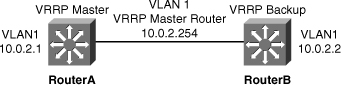
![]() Example 5-20 illustrates a user configuring and verifying VRRP on Router A and Router B for the scenario, as shown in Figure 5-43.
Example 5-20 illustrates a user configuring and verifying VRRP on Router A and Router B for the scenario, as shown in Figure 5-43.
Enter configuration commands, one per line. End with CNTL/Z.
RouterA(config)# interface vlan 1
RouterA(config-if)# ip address 10.0.2.1 255.255.255.0
RouterA(config-if)# vrrp 1 ip 10.0.2.254
RouterA(config-if)# vrrp 1 timers advertise msec 500
RouterA(config-if)# end
RouterB# configure terminal
Enter configuration commands, one per line. End with CNTL/Z.
RouterB(config)# interface vlan 1
RouterB(config-if)# ip address 10.0.2.2 255.255.255.0
RouterB(config-if)# vrrp 1 ip 10.0.2.254
RouterB(config-if)# vrrp 1 priority 90
RouterB(config-if)# vrrp 1 timers learn
RouterB(config-if)# end
RouterA# show vrrp interface vlan 1
Vlan1 - Group 1
State is Master
Virtual IP address is 10.0.2.254
Virtual MAC address is 0000.5e00.0101
Advertisement interval is 0.500 sec
Preemption is enabled
min delay is 0.000 sec
Priority is 100
Master Router is 10.0.2.1 (local), priority is 100
Master Advertisement interval is 0.500 sec
Master Down interval is 2.109 sec
RouterB# show vrrp interface vlan 1
Vlan1 - Group 1
State is Backup
Virtual IP address is 10.0.2.254
Virtual MAC address is 0000.5e00.0101
Advertisement interval is 0.500 sec
Preemption is enabled
min delay is 0.000 sec
Priority is 90
Authentication is enabled
Master Router is 10.0.2.1, priority is 100
Master Advertisement interval is 0.500 sec
Master Down interval is 2.109 sec (expires in 1.745 sec)
![]() A main difference between HSRP and VRRP is that in VRRP, the backup router does not send advertisements. Therefore, as shown in Example 5-20, the VRRP master is not aware of the current backup router.
A main difference between HSRP and VRRP is that in VRRP, the backup router does not send advertisements. Therefore, as shown in Example 5-20, the VRRP master is not aware of the current backup router.
Gateway Load Balancing Protocol
![]() Although HSRP and VRRP provide gateway resiliency, for the standby members of the redundancy group, the upstream bandwidth is not used while the device is in standby mode.
Although HSRP and VRRP provide gateway resiliency, for the standby members of the redundancy group, the upstream bandwidth is not used while the device is in standby mode.
![]() Only the active router for HSRP and VRRP groups forwards traffic for the virtual MAC. Resources associated with the standby router are not fully utilized. Some load balancing can be accomplished with these protocols through the creation of multiple groups and through the assignment of multiple default gateways, but this configuration creates an administrative burden.
Only the active router for HSRP and VRRP groups forwards traffic for the virtual MAC. Resources associated with the standby router are not fully utilized. Some load balancing can be accomplished with these protocols through the creation of multiple groups and through the assignment of multiple default gateways, but this configuration creates an administrative burden.
![]() GLBP is a Cisco-proprietary solution created to enable automatic selection and simultaneous use of multiple available gateways in addition to automatic failover between those gateways. Multiple routers share the load of frames that, from a client perspective, are sent to a single default gateway address.
GLBP is a Cisco-proprietary solution created to enable automatic selection and simultaneous use of multiple available gateways in addition to automatic failover between those gateways. Multiple routers share the load of frames that, from a client perspective, are sent to a single default gateway address.
![]() With GLBP, resources can be fully utilized without the administrative burden of configuring multiple groups and managing multiple default gateway configurations, as is required with HSRP and VRRP. Table 5-11 compares HSRP and GLBP protocols.
With GLBP, resources can be fully utilized without the administrative burden of configuring multiple groups and managing multiple default gateway configurations, as is required with HSRP and VRRP. Table 5-11 compares HSRP and GLBP protocols.
|
| |
|---|---|
|
|
|
|
|
|
|
|
|
|
|
|
|
|
|
|
|
|
|
|
|
|
|
|
|
|
|
![]() HSRP is typically used in Cisco networks as usually there are only two gateways for any subnet. GLBP can be used if more than two gateways exist for subnets to load share across the gateways.
HSRP is typically used in Cisco networks as usually there are only two gateways for any subnet. GLBP can be used if more than two gateways exist for subnets to load share across the gateways.
GLBP Functions
![]() The following are the GLBP functions:
The following are the GLBP functions:
- GLBP active virtual gateway (AVG): Members of a GLBP group elect one gateway to be the AVG for that group. Other group members provide backup for the AVG if the AVG becomes unavailable. The AVG assigns a virtual MAC address to each member of the GLBP group.
- GLBP active virtual forwarder (AVF): Each gateway assumes responsibility for forwarding packets that are sent to the virtual MAC address assigned to that gateway by the AVG. These gateways are known as AVFs for their virtual MAC address.
- GLBP communication: GLBP members communicate between each other through hello messages sent every 3 seconds to the multicast address 224.0.0.102, User Datagram Protocol (UDP) port 3222.
![]() In Figure 5-44, Router A is acting as the AVG. Router A has assigned virtual MAC 0007.b400.0101 to itself and Router B is acting as AVF for the virtual Mac 0007.b400.0102 assigned to it by Router A. Client 1 default gateway is Router A and Client 2 default gateway is Router B based on the virtual MAC assignment.
In Figure 5-44, Router A is acting as the AVG. Router A has assigned virtual MAC 0007.b400.0101 to itself and Router B is acting as AVF for the virtual Mac 0007.b400.0102 assigned to it by Router A. Client 1 default gateway is Router A and Client 2 default gateway is Router B based on the virtual MAC assignment.


GLBP Features
![]() The following are the features of GLBP:
The following are the features of GLBP:
- Load sharing: You can configure GLBP in such a way that multiple routers can share traffic from LAN clients, thereby sharing the traffic load more equitably among available routers.
- Multiple virtual routers: GLBP supports up to 1024 virtual routers (GLBP groups) on each physical interface of a router and up to four virtual forwarders per group.
- Preemption: The redundancy scheme of GLBP enables you to preempt an AVG with a higher priority backup virtual gateway that has become available. Forwarder preemption works in a similar way, except that forwarder preemption uses weighting instead of priority and is enabled by default.
- Efficient resource utilization: GLBP makes it possible for any router in a group to serve as a backup, which eliminates the need for a dedicated backup router because all available routers can support network traffic.
![]() GLBP provides upstream load sharing by utilizing the redundant uplinks simultaneously. It uses link capacity efficiently, thus providing peak-load traffic coverage. By making use of multiple available paths upstream from the routers or Layer 3 switches running GLBP, output queues may also be reduced.
GLBP provides upstream load sharing by utilizing the redundant uplinks simultaneously. It uses link capacity efficiently, thus providing peak-load traffic coverage. By making use of multiple available paths upstream from the routers or Layer 3 switches running GLBP, output queues may also be reduced.
![]() Only a single path is used with HSRP or VRRP, while others are idle, unless multiple groups and gateways are configured. The single path may encounter higher output queue rates during peak times, which leads to lower performance from higher jitter rates. The impact of jitter is lessened and overall performance is increased because more upstream bandwidth is available, and additional upstream paths are used.
Only a single path is used with HSRP or VRRP, while others are idle, unless multiple groups and gateways are configured. The single path may encounter higher output queue rates during peak times, which leads to lower performance from higher jitter rates. The impact of jitter is lessened and overall performance is increased because more upstream bandwidth is available, and additional upstream paths are used.
GLBP Operations
![]() GLBP allows automatic selection and simultaneous use of all available gateways in the group. The members of a GLBP group elect one gateway to be the AVG for that group. Other members of the group provide backup for the AVG if it becomes unavailable. The AVG assigns a virtual MAC address to each member of the GLBP group. All routers become AVFs for frames addressed to that virtual MAC address. As clients send Address Resolution Protocol (ARP) requests for the address of the default gateway, the AVG sends these virtual MAC addresses in the ARP replies. A GLBP group can have up to four group members.
GLBP allows automatic selection and simultaneous use of all available gateways in the group. The members of a GLBP group elect one gateway to be the AVG for that group. Other members of the group provide backup for the AVG if it becomes unavailable. The AVG assigns a virtual MAC address to each member of the GLBP group. All routers become AVFs for frames addressed to that virtual MAC address. As clients send Address Resolution Protocol (ARP) requests for the address of the default gateway, the AVG sends these virtual MAC addresses in the ARP replies. A GLBP group can have up to four group members.
![]() GLBP supports these operational modes for load balancing traffic across multiple default routers servicing the same default gateway IP address:
GLBP supports these operational modes for load balancing traffic across multiple default routers servicing the same default gateway IP address:
- Weighted load-balancing algorithm: The amount of load directed to a router is dependent upon the weighting value advertised by that router.
- Host-dependent load-balancing algorithm: A host is guaranteed use of the same virtual MAC address as long as that virtual MAC address is participating in the GLBP group.
- Round-robin load-balancing algorithm: As clients send ARP requests to resolve the MAC address of the default gateway, the reply to each client contains the MAC address of the next possible router in round-robin fashion. All routers’ MAC addresses take turns being included in address resolution replies for the default gateway IP address.
![]() GLBP automatically manages the virtual MAC address assignment, determines who handles the forwarding, and ensures that each station has a forwarding path if failures to gateways or tracked interfaces occur. If failures occur, the load-balancing ratio is adjusted among the remaining AVFs so that resources are used in the most efficient way.
GLBP automatically manages the virtual MAC address assignment, determines who handles the forwarding, and ensures that each station has a forwarding path if failures to gateways or tracked interfaces occur. If failures occur, the load-balancing ratio is adjusted among the remaining AVFs so that resources are used in the most efficient way.
![]() As shown in Figure 5-45, by default, GLBP attempts to balance traffic on a per-host basis using the round-robin algorithm. When a client sends an ARP message for the gateway IP address, the AVG returns the virtual MAC address of one of the AVFs. When a second client sends an ARP message, the AVG returns the next virtual MAC address from the list.
As shown in Figure 5-45, by default, GLBP attempts to balance traffic on a per-host basis using the round-robin algorithm. When a client sends an ARP message for the gateway IP address, the AVG returns the virtual MAC address of one of the AVFs. When a second client sends an ARP message, the AVG returns the next virtual MAC address from the list.


![]() Having each resolved a different MAC address for the default gateway, Clients A and B send their routed traffic to separate routers, as shown in Figure 5-46, although they both have the same default gateway address configured. Each GLBP router is an AVF for the virtual MAC address to which it has been assigned.
Having each resolved a different MAC address for the default gateway, Clients A and B send their routed traffic to separate routers, as shown in Figure 5-46, although they both have the same default gateway address configured. Each GLBP router is an AVF for the virtual MAC address to which it has been assigned.


GLBP Interface Tracking
![]() Like HSRP, GLBP can be configured to track interfaces. In Figure 5-47, the WAN link from Router R1 is lost. GLBP detects the failure. Just like HSRP, GLBP decrements the gateway priority when a tracked interface fails. The second gateway then becomes primary. This transition is transparent for the LAN client.
Like HSRP, GLBP can be configured to track interfaces. In Figure 5-47, the WAN link from Router R1 is lost. GLBP detects the failure. Just like HSRP, GLBP decrements the gateway priority when a tracked interface fails. The second gateway then becomes primary. This transition is transparent for the LAN client.


![]() Because interface tracking was configured on R1, the job of forwarding packets for virtual MAC address 0000.0000.0001 will be taken over by the secondary virtual forwarder for the MAC, Router R2. Therefore, the client sees no disruption of service nor does the client need to resolve a new MAC address for the default gateway, as shown in Figure 5-48.
Because interface tracking was configured on R1, the job of forwarding packets for virtual MAC address 0000.0000.0001 will be taken over by the secondary virtual forwarder for the MAC, Router R2. Therefore, the client sees no disruption of service nor does the client need to resolve a new MAC address for the default gateway, as shown in Figure 5-48.


![]() GLBP weighting determines whether a router can act as a virtual forwarder. Initial weighting values can be set and optional thresholds specified. Interface states can be tracked and a decrement value set to reduce the weighting value if the interface goes down. When the GLBP router weighting drops below a specified value, the router will no longer be an active virtual forwarder. When the weighting rises above a specified value, the router can resume its role as an active virtual forwarder.
GLBP weighting determines whether a router can act as a virtual forwarder. Initial weighting values can be set and optional thresholds specified. Interface states can be tracked and a decrement value set to reduce the weighting value if the interface goes down. When the GLBP router weighting drops below a specified value, the router will no longer be an active virtual forwarder. When the weighting rises above a specified value, the router can resume its role as an active virtual forwarder.
![]() The GLBP weighting mechanism is different from HSRP or VRRP. With HSRP and VRRP, one single threshold is defined. If the router priority (or weight) falls below the threshold, the router loses its active state. As soon as the router weight (or priority) exceeds the threshold, the router regains its active state. With GLBP, two thresholds are defined: one lower threshold that applies when the router loses weight, and one upper threshold that applies when the router regains weight. This double threshold mechanism enables more flexibility than the single threshold system.
The GLBP weighting mechanism is different from HSRP or VRRP. With HSRP and VRRP, one single threshold is defined. If the router priority (or weight) falls below the threshold, the router loses its active state. As soon as the router weight (or priority) exceeds the threshold, the router regains its active state. With GLBP, two thresholds are defined: one lower threshold that applies when the router loses weight, and one upper threshold that applies when the router regains weight. This double threshold mechanism enables more flexibility than the single threshold system.
![]() In Figure 5-49, SW4 is forwarding. Its initial weight (or priority) is 110. SW4 tracks both fa0/23 and fa0/24 interfaces. Fa0/23 is the active interface. Losing fa0/23 decrements SW4 by 20 points, thus bringing SW4 weight down (from 110) to 90. Fa0/24 is a backup interface. Losing fa0/24 decrements SW4 by 10 points, thus bringing SW4 weight down (from 110) to 100, which is the default weight of the other routers. Losing both fa0/23 and fa0/24 brings SW4 weight down (from 110) to 80.
In Figure 5-49, SW4 is forwarding. Its initial weight (or priority) is 110. SW4 tracks both fa0/23 and fa0/24 interfaces. Fa0/23 is the active interface. Losing fa0/23 decrements SW4 by 20 points, thus bringing SW4 weight down (from 110) to 90. Fa0/24 is a backup interface. Losing fa0/24 decrements SW4 by 10 points, thus bringing SW4 weight down (from 110) to 100, which is the default weight of the other routers. Losing both fa0/23 and fa0/24 brings SW4 weight down (from 110) to 80.


![]() In Figure 5-49, losing fa0/24 brings SW4 weight to the same level as the other. If an election occurs, SW4 might or might not be the AVG but would still forward. Losing fa0/23 brings SW4 weight below the other routers weight. If an election occurs, SW4 would not be elected as AVG but would still be an AVF. The lower threshold is set to 85, which can be reached only by losing either fa0/23 or fa0/24. In other words, losing fa0/23 or fa0/24 decreases SW4 weight, and might change its status from AVG to AVF, but will not prevent SW4 from being a forwarder. It is only when both interfaces are lost that SW4 stops forwarding.
In Figure 5-49, losing fa0/24 brings SW4 weight to the same level as the other. If an election occurs, SW4 might or might not be the AVG but would still forward. Losing fa0/23 brings SW4 weight below the other routers weight. If an election occurs, SW4 would not be elected as AVG but would still be an AVF. The lower threshold is set to 85, which can be reached only by losing either fa0/23 or fa0/24. In other words, losing fa0/23 or fa0/24 decreases SW4 weight, and might change its status from AVG to AVF, but will not prevent SW4 from being a forwarder. It is only when both interfaces are lost that SW4 stops forwarding.
![]() Losing one interface is an issue but does not prevent SW4 from forwarding. Losing both interfaces is the sign of a major connectivity problem in the network. For that reason, the network administrator decided that if SW4 lost both interfaces, it would not resume forwarding until both interfaces are back up. To implement this mechanism, the second threshold, the upper threshold, is set to 105. As long as SW4 weight does not go below the lower threshold (85), the upper threshold is not called. As soon as SW4 goes below the lower threshold, SW4 stops forwarding and the upper threshold is called. It is only then when SW4 weight will become higher than the upper threshold that SW4 will resume forwarding packets.
Losing one interface is an issue but does not prevent SW4 from forwarding. Losing both interfaces is the sign of a major connectivity problem in the network. For that reason, the network administrator decided that if SW4 lost both interfaces, it would not resume forwarding until both interfaces are back up. To implement this mechanism, the second threshold, the upper threshold, is set to 105. As long as SW4 weight does not go below the lower threshold (85), the upper threshold is not called. As soon as SW4 goes below the lower threshold, SW4 stops forwarding and the upper threshold is called. It is only then when SW4 weight will become higher than the upper threshold that SW4 will resume forwarding packets.
![]() In this scenario, when both interfaces are lost, SW4 goes below the lower threshold (85) to reach 80. Recovering fa0/23 or fa0/24 would add 20 or 10 points to the weight, but each interface weight is not enough to have SW4 exceed the upper threshold, 105. It is only when both interfaces get reenabled that the weight exceeds the upper threshold and that SW4 resumes forwarding packets. The configuration for this scenario is shown in Figure 5-50.
In this scenario, when both interfaces are lost, SW4 goes below the lower threshold (85) to reach 80. Recovering fa0/23 or fa0/24 would add 20 or 10 points to the weight, but each interface weight is not enough to have SW4 exceed the upper threshold, 105. It is only when both interfaces get reenabled that the weight exceeds the upper threshold and that SW4 resumes forwarding packets. The configuration for this scenario is shown in Figure 5-50.


GLBP Configuration
![]() Table 5-12 describes the steps needed to configure GLBP, and Figure 5-50 shows a sample configuration for the scenario presented in Figure 5-49.
Table 5-12 describes the steps needed to configure GLBP, and Figure 5-50 shows a sample configuration for the scenario presented in Figure 5-49.
|
|
|
|---|---|
|
|
|
|
|
|
|
|
|
GLBP with VLAN Spanning Across Access Layer Switches
![]() Figure 5-51 depicts a topology in which STP has blocked one of the access uplinks, and this might result in a two-hop path at Layer 2 for upstream traffic when GLBP is configured at the distribution layer. In the example in Figure 5-51, Distribution A switch has a direct connection to the core and a redundant link to Distribution B. Because of spanning-tree operations, the interface directly linking to the core is in blocking state. Although invisible and transparent to VLAN 2 clients, this state results in the frames coming from VLAN 2 to transit through Distribution A and then actually go through Distribution B before being sent to the core.
Figure 5-51 depicts a topology in which STP has blocked one of the access uplinks, and this might result in a two-hop path at Layer 2 for upstream traffic when GLBP is configured at the distribution layer. In the example in Figure 5-51, Distribution A switch has a direct connection to the core and a redundant link to Distribution B. Because of spanning-tree operations, the interface directly linking to the core is in blocking state. Although invisible and transparent to VLAN 2 clients, this state results in the frames coming from VLAN 2 to transit through Distribution A and then actually go through Distribution B before being sent to the core.


![]() In environments in which VLANs span across switches, HSRP is the recommended first hop redundancy protocol implementation. In all cases, the active gateway should be configured to also be the root bridge for the VLAN in which first hop redundancy is configured.
In environments in which VLANs span across switches, HSRP is the recommended first hop redundancy protocol implementation. In all cases, the active gateway should be configured to also be the root bridge for the VLAN in which first hop redundancy is configured.
0 comments
Post a Comment