Configuring a Cisco IOS Zone-Based Policy Firewall
![]() Zone-based policy firewalls change the original implementation of Cisco IOS Classic Firewall stateful inspection from the older interface-based model to a more flexible, more easily understood zone-based configuration model. This section focuses on the features of Cisco IOS zone-based policy firewalls and how to use the Cisco Router and Security Device Manager (SDM) to configure them.
Zone-based policy firewalls change the original implementation of Cisco IOS Classic Firewall stateful inspection from the older interface-based model to a more flexible, more easily understood zone-based configuration model. This section focuses on the features of Cisco IOS zone-based policy firewalls and how to use the Cisco Router and Security Device Manager (SDM) to configure them.
 Zone-Based Policy Firewall Overview
![]() The original implementation of Cisco IOS Classic Firewall stateful inspection used an interface-based configuration model, in which a stateful inspection policy was applied to an interface. All traffic passing through that interface received the same inspection policy. This configuration model limited the granularity of the firewall policies and caused confusion of the proper application of firewall policies, particularly in scenarios when firewall policies must be applied between multiple interfaces.
The original implementation of Cisco IOS Classic Firewall stateful inspection used an interface-based configuration model, in which a stateful inspection policy was applied to an interface. All traffic passing through that interface received the same inspection policy. This configuration model limited the granularity of the firewall policies and caused confusion of the proper application of firewall policies, particularly in scenarios when firewall policies must be applied between multiple interfaces.
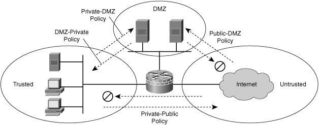
![]() Zone-based policy firewall (sometimes referred to as ZBF, or zone-policy firewall [ZPF]) changes the firewall from the older interface-based model to a more flexible, more easily understood zone-based configuration model. Interfaces are assigned to zones, and an inspection policy is applied to traffic moving between the zones, as shown in Figure 3-32. Figure 3-32 shows three zones:
Zone-based policy firewall (sometimes referred to as ZBF, or zone-policy firewall [ZPF]) changes the firewall from the older interface-based model to a more flexible, more easily understood zone-based configuration model. Interfaces are assigned to zones, and an inspection policy is applied to traffic moving between the zones, as shown in Figure 3-32. Figure 3-32 shows three zones:
-
 DMZ: Contains the corporate servers access from the public
 -
 Trusted: Represents the inside network
![]() Interzone policies offer considerable flexibility and granularity, and thus enable you to apply different inspection policies to multiple host groups that are connected to the same router interface. The policies on Figure 3-32 are as follows:
Interzone policies offer considerable flexibility and granularity, and thus enable you to apply different inspection policies to multiple host groups that are connected to the same router interface. The policies on Figure 3-32 are as follows:
-
 Public: DMZ policy that sets the rules for traffic originating from the untrusted zone with the DMZ as destination
 -
 DMZ: Private policy that sets the rules for the traffic originating from the DMZ with the trusted zone as destination
 -
 Private: DMZ policy that sets the rules for the traffic originating from the trusted zone with the DMZ as destination
 -
 Private: Pubic policy that sets the rules for the traffic originating from the trusted zone with the untrusted zone as destination
![]() Zone-based policy firewalls are configured with the Cisco Common Classification Policy Language (C3PL), which uses a hierarchical structure to define inspection for network protocols and the groups of hosts to which the inspection will be applied.
Zone-based policy firewalls are configured with the Cisco Common Classification Policy Language (C3PL), which uses a hierarchical structure to define inspection for network protocols and the groups of hosts to which the inspection will be applied.
| Key Topic |
|
![]() First-generation firewalls, packet filters, used only ACLs to control traffic. For this reason, it was relatively easy for attackers to breach a firewall, because no state data was examined. Second-generation firewalls, proxy firewalls, were concerned with the state of the connection, but they were application dependent. Third-generation firewalls, stateful packet filters, were developed to provide state tracking, application independence, and speed. Context-Based Access Control (CBAC), from the legacy Cisco IOS Firewall feature set, is an example of this type of third-generation firewall.
First-generation firewalls, packet filters, used only ACLs to control traffic. For this reason, it was relatively easy for attackers to breach a firewall, because no state data was examined. Second-generation firewalls, proxy firewalls, were concerned with the state of the connection, but they were application dependent. Third-generation firewalls, stateful packet filters, were developed to provide state tracking, application independence, and speed. Context-Based Access Control (CBAC), from the legacy Cisco IOS Firewall feature set, is an example of this type of third-generation firewall.
![]() CBAC performs traffic filtering based on application-level protocol information. It does this filtering using stateful filters, whereby selected outbound traffic creates a temporary opening in the filter for replies to return through. This capability means that CBAC examines more than transport layer TCP or UDP ports. With FTP, it tracks the application as it opens ports for data connections, and allows the replies back through the firewall. With UDP, it tracks application ports and allows replies. With other application protocols, it tracks multiple connections that are created by negotiation on a control channel. Multimedia protocols, SQL*Net, and Remote Procedure Call (RPC) are examples of such traffic. CBAC can also perform Java blocking, based on server address. It does not perform Java or ActiveX content filtering.
CBAC performs traffic filtering based on application-level protocol information. It does this filtering using stateful filters, whereby selected outbound traffic creates a temporary opening in the filter for replies to return through. This capability means that CBAC examines more than transport layer TCP or UDP ports. With FTP, it tracks the application as it opens ports for data connections, and allows the replies back through the firewall. With UDP, it tracks application ports and allows replies. With other application protocols, it tracks multiple connections that are created by negotiation on a control channel. Multimedia protocols, SQL*Net, and Remote Procedure Call (RPC) are examples of such traffic. CBAC can also perform Java blocking, based on server address. It does not perform Java or ActiveX content filtering.
![]() The inspection by CBAC also allows it to prevent certain DoS attacks. For example, it detects and prevents SYN flooding, badly out of sequence TCP packets, large numbers of half-open connections, and high rates of new connections.
The inspection by CBAC also allows it to prevent certain DoS attacks. For example, it detects and prevents SYN flooding, badly out of sequence TCP packets, large numbers of half-open connections, and high rates of new connections.
| Note |
|
![]() The legacy stateful inspection done by CBAC was very complicated because there was a combination of ACLs and inspection rules, all of which worked together to accomplish the stateful packet filtering done by the firewall.
The legacy stateful inspection done by CBAC was very complicated because there was a combination of ACLs and inspection rules, all of which worked together to accomplish the stateful packet filtering done by the firewall.
![]() The Cisco IOS zone-based policy firewall completely changes the way you configure a Cisco IOS Firewall.
The Cisco IOS zone-based policy firewall completely changes the way you configure a Cisco IOS Firewall.
![]() The first major change to the firewall configuration is the introduction of a zone-based configuration. A Cisco IOS Firewall is the first Cisco IOS Software threat defense feature to implement a zone configuration model. Other features will adopt the zone model over time.
The first major change to the firewall configuration is the introduction of a zone-based configuration. A Cisco IOS Firewall is the first Cisco IOS Software threat defense feature to implement a zone configuration model. Other features will adopt the zone model over time.
![]() The classic Cisco IOS Firewall stateful inspection (CBAC) interface-based configuration model that you can configure using the ip inspect command will be maintained for a period of time, but few, if any, new features will be available.
The classic Cisco IOS Firewall stateful inspection (CBAC) interface-based configuration model that you can configure using the ip inspect command will be maintained for a period of time, but few, if any, new features will be available.
![]() A Cisco IOS zone-based policy firewall does not use the stateful inspection (CBAC) commands. You can use the two configuration models concurrently on routers but not on the same interfaces; you cannot configure an interface as a security zone member and for ip inspect simultaneously.
A Cisco IOS zone-based policy firewall does not use the stateful inspection (CBAC) commands. You can use the two configuration models concurrently on routers but not on the same interfaces; you cannot configure an interface as a security zone member and for ip inspect simultaneously.
![]() Zones establish the security borders of your network. A zone defines a boundary where traffic is subjected to policy restrictions as it crosses to another region of your network. The default policy of a zone-policy firewall between zones is to “deny all.” If no policy is explicitly configured, all traffic moving between zones is blocked. This policy is a significant departure from the stateful inspection model, in which traffic is implicitly allowed unless it is explicitly blocked with an ACL entry.
Zones establish the security borders of your network. A zone defines a boundary where traffic is subjected to policy restrictions as it crosses to another region of your network. The default policy of a zone-policy firewall between zones is to “deny all.” If no policy is explicitly configured, all traffic moving between zones is blocked. This policy is a significant departure from the stateful inspection model, in which traffic is implicitly allowed unless it is explicitly blocked with an ACL entry.
![]() The second major change is the introduction of a new configuration policy language known as C3PL. The C3PL structure is similar to the modular QoS CLI (MQC) structure in which class maps specify the traffic that is affected by the action that the policy map applies.
The second major change is the introduction of a new configuration policy language known as C3PL. The C3PL structure is similar to the modular QoS CLI (MQC) structure in which class maps specify the traffic that is affected by the action that the policy map applies.
| Note |
|
Zone-Based Policy Firewall Actions
![]() The Cisco IOS zone-based policy firewall can take three possible actions when you configure it using Cisco SDM:
The Cisco IOS zone-based policy firewall can take three possible actions when you configure it using Cisco SDM:
-
 Inspect: This action configures Cisco IOS stateful packet inspection.
 -
 Drop: This action is analogous to deny in an ACL.
 -
 Pass: This action is analogous to permit in an ACL. The pass action does not track the state of connections or sessions within the traffic; pass allows the traffic only in one direction. A corresponding policy must be applied to allow return traffic to pass in the opposite direction.
| Note |
|
Zone-Based Policy Firewall: Rule for Application Traffic
![]() The membership of the router network interfaces in zones is subject to several rules governing interface behavior, as is the traffic moving between zone member interfaces:
The membership of the router network interfaces in zones is subject to several rules governing interface behavior, as is the traffic moving between zone member interfaces:
-
 A zone must be configured before you can assign interfaces to the zone.
 -
 You can assign an interface to only one security zone.
 -
 Traffic is implicitly allowed to flow by default among interfaces that are members of the same zone.
 -
 To permit traffic to and from a zone member interface, a policy allowing or inspecting traffic must be configured between that zone and any other zone.
 -
 Traffic cannot flow between a zone member interface and any interface that is not a zone member. You can apply pass, inspect, and drop actions only between two zones.
 -
 Interfaces that have not been assigned to a zone function as classical router ports and might still use classical stateful inspection (CBAC) configuration.
 -
 If you do not want an interface on the router to be part of the zone-based firewall policy, it might still be necessary to put that interface in a zone and configure a “pass all” policy (sort of a dummy policy) between that zone and any other zone to which traffic flow is desired.
 -
 From the preceding rules it follows that if traffic is to flow among all the interfaces in a router, all the interfaces must be part of the zoning model (each interface must be a member of a zone).
![]() Table 3-7 shows a number of examples of different interface and configuration combinations.
Table 3-7 shows a number of examples of different interface and configuration combinations.
|
|
|
|
|
|
|---|---|---|---|---|
|
|
|
|
|
|
|
|
|
|
|
|
|
|
|
|
|
|
|
|
|
|
|
|
|
|
|
|
|
|
|
|
|
|
|
|
|
|
|
|
|
|
Zone-Based Policy Firewall: Rule for Router Traffic
![]() The rules for a zone-based policy firewall are different when the router is involved in the traffic flow, whether as the source of traffic or the destination. A zone-based policy firewall is used to control router administration where the router is the destination. Table 3-8 illustrates various scenarios that involve traffic in or out of the router.
The rules for a zone-based policy firewall are different when the router is involved in the traffic flow, whether as the source of traffic or the destination. A zone-based policy firewall is used to control router administration where the router is the destination. Table 3-8 illustrates various scenarios that involve traffic in or out of the router.
|
|
|
|
|
|
|---|---|---|---|---|
|
|
|
|
|
|
|
|
|
|
|
|
|
|
|
|
|
|
|
|
|
|
|
|
|
|
|
|
|
|
|
|
|
|
|
|
![]() When an interface is configured to be a zone member, the hosts connected to the interface are included in the zone, but traffic flowing to and from the interfaces of the router is not controlled by the zone policies. Instead, all the IP interfaces on the router are automatically made part of the “self” zone when a zone-based policy firewall is configured. To limit IP traffic moving to the IP addresses of the router from the various zones on a router, policies must be applied to block, allow, or inspect traffic between the zone and the self zone of the router, and vice versa. If there are no policies between a zone and the self zone, all traffic is permitted to the interfaces of the router without being inspected.
When an interface is configured to be a zone member, the hosts connected to the interface are included in the zone, but traffic flowing to and from the interfaces of the router is not controlled by the zone policies. Instead, all the IP interfaces on the router are automatically made part of the “self” zone when a zone-based policy firewall is configured. To limit IP traffic moving to the IP addresses of the router from the various zones on a router, policies must be applied to block, allow, or inspect traffic between the zone and the self zone of the router, and vice versa. If there are no policies between a zone and the self zone, all traffic is permitted to the interfaces of the router without being inspected.
![]() If desired, you can define a policy using the self zone as either the source or destination zone. The self zone is a system-defined zone. It does not require any interfaces to be configured as members. A zone pair that includes the self zone, along with the associated policy, applies to traffic that is directed to the router or traffic that the router generates. It does not apply to traffic traversing the router.
If desired, you can define a policy using the self zone as either the source or destination zone. The self zone is a system-defined zone. It does not require any interfaces to be configured as members. A zone pair that includes the self zone, along with the associated policy, applies to traffic that is directed to the router or traffic that the router generates. It does not apply to traffic traversing the router.
![]() The following are additional rules for zone-based policy firewalls that govern interface behavior when the router is involved in the traffic flow:
The following are additional rules for zone-based policy firewalls that govern interface behavior when the router is involved in the traffic flow:
-
 All traffic to and from a given interface is implicitly blocked when the interface is assigned to a zone, except traffic to or from other interfaces in the same zone, and traffic to any interface on the router.
 -
 All the IP interfaces on the router are automatically made part of the “self” zone when a zone-based policy firewall is configured. The self zone is the only exception to the default deny-all policy. All traffic to any router interface is allowed until traffic is explicitly denied.
 -
 The only exception to the “deny by default” approach is the traffic to and from the router itself. This traffic is permitted by default. You can configure an explicit policy to restrict such traffic.
 Configuring Zone-Based Policy Firewalls Using the Basic Firewall Wizard
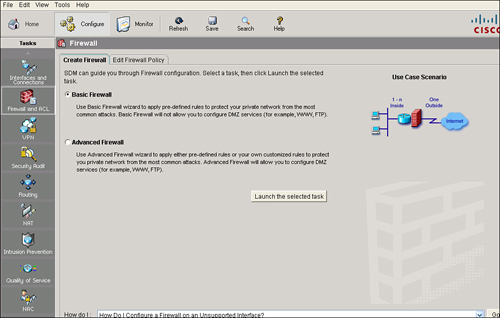
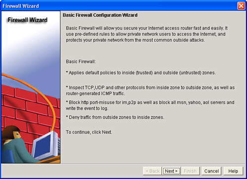
![]() The Basic Firewall Wizard of Cisco SDM helps you implement a firewall. The wizard walks you through creating the firewall by asking you for information about the interfaces on the router, whether you want to configure a demilitarized zone (DMZ) network, and what rules you want to use in the firewall, as shown in Figure 3-33.
The Basic Firewall Wizard of Cisco SDM helps you implement a firewall. The wizard walks you through creating the firewall by asking you for information about the interfaces on the router, whether you want to configure a demilitarized zone (DMZ) network, and what rules you want to use in the firewall, as shown in Figure 3-33.
![]() Follows these steps to configure a firewall using the Basic Firewall Wizard:
Follows these steps to configure a firewall using the Basic Firewall Wizard:
|
|
|
|
|
|
|
|
|
| Note |
|
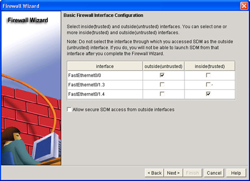
![]() The first task you must perform to configure a basic firewall is to define inside (trusted) and outside (untrusted) interfaces. An outside (untrusted) interface is typically the router interface that is connected to the Internet or to your WAN. An inside (trusted) interface is typically a physical or logical interface that connects to the LAN. You can select multiple inside and outside interfaces.
The first task you must perform to configure a basic firewall is to define inside (trusted) and outside (untrusted) interfaces. An outside (untrusted) interface is typically the router interface that is connected to the Internet or to your WAN. An inside (trusted) interface is typically a physical or logical interface that connects to the LAN. You can select multiple inside and outside interfaces.
![]() The following steps are used for interface configuration:
The following steps are used for interface configuration:
|
|
|
|
|
|
|
|
|
|
|
|
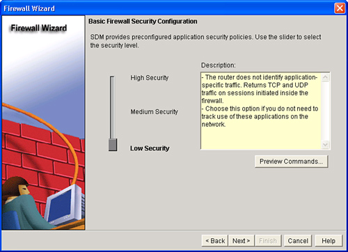
![]() The Basic Firewall Security Configuration window appears, as shown in Figure 3-36. Cisco SDM provides preconfigured application security policies that you can use to protect the network. Use the slider bar on the Basic Firewall Security Configuration window to choose the security level that you want and to view a description of the security that it provides.
The Basic Firewall Security Configuration window appears, as shown in Figure 3-36. Cisco SDM provides preconfigured application security policies that you can use to protect the network. Use the slider bar on the Basic Firewall Security Configuration window to choose the security level that you want and to view a description of the security that it provides.
![]() From the Basic Firewall Security Configuration window, you can click the Preview Commands button to view the Cisco IO commands that make up the chosen policy.
From the Basic Firewall Security Configuration window, you can click the Preview Commands button to view the Cisco IO commands that make up the chosen policy.
| Note |
|
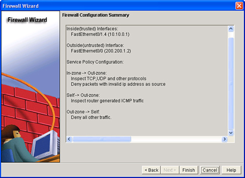
![]() The Firewall Configuration Summary window displays the policy name chosen, SDM_HIGH, SDM_MEDIUM, or SDM_LOW, and the configuration statements in the policy, as shown in Figure 3-37.
The Firewall Configuration Summary window displays the policy name chosen, SDM_HIGH, SDM_MEDIUM, or SDM_LOW, and the configuration statements in the policy, as shown in Figure 3-37.
![]() Example 3-14 shows the commands executed by the Basic Firewall Wizard.
Example 3-14 shows the commands executed by the Basic Firewall Wizard.
class-map type inspect match-any sdm-cls-insp-traffic
match protocol cuseeme
match protocol dns
match protocol ftp
match protocol h323
match protocol https
match protocol icmp
match protocol imap
match protocol pop3
match protocol netshow
match protocol shell
match protocol realmedia
match protocol rtsp
match protocol smtp extended
match protocol sql-net
match protocol streamworks
match protocol tftp
match protocol vdolive
match protocol tcp
match protocol udp
class-map type inspect match-all sdm-insp-traffic
match class-map sdm-cls-insp-traffic
class-map type inspect match-any SDM_EIGRP
match access-group name SDM_EIGRP
class-map type inspect match-any SDM_EIGRP_TRAFFIC
match class-map SDM_EIGRP
class-map type inspect match-all SDM_EIGRP_PT
match class-map SDM_EIGRP_TRAFFIC
class-map type inspect match-any sdm-cls-icmp-access
match protocol icmp
class-map type inspect match-all sdm-icmp-access
match class-map sdm-cls-icmp-access
class-map type inspect match-all sdm-invalid-src
match access-group 100
class-map type inspect match-all sdm-protocol-http
match protocol http
!
!
policy-map type inspect sdm-permit-icmpreply
class type inspect sdm-icmp-access
 inspect
class class-default
 pass
policy-map type inspect sdm-inspect
class type inspect sdm-invalid-src
 drop log
class type inspect sdm-insp-traffic
 inspect
class type inspect sdm-protocol-http
 inspect
class class-default
policy-map type inspect sdm-permit
class type inspect SDM_EIGRP_PT
 pass
class class-default
!
zone security out-zone
zone security in-zone
zone-pair security sdm-zp-self-out source self destination out-zone
service-policy type inspect sdm-permit-icmpreply
zone-pair security sdm-zp-out-self source out-zone destination self
service-policy type inspect sdm-permit
zone-pair security sdm-zp-in-out source in-zone destination out-zone
service-policy type inspect sdm-inspect
!
!
!
interface FastEthernet0/0
description $FW_INSIDE$
zone-member security in-zone
!
!
interface Serial0/0/0
description $FW_OUTSIDE$
zone-member security out-zone
!
!
ip access-list extended SDM_EIGRP
remark SDM_ACL Category=1
permit eigrp any any
!
access-list 100 remark SDM_ACL Category=128
access-list 100 permit ip host 255.255.255.255 any
access-list 100 permit ip 127.0.0.0 0.255.255.255 any
access-list 100 permit ip 192.168.151.0 0.0.0.3 any
!
 Manually Configuring Zone-Based Policy Firewalls Using Cisco SDM
![]() Cisco IOS zone-based policy firewalls are configured using C3PL, which uses a hierarchical structure to define inspection for network protocols and the groups of hosts to which the inspection applies.
Cisco IOS zone-based policy firewalls are configured using C3PL, which uses a hierarchical structure to define inspection for network protocols and the groups of hosts to which the inspection applies.
![]() There are four main steps to configure a Cisco IOS zone-based policy firewall:
There are four main steps to configure a Cisco IOS zone-based policy firewall:
|
|
|
|
|
|
|
|
|
|
|
|
![]() For a description of how you can implement a zone-based policy firewall, refer to the Zone-Based Policy Firewall Design Guide at Cisco.com.
For a description of how you can implement a zone-based policy firewall, refer to the Zone-Based Policy Firewall Design Guide at Cisco.com.
Step 1: Define Zones
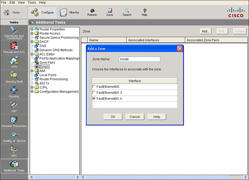
![]() The first step in configuring a Cisco IOS zone-based policy firewall is to create zones. A zone, or security zone, is a group of interfaces to which you can apply a security policy. The interfaces in a zone should share common functions or features. For example, you might place two interfaces that connect to the LAN in one security zone, and the interfaces that connect to the Internet into another security zone.
The first step in configuring a Cisco IOS zone-based policy firewall is to create zones. A zone, or security zone, is a group of interfaces to which you can apply a security policy. The interfaces in a zone should share common functions or features. For example, you might place two interfaces that connect to the LAN in one security zone, and the interfaces that connect to the Internet into another security zone.
![]() For traffic to flow among all the interfaces in a router, all the interfaces must be a member of a security zone. It is not necessary for all router interfaces to be members of security zones.
For traffic to flow among all the interfaces in a router, all the interfaces must be a member of a security zone. It is not necessary for all router interfaces to be members of security zones.
![]() Follow these steps to create a zone:
Follow these steps to create a zone:
|
|
|
|
|
|
|
|
|
|
|
|
|
|
|
![]() After a zone has been created, you can change the interfaces that are associated with the zone, but you cannot change the name of the zone. Click Edit from the Zone panel to choose different interfaces for an existing zone. Click Delete from the Zone panel to remove a zone.
After a zone has been created, you can change the interfaces that are associated with the zone, but you cannot change the name of the zone. Click Edit from the Zone panel to choose different interfaces for an existing zone. Click Delete from the Zone panel to remove a zone.
| Note |
|
Step 2: Define Class Maps
![]() The next step in configuring a Cisco IOS zone-based policy firewall is to configure the class maps. Class maps identify traffic and traffic parameters that a Cisco IOS zone-based policy firewall selects for policy application. The policy maps define the actions to be taken on the traffic. Configuring a class map involves associating the class map with some traffic and setting attributes for the traffic.
The next step in configuring a Cisco IOS zone-based policy firewall is to configure the class maps. Class maps identify traffic and traffic parameters that a Cisco IOS zone-based policy firewall selects for policy application. The policy maps define the actions to be taken on the traffic. Configuring a class map involves associating the class map with some traffic and setting attributes for the traffic.
![]() Layer 3/4 class maps sort the traffic based on the following criteria:
Layer 3/4 class maps sort the traffic based on the following criteria:
-
 Access group: A standard, extended, or named ACL can filter traffic based on source and destination IP addresses and source and destination ports.
 -
 Protocol: The class map can identify Layer 4 protocols such as TCP, UDP, and ICMP, and application services such as HTTP, SMTP, and DNS. Any well-known or user-defined service known to Port-to-Application Mapping (PAM) can be specified.
 -
 Class map: A subordinate class map that provides additional match criteria can be nested inside another class map.
![]() Class maps can apply “match-any” or “match-all” operators to determine how to apply the match criteria. If match-any is specified, traffic must meet only one of the match criteria in the class map. Match-any is a logical OR operation, a logical disjunction. If match-all is specified, traffic must match all the class map criteria to belong to that particular class. Match-all is a logical AND operation, a logical conjunction.
Class maps can apply “match-any” or “match-all” operators to determine how to apply the match criteria. If match-any is specified, traffic must meet only one of the match criteria in the class map. Match-any is a logical OR operation, a logical disjunction. If match-all is specified, traffic must match all the class map criteria to belong to that particular class. Match-all is a logical AND operation, a logical conjunction.
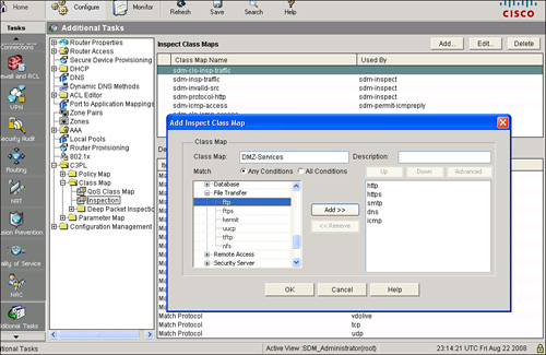
![]() To create a class map using Cisco SDM, choose Configure > Additional Tasks > C3PL > Class Map > Inspection, as shown in Figure 3-39. From the Inspect Class Maps panel, you can review, create, and edit class maps. The Class Map Name area of the window lists the configured class maps, and the lower portion of the window displays the details of the selected class map. If you need to edit a class map or see more detail about a class map, choose the class map from the list and click Edit.
To create a class map using Cisco SDM, choose Configure > Additional Tasks > C3PL > Class Map > Inspection, as shown in Figure 3-39. From the Inspect Class Maps panel, you can review, create, and edit class maps. The Class Map Name area of the window lists the configured class maps, and the lower portion of the window displays the details of the selected class map. If you need to edit a class map or see more detail about a class map, choose the class map from the list and click Edit.
| Note |
|
Step 3: Define Policy Maps
![]() Once you have created class maps, you create policy maps to which you apply class maps. Policy maps specify the actions to be taken when traffic matches the criteria. A policy map associates traffic classes with actions.
Once you have created class maps, you create policy maps to which you apply class maps. Policy maps specify the actions to be taken when traffic matches the criteria. A policy map associates traffic classes with actions.
![]() Inspection policy maps specify the action the router should take for traffic that matches the criteria in the associated class maps. The following are the actions a policy map supports:
Inspection policy maps specify the action the router should take for traffic that matches the criteria in the associated class maps. The following are the actions a policy map supports:
-
 Pass: Traffic is allowed to pass from one zone to another, only in one direction. The router does not monitor the state of connections or session.
 -
 Drop: The router drops unwanted traffic and can optionally log the event.
 -
 Inspect: The router maintains state-based session and connection information so that the router permits traffic returning from a destination zone to a source zone.
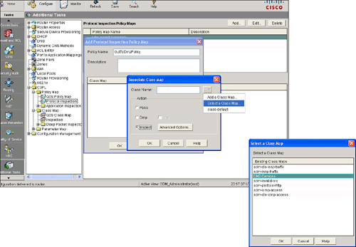
![]() Follow these steps to create a policy map using Cisco SDM:
Follow these steps to create a policy map using Cisco SDM:
|
|
|
|
|
|
|
|
|
|
|
|
|
|
|
|
|
|
|
|
|
|
|
|
|
|
|
Step 4: Define Zone Pairs and Assign Policy Maps to Zone Pairs
![]() A zone pair allows you to specify a unidirectional firewall policy between two security zones. The direction of the traffic is determined by specifying a source and destination security zone. The same zone cannot be defined as both the source and the destination.
A zone pair allows you to specify a unidirectional firewall policy between two security zones. The direction of the traffic is determined by specifying a source and destination security zone. The same zone cannot be defined as both the source and the destination.
![]() If you want traffic to flow in both directions between two zones, you must create a zone pair for each direction. If you want traffic to flow freely among all interfaces, each interface must be configured in a zone.
If you want traffic to flow in both directions between two zones, you must create a zone pair for each direction. If you want traffic to flow freely among all interfaces, each interface must be configured in a zone.
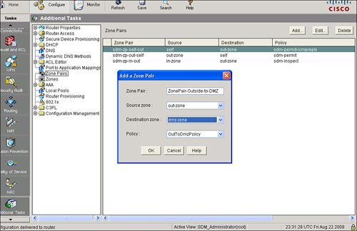
![]() Follow these steps to configure a new zone pair:
Follow these steps to configure a new zone pair:
|
|
|
|
|
|
|
|
|
|
|
|
![]() To edit a zone pair, from the Zone Pairs panel choose the zone pair you want to edit and click Edit. If you are editing a zone pair, you can change the policy map, but you cannot change the name or the source or destination zones.
To edit a zone pair, from the Zone Pairs panel choose the zone pair you want to edit and click Edit. If you are editing a zone pair, you can change the policy map, but you cannot change the name or the source or destination zones.
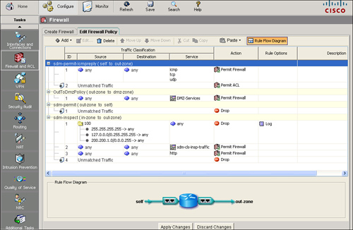
![]() After you have created the firewall, you can examine it by choosing Configure > Firewall and ACL and clicking the Edit Firewall Policy tab, as shown in Figure 3-42. A graphical view of the firewall displays in the context of the router interfaces. You can modify the firewall from this window if you need to.
After you have created the firewall, you can examine it by choosing Configure > Firewall and ACL and clicking the Edit Firewall Policy tab, as shown in Figure 3-42. A graphical view of the firewall displays in the context of the router interfaces. You can modify the firewall from this window if you need to.
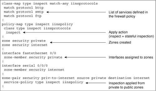
![]() Figure 3-43 shows, in a methodical manner, an example of what the resulting CLI commands might look like after configuring a Cisco IOS zone-based policy firewall that uses two interfaces and the default inspection parameters.
Figure 3-43 shows, in a methodical manner, an example of what the resulting CLI commands might look like after configuring a Cisco IOS zone-based policy firewall that uses two interfaces and the default inspection parameters.
![]() The class map named iinsprotocols is created and identifies three protocols that are to be inspected (HTTP, SMTP, and FTP). A policy map named iinspolicy is created that applies stateful inspection to the protocols that are listed in the iinsprotocols class map. Two zones, named private and internet, are created. Fastethernet0/0 is made a member of the private zone, and serial0/0/0 is made a member of the internet zone. Lastly, a zone pair named priv-to-internet is created with a source zone of private, a destination zone of “internet” zone, and the policy map named iinspolicy applied to it.
The class map named iinsprotocols is created and identifies three protocols that are to be inspected (HTTP, SMTP, and FTP). A policy map named iinspolicy is created that applies stateful inspection to the protocols that are listed in the iinsprotocols class map. Two zones, named private and internet, are created. Fastethernet0/0 is made a member of the private zone, and serial0/0/0 is made a member of the internet zone. Lastly, a zone pair named priv-to-internet is created with a source zone of private, a destination zone of “internet” zone, and the policy map named iinspolicy applied to it.
 Monitoring a Zone-Based-Firewall
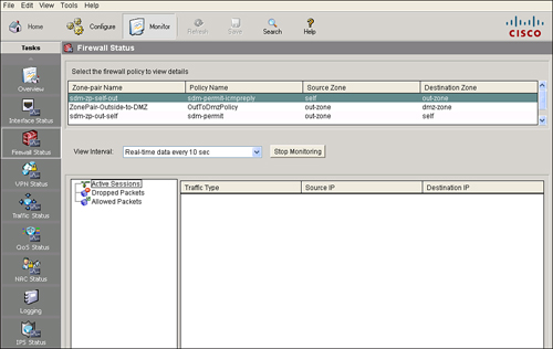
![]() If the router runs a Cisco IOS image that supports the zone-based policy firewall feature, you can use the Cisco SDM to display the status of the firewall activity for each zone pair configured on the router. To display the firewall status information, choose Monitor > Firewall Status, as shown in Figure 3-44.
If the router runs a Cisco IOS image that supports the zone-based policy firewall feature, you can use the Cisco SDM to display the status of the firewall activity for each zone pair configured on the router. To display the firewall status information, choose Monitor > Firewall Status, as shown in Figure 3-44.
![]() The firewall policy list area displays the policy name, source zone, and destination zone for each zone pair. From the View Interval list box, choose one of the following options to specify how data should be collected:
The firewall policy list area displays the policy name, source zone, and destination zone for each zone pair. From the View Interval list box, choose one of the following options to specify how data should be collected:
-
 Real-time data every 10 sec: Data is reported every 10 seconds. Each check mark on the horizontal axis of the Dropped Packets and Allowed Packets graph represents 10 seconds.
 -
 60 minutes of data polled every 1 minute: Data is collected every 1 minute, and the last 60 minutes result is displayed. Each check mark on the horizontal axis of the Dropped Packets and Allowed Packets graph represents 1 minute.
 -
 12 hours of data polled every 12 minutes: Data is reported every 12 minutes. Each check mark on the horizontal axis of the Dropped Packets and Allowed Packets graph represents 12 minutes.
![]() Use the show policy-map type inspect zone-pair session command to examine the active connections in the zone-based policy firewall state table.
Use the show policy-map type inspect zone-pair session command to examine the active connections in the zone-based policy firewall state table.
![]() Example 3-15 output shows active connections from 10.0.2.12 to 172.26.26.51 port 80.
Example 3-15 output shows active connections from 10.0.2.12 to 172.26.26.51 port 80.
R2# show policy-map type inspect zone-pair session
Zone-pair: IINS-PAIR
 Service-policy inspect : HTTP-Policy
   Class-map: HTTP-Class (match-all)
     Match: access-group 110
     Match: protocol http
     Inspect
       Established Sessions
        Session 643BCF88 (10.0.2.12:3364)=>(172.26.26.51:80) http SIS_OPEN
         Created 00:00:10, Last heard 00:00:00
         Bytes sent (initiator:responder) [1268:64324]
        Session 643BB9C8 (10.0.2.12:3361)=>(172.26.26.51:80) http SIS_OPEN
         Created 00:00:16, Last heard 00:00:06
         Bytes sent (initiator:responder) [2734:38447]
        Session 643BD240 (10.0.2.12:3362)=>(172.26.26.51:80) http SIS_OPEN
         Created 00:00:14, Last heard 00:00:07
         Bytes sent (initiator:responder) [2219:39813]
        Session 643BBF38 (10.0.2.12:3363)=>(172.26.26.51:80) http SIS_OPEN
         Created 00:00:14, Last heard 00:00:06
         Bytes sent (initiator:responder) [2106:19895]
   Class-map: class-default (match-any)
     Match: any
     Drop (default action)
       58 packets, 2104 bytes
Summary
![]() In this chapter, you have learned that a firewall is a set of rules designed to enforce an access control policy between two networks. You learned how to create firewall rules to implement your security policies. Cisco provides a range of firewall products that help you implement your security policies in a cost-effective way. ACLs provide packet-filtering capabilities for routers and firewalls to protect internal networks from the outside.
In this chapter, you have learned that a firewall is a set of rules designed to enforce an access control policy between two networks. You learned how to create firewall rules to implement your security policies. Cisco provides a range of firewall products that help you implement your security policies in a cost-effective way. ACLs provide packet-filtering capabilities for routers and firewalls to protect internal networks from the outside.
![]() A zone-based policy firewall changes the firewall from the older interface-based model to a more flexible, more easily understood zone-based configuration model. Cisco IOS zone-based policy firewalls provide a more flexible way to implement your security policy and Cisco Router and Security Device Manager (SDM) makes it easier for you to configure and maintain the firewall capabilities of your routers.
A zone-based policy firewall changes the firewall from the older interface-based model to a more flexible, more easily understood zone-based configuration model. Cisco IOS zone-based policy firewalls provide a more flexible way to implement your security policy and Cisco Router and Security Device Manager (SDM) makes it easier for you to configure and maintain the firewall capabilities of your routers.
 References
![]() For additional information, refer to these resources:
For additional information, refer to these resources:
-
 Deal, R. Cisco Router Firewall Security (Cisco Press, 2005)
 -
 Beaver, K. Firewall Best Practices, http://www.principlelogic.com/docs/Firewall_Best_Practices.pdf
 -
 Morgan, B. and N. Lovering. CCNP ISCW Official Exam Certification Guide (Cisco Press, 2007)
 -
 Cisco Systems, Inc. The Zone-Based Policy Firewall Design Guide, http://www.cisco.com/en/US/products/sw/secursw/ps1018/products_tech_note09186a00808bc994.shtml

0 comments
Post a Comment