Implementing Secure Management and Reporting
![]() In this section, you will learn the skills necessary to implement the management and reporting features of Cisco IOS devices, including the following technologies:
In this section, you will learn the skills necessary to implement the management and reporting features of Cisco IOS devices, including the following technologies:
-
 Syslog
 -
 Network Time Protocol (NTP)
 -
 Secure Shell (SSH)
 -
 Simple Network Management Protocol Version 3 (SNMPv3)
![]() In addition, you will examine some design aspects of a management infrastructure.
In addition, you will examine some design aspects of a management infrastructure.
 Planning Considerations for Secure Management and Reporting
![]() Configuring logging for your Cisco routers is a straightforward operation when your network contains only a few Cisco routers. However, logging and reading information from hundreds of devices can prove to be a challenging proposition and can raise the following issues and considerations:
Configuring logging for your Cisco routers is a straightforward operation when your network contains only a few Cisco routers. However, logging and reading information from hundreds of devices can prove to be a challenging proposition and can raise the following issues and considerations:
-
 What are the most important logs?
 -
 How are important messages separated from routine notifications?
 -
 How do you prevent tampering with logs?
 -
 How do you ensure that time stamps match?
 -
 What log data is needed in criminal investigations?
 -
 How do you deal with the volume of log messages?
 -
 How do you manage all the devices?
 -
 How can you track changes when attacks or network failures occur?
![]() Securing administrative access and device configurations is also a straightforward operation for smaller Cisco router networks. However, managing administrative access and device configurations for many devices can raise questions such as those listed.
Securing administrative access and device configurations is also a straightforward operation for smaller Cisco router networks. However, managing administrative access and device configurations for many devices can raise questions such as those listed.
![]() Each of these issues is specific to your needs. To identify the priorities of reporting and monitoring, you must get input from management and from the network and security teams. The security policy that you implement should also play a large role in answering these questions.
Each of these issues is specific to your needs. To identify the priorities of reporting and monitoring, you must get input from management and from the network and security teams. The security policy that you implement should also play a large role in answering these questions.
![]() From a reporting standpoint, most networking devices can send syslog data that can be invaluable when you are troubleshooting network problems or security threats. You can send this data to your syslog analysis host from any device whose logs you want to view. This data can be viewed in real time, on demand, and in scheduled reports. Depending on the device involved, you can choose various logging levels to ensure that the correct amount of data is sent to the logging device. You must also flag device log data within the analysis software to permit granular viewing and reporting. For example, during an attack, the log data that is provided by Layer 2 switches might not be as interesting as the data that is provided by the intrusion prevention system (IPS).
From a reporting standpoint, most networking devices can send syslog data that can be invaluable when you are troubleshooting network problems or security threats. You can send this data to your syslog analysis host from any device whose logs you want to view. This data can be viewed in real time, on demand, and in scheduled reports. Depending on the device involved, you can choose various logging levels to ensure that the correct amount of data is sent to the logging device. You must also flag device log data within the analysis software to permit granular viewing and reporting. For example, during an attack, the log data that is provided by Layer 2 switches might not be as interesting as the data that is provided by the intrusion prevention system (IPS).
![]() To ensure that log messages are synchronized with one another, clocks on hosts and network devices must be synchronized. For devices that support it, NTP provides a way to ensure that accurate time is kept on all devices. When you are dealing with an attack, seconds matter, because it is important to identify the order in which a specified attack occurred.
To ensure that log messages are synchronized with one another, clocks on hosts and network devices must be synchronized. For devices that support it, NTP provides a way to ensure that accurate time is kept on all devices. When you are dealing with an attack, seconds matter, because it is important to identify the order in which a specified attack occurred.
![]() Configuration change management is another issue related to secure management. When a network is under attack, it is important to know the state of critical network devices and when the last known modifications occurred. Creating a plan for change management should be a part of your comprehensive security policy; however, at a minimum, you should record changes using authentication systems on the devices and archive configurations using FTP or TFTP.
Configuration change management is another issue related to secure management. When a network is under attack, it is important to know the state of critical network devices and when the last known modifications occurred. Creating a plan for change management should be a part of your comprehensive security policy; however, at a minimum, you should record changes using authentication systems on the devices and archive configurations using FTP or TFTP.
 Secure Management and Reporting Architecture
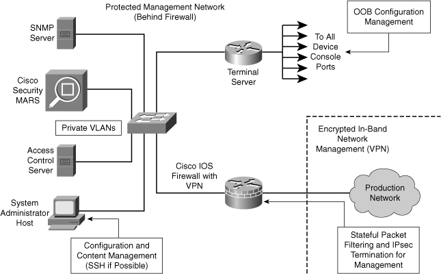
![]() Figure 2-29 shows a management module with two network segments that are separated by a Cisco IOS router that acts as a firewall and a VPN termination device. The segment outside of the firewall connects to all of the devices that require management. The segment inside of the firewall contains the management hosts themselves and the Cisco IOS routers that act as terminal servers.
Figure 2-29 shows a management module with two network segments that are separated by a Cisco IOS router that acts as a firewall and a VPN termination device. The segment outside of the firewall connects to all of the devices that require management. The segment inside of the firewall contains the management hosts themselves and the Cisco IOS routers that act as terminal servers.
![]() The information flow between management hosts and the managed devices can take two paths:
The information flow between management hosts and the managed devices can take two paths:
-
 Out-of-band (OOB): Information flows within a network on which no production traffic resides.
 -
 In-band: Information flows across the enterprise production network, the Internet, or both.
![]() The connection to the production network is only provided for selective Internet access, limited in-band management traffic, and IPsec-protected management traffic from predetermined hosts. In-band management occurs only when a management application does not function OOB, or when the Cisco device being managed does not physically have enough interfaces to support the normal management connection. This latter case employs IPsec tunnels. The Cisco IOS firewall is configured to allow syslog information into the management segment, and, in addition, Telnet, SSH, and SNMP, if these services are first initiated by the inside network.
The connection to the production network is only provided for selective Internet access, limited in-band management traffic, and IPsec-protected management traffic from predetermined hosts. In-band management occurs only when a management application does not function OOB, or when the Cisco device being managed does not physically have enough interfaces to support the normal management connection. This latter case employs IPsec tunnels. The Cisco IOS firewall is configured to allow syslog information into the management segment, and, in addition, Telnet, SSH, and SNMP, if these services are first initiated by the inside network.
![]() Because the management network has administrative access to nearly every area of the network, it can be a very attractive target to hackers. The management module has been built with several technologies designed to mitigate such risks. The first primary threat is a hacker attempting to gain access to the management network itself. You can mitigate this threat only through the effective deployment of security features in the remaining modules in the enterprise. All the remaining threats assume that the primary line of defense has been breached. To mitigate the threat of a compromised device, strong access control is implemented at the firewall, and at every other possible device, to prevent exploitation of the management channel. A compromised management device cannot even communicate with other hosts on the same management subnet because private VLANs (PVLAN) on the management segment switches force all traffic from the management devices directly to the Cisco IOS firewall, where filtering takes place.
Because the management network has administrative access to nearly every area of the network, it can be a very attractive target to hackers. The management module has been built with several technologies designed to mitigate such risks. The first primary threat is a hacker attempting to gain access to the management network itself. You can mitigate this threat only through the effective deployment of security features in the remaining modules in the enterprise. All the remaining threats assume that the primary line of defense has been breached. To mitigate the threat of a compromised device, strong access control is implemented at the firewall, and at every other possible device, to prevent exploitation of the management channel. A compromised management device cannot even communicate with other hosts on the same management subnet because private VLANs (PVLAN) on the management segment switches force all traffic from the management devices directly to the Cisco IOS firewall, where filtering takes place.
![]() Network administrators need to securely manage all devices and hosts in the network. Management includes logging and reporting information flow, including content, configurations, and new software, from the devices to the management hosts.
Network administrators need to securely manage all devices and hosts in the network. Management includes logging and reporting information flow, including content, configurations, and new software, from the devices to the management hosts.
![]() From an architectural perspective, providing OOB management of network systems is the best first step in any management and reporting strategy. Devices should have a direct local connection to such a network where possible, and where this is not possible (because of geographic or system-related issues), the device should connect via a private encrypted tunnel over the production network. Such a tunnel should be preconfigured to permit only the traffic required for management and reporting. The tunnel should also be locked down so that only appropriate hosts can initiate and terminate tunnels.
From an architectural perspective, providing OOB management of network systems is the best first step in any management and reporting strategy. Devices should have a direct local connection to such a network where possible, and where this is not possible (because of geographic or system-related issues), the device should connect via a private encrypted tunnel over the production network. Such a tunnel should be preconfigured to permit only the traffic required for management and reporting. The tunnel should also be locked down so that only appropriate hosts can initiate and terminate tunnels.
![]() OOB management is not always desirable. Often, the decision depends on the type of management applications that you are running and the protocols required. For example, consider a management tool with the goal of determining the reachability of all the devices on the production network. If a critical link failed between two core switches, you would want this management console to alert an administrator. If this management application is configured to use an OOB network, it may never determine that the link has failed, because the OOB network makes all devices appear to be attached to a single OOB management network. With management applications such as these, it is preferable to run the management application in-band. In-band management needs to be configured in a secure manner.
OOB management is not always desirable. Often, the decision depends on the type of management applications that you are running and the protocols required. For example, consider a management tool with the goal of determining the reachability of all the devices on the production network. If a critical link failed between two core switches, you would want this management console to alert an administrator. If this management application is configured to use an OOB network, it may never determine that the link has failed, because the OOB network makes all devices appear to be attached to a single OOB management network. With management applications such as these, it is preferable to run the management application in-band. In-band management needs to be configured in a secure manner.
![]() SNMP management has its own set of security needs. Use SNMPv3 where possible, because SMNPv3 supports authentication and encryption. Keeping SNMP traffic on the management segment allows the traffic to traverse an isolated segment when it pulls management information from devices. To reduce security risks, SNMP management only pulls information from devices rather than being allowed to push changes to the devices. To ensure management information is pulled, each device is configured with a read-only SNMP community string. You can configure an SNMP read-write community string when using an OOB network; however, be aware of the increased security risk of a plaintext string that allows modification of device configurations if an earlier SNMP version is used.
SNMP management has its own set of security needs. Use SNMPv3 where possible, because SMNPv3 supports authentication and encryption. Keeping SNMP traffic on the management segment allows the traffic to traverse an isolated segment when it pulls management information from devices. To reduce security risks, SNMP management only pulls information from devices rather than being allowed to push changes to the devices. To ensure management information is pulled, each device is configured with a read-only SNMP community string. You can configure an SNMP read-write community string when using an OOB network; however, be aware of the increased security risk of a plaintext string that allows modification of device configurations if an earlier SNMP version is used.
Secure Management and Reporting Guidelines
![]() The guidelines for OOB and in-band management of the architecture are as follow:
The guidelines for OOB and in-band management of the architecture are as follow:
-
 Management guidelines
  Keep clocks on hosts and network devices synchronized.
 Record changes and archive configurations.
 -
 OOB management guidelines
  Provide the highest level of security and mitigate the risk of passing unsecure management protocols over the production network.
 -
 Apply only to devices that need to be managed or monitored.
 Use IPsec, SSH, or SSL when possible.
 Decide whether the management channel needs to be open at all times.
![]() As a general rule, OOB management is appropriate for large enterprise networks. In smaller networks, in-band management is recommended as a means of achieving a more cost-effective security deployment. In such architectures, management traffic flows in-band in all cases and is made as secure as possible using tunneling protocols and secure variants to unsecure management protocols; for example, SSH is used whenever possible rather than Telnet.
As a general rule, OOB management is appropriate for large enterprise networks. In smaller networks, in-band management is recommended as a means of achieving a more cost-effective security deployment. In such architectures, management traffic flows in-band in all cases and is made as secure as possible using tunneling protocols and secure variants to unsecure management protocols; for example, SSH is used whenever possible rather than Telnet.
![]() To ensure that log messages are synchronized with one another, clocks on hosts and network devices must be synchronized. For devices that support it, NTP provides a way to ensure that accurate time is kept on all devices.
To ensure that log messages are synchronized with one another, clocks on hosts and network devices must be synchronized. For devices that support it, NTP provides a way to ensure that accurate time is kept on all devices.
![]() NTP is used to synchronize the clocks of various devices across a network. Synchronization of the clocks within a network is critical for digital certificates and for correct interpretation of events within the syslog data.
NTP is used to synchronize the clocks of various devices across a network. Synchronization of the clocks within a network is critical for digital certificates and for correct interpretation of events within the syslog data.
![]() When in-band management of a device is required, consider these questions:
When in-band management of a device is required, consider these questions:
-
 What management protocols does the device support? Devices with IPsec should be managed by simply creating a tunnel from the management network to the device. This setup allows many insecure management protocols to flow over a single encrypted tunnel. When IPsec is not possible because it is not supported on a device, other, less-secure options must be chosen. For configuration of the device, SSH or Secure Sockets Layer (SSL) can often be used rather than Telnet to encrypt any configuration modifications made to a device. These protocols can sometimes also be used to push and pull data to a device instead of unsecure protocols such as TFTP and FTP. Often, however, TFTP is required on Cisco equipment to back up configurations or to update software versions. This fact leads to the second question.
 -
 Does this management channel need to be active at all times? If not, you can place temporary holes in a firewall while the management functions are performed and then later remove them. This process does not scale with large numbers of devices, however, and should be used sparingly, if at all, in enterprise deployments. If the channel needs to be active at all times, such as with SNMP, the third question should be considered.
 -
 Do you really need this management tool? Often, SNMP managers are used on the inside of a network to ease troubleshooting and configuration. However, SNMP should be treated with the utmost care because the underlying protocol has its own set of security vulnerabilities. If SNMP is required, consider providing read-only access to devices via SNMP, and treat the SNMP community string with the same care that you might use for a root password on a critical UNIX host. Know that by introducing SNMP into your production network, you are introducing a potential vulnerability into your environment. Finally, if you do need SNMP, use SNMPv3 authentication and encryption features.
 -
 Is there a change management policy or plan in place? If you are going to adopt new management methodologies, does everyone who needs access have access? Are old tools disabled? These issues should be dealt with in your change management policy.
 Using Syslog Logging for Network Security
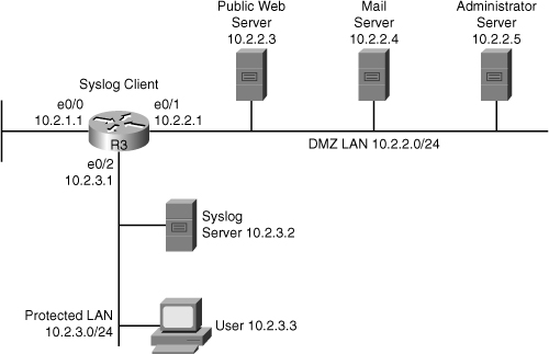
![]() Syslog is the standard for logging system events. As shown in Figure 2-30, syslog implementations contain two types of systems:
Syslog is the standard for logging system events. As shown in Figure 2-30, syslog implementations contain two types of systems:
-
 Syslog servers: These systems are also known as log hosts. These systems accept and process log messages from syslog clients.
 -
 Syslog clients: Syslog clients are routers or other types of Cisco equipment that generate and forward log messages to syslog servers.
| Note |
|
Cisco Security Monitoring, Analysis, and Response System
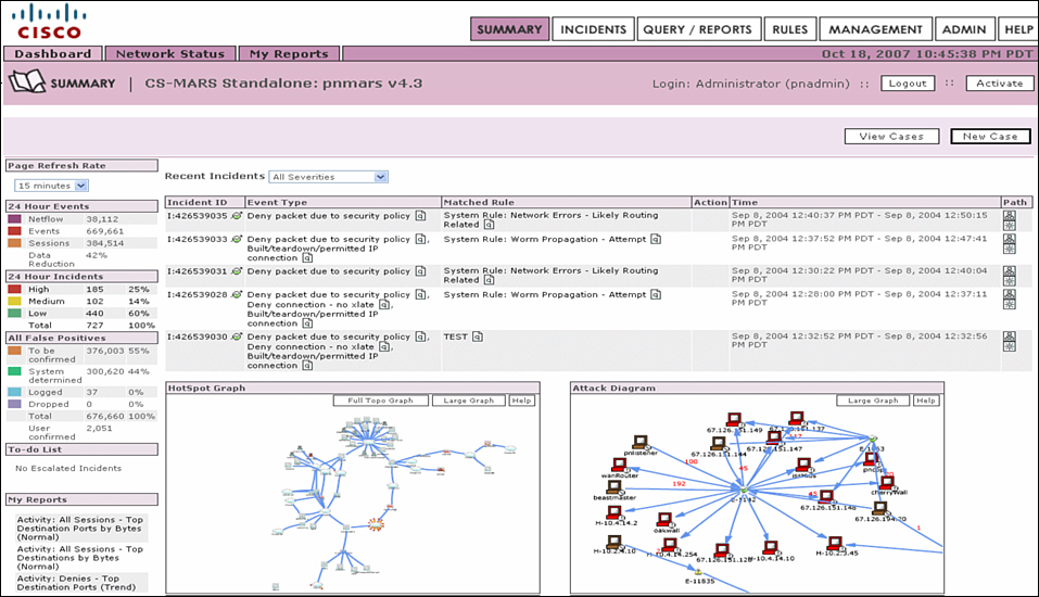
![]() The Cisco Security MARS is a Cisco security appliance that can receive and analyze syslog messages from various networking devices and hosts from Cisco and other vendors. Cisco Security MARS extends the portfolio of security management products for the Cisco Self-Defending Network initiative. Cisco Security MARS is the first purpose-built appliance for real-time security threat mitigation. Figure 2-31 shows the graphical user interface of Cisco Secure MARS.
The Cisco Security MARS is a Cisco security appliance that can receive and analyze syslog messages from various networking devices and hosts from Cisco and other vendors. Cisco Security MARS extends the portfolio of security management products for the Cisco Self-Defending Network initiative. Cisco Security MARS is the first purpose-built appliance for real-time security threat mitigation. Figure 2-31 shows the graphical user interface of Cisco Secure MARS.
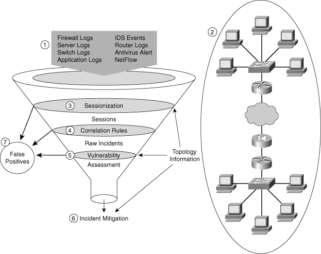
![]() Cisco Security MARS monitors many types of logging and reporting traffic that is available from the security and network products in the enterprise network, as shown in Figure 2-32. Cisco Security MARS combines all this log data into a series of sessions that it then compares to a database of rules. If the rules indicate that there might be a problem, an incident is triggered. By using this method, a network administrator can have the Cisco Security MARS appliance process most of the logging data from network devices and focus human efforts on the potential problems.
Cisco Security MARS monitors many types of logging and reporting traffic that is available from the security and network products in the enterprise network, as shown in Figure 2-32. Cisco Security MARS combines all this log data into a series of sessions that it then compares to a database of rules. If the rules indicate that there might be a problem, an incident is triggered. By using this method, a network administrator can have the Cisco Security MARS appliance process most of the logging data from network devices and focus human efforts on the potential problems.
| Note |
|
Implementing Log Messaging for Security
![]() Implementing a router logging facility is an important part of any network security policy. Cisco routers can log information regarding configuration changes, ACL violations, interface status, and many other types of events. Cisco routers can send log messages to several different facilities. You should configure the router to send log messages to one or more of the following items:
Implementing a router logging facility is an important part of any network security policy. Cisco routers can log information regarding configuration changes, ACL violations, interface status, and many other types of events. Cisco routers can send log messages to several different facilities. You should configure the router to send log messages to one or more of the following items:
-
 Console: Console logging is used when modifying or testing the router while it is connected to the console. Messages sent to the console are not stored by the router and, therefore, are not very valuable as security events.
 -
 Terminal lines: You can configure enabled EXEC sessions to receive log messages on any terminal lines. Similar to console logging, this type of logging is not stored by the router and, therefore, is valuable only to the user on that line.
 -
 Buffered logging: You can direct a router to store log messages in router memory. Buffered logging is a little more useful as a security tool but has the drawback of having events cleared whenever the router is rebooted.
 -
 SNMP traps: Certain router events can be processed by the router SNMP agent and forwarded as SNMP traps to an external SNMP server. SNMP traps are a viable security logging facility but require the configuration and maintenance of an SNMP system.
 -
 Syslog: You can configure Cisco routers to forward log messages to an external syslog service. This service can reside on any number of servers, including Microsoft Windows and UNIX-based systems, or the Cisco Security MARS appliance. Syslog is the most popular message logging facility because this facility provides long-term log storage capabilities and a central location for all router messages.
![]() Cisco router log messages fall into one of eight levels, as shown in Table 2-14. The lower the level number, the higher the severity level, as the log messages in the table denote.
Cisco router log messages fall into one of eight levels, as shown in Table 2-14. The lower the level number, the higher the severity level, as the log messages in the table denote.
|
|
|
|
|---|---|---|
|
|
|
|
|
|
|
|
|
|
|
|
|
|
|
|
|
|
|
|
|
|
|
|
|
|
|
|
|
|
|
|
| Note |
|
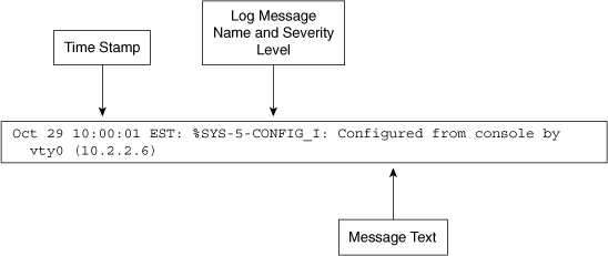
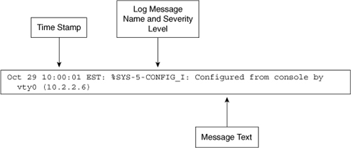
![]() Cisco router log messages contain three main parts:
Cisco router log messages contain three main parts:
-
 Time stamp
 -
 Log message name and severity level
 -
 Message text
![]() Figure 2-33 shows a syslog entry example for a level 5 syslog message, indicating that someone has configured the router using the vty 0 port.
Figure 2-33 shows a syslog entry example for a level 5 syslog message, indicating that someone has configured the router using the vty 0 port.
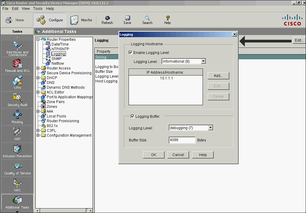
![]() To enable syslog logging on your router using Cisco Router and Security Device Manager (SDM) follow these steps, shown in Figure 2-34:
To enable syslog logging on your router using Cisco Router and Security Device Manager (SDM) follow these steps, shown in Figure 2-34:
|
|
|
|
| |
|
|
|
|
|
|
|
|
|
|
|
|
![]() Example 2-32 shows the resulting CLI commands that Cisco SDM will generate in Figure 2-35. In Example 2-32, the logging buffer is returned to its default value of 4096 bytes.
Example 2-32 shows the resulting CLI commands that Cisco SDM will generate in Figure 2-35. In Example 2-32, the logging buffer is returned to its default value of 4096 bytes.
 Using Logs to Monitor Network Security
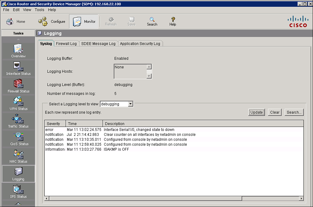
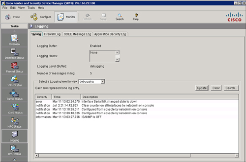
![]() You can use Cisco SDM to monitor logging. Figure 2-35 shows the logging screen that appears when you choose Monitor > Logging.
You can use Cisco SDM to monitor logging. Figure 2-35 shows the logging screen that appears when you choose Monitor > Logging.
![]() From the Syslog tab, you can perform the following functions:
From the Syslog tab, you can perform the following functions:
-
 See the logging hosts to which the router logs messages
 -
 Choose the minimum severity level to view
 -
 Monitor the router syslog messages, update the screen to show the most current log entries, and erase all syslog messages from the router log buffer
 Using SNMP to Manage Network Devices
![]() SNMP was developed to manage nodes, such as servers, workstations, routers, switches, hubs, and security appliances, on an IP network. All versions of SNMP are application layer protocols that facilitate the exchange of management information between network devices. SNMP is part of the TCP/IP protocol suite. SNMP enables network administrators to manage network performance, find and solve network problems, and plan for network growth.
SNMP was developed to manage nodes, such as servers, workstations, routers, switches, hubs, and security appliances, on an IP network. All versions of SNMP are application layer protocols that facilitate the exchange of management information between network devices. SNMP is part of the TCP/IP protocol suite. SNMP enables network administrators to manage network performance, find and solve network problems, and plan for network growth.
![]() SNMP Version 1 (SNMPv1) and SNMP Version 2 (SNMPv2) are based on three concepts:
SNMP Version 1 (SNMPv1) and SNMP Version 2 (SNMPv2) are based on three concepts:
-
 Managers (network management systems [NMS])
 -
 Agents (managed nodes)
 -
 MIBs
MIBs
![]() In any configuration, at least one manager node runs SNMP management software. Network devices that need to be managed, such as switches, routers, servers, and workstations, are equipped with an SMNP agent software module. The agent is responsible for providing access to a local MIB of objects that reflects the resources and activity at its node.
In any configuration, at least one manager node runs SNMP management software. Network devices that need to be managed, such as switches, routers, servers, and workstations, are equipped with an SMNP agent software module. The agent is responsible for providing access to a local MIB of objects that reflects the resources and activity at its node.
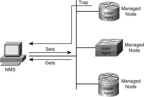
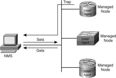
![]() The SNMP manager can retrieve, or “get,” information from the agent, and change, or “set,” information in the agent, as shown in Figure 2-36. Sets can change variables (settings, configuration) in the agent device or initiate actions in devices. A reply to a set indicates the new setting in the device. For example, a set can cause a router to reboot, send a configuration file, or receive a configuration file. SNMP traps enable an agent to notify the management station of significant events by sending an unsolicited SNMP message.
The SNMP manager can retrieve, or “get,” information from the agent, and change, or “set,” information in the agent, as shown in Figure 2-36. Sets can change variables (settings, configuration) in the agent device or initiate actions in devices. A reply to a set indicates the new setting in the device. For example, a set can cause a router to reboot, send a configuration file, or receive a configuration file. SNMP traps enable an agent to notify the management station of significant events by sending an unsolicited SNMP message.
![]() The action of gets and sets are the vulnerabilities that open SNMP to attack.
The action of gets and sets are the vulnerabilities that open SNMP to attack.
![]() SNMPv1 and SNMPv2 use a community string to access router SNMP agents. SNMP community strings act like passwords. An SNMP community string is a text string that can authenticate messages between a management station and an SNMP engine:
SNMPv1 and SNMPv2 use a community string to access router SNMP agents. SNMP community strings act like passwords. An SNMP community string is a text string that can authenticate messages between a management station and an SNMP engine:
-
 If the manager sends one of the correct read-only community strings, it can get information but not set information in an agent.
 -
 If the manager uses one of the correct read-write community strings, it can get or set information in the agent.
![]() In effect, having set access to a router is equivalent to having the enable password of the router.
In effect, having set access to a router is equivalent to having the enable password of the router.
![]() SNMP agents accept commands and requests only from SNMP systems using the correct community string. By default, most SNMP systems use public as a community string. If you configure your router SNMP agent to use this commonly known community string, anyone with an SNMP system is able to read the router MIB. Because router MIB variables can point to things such as routing tables and other security-critical parts of the router configuration, it is extremely important that you create your own custom SNMP community strings.
SNMP agents accept commands and requests only from SNMP systems using the correct community string. By default, most SNMP systems use public as a community string. If you configure your router SNMP agent to use this commonly known community string, anyone with an SNMP system is able to read the router MIB. Because router MIB variables can point to things such as routing tables and other security-critical parts of the router configuration, it is extremely important that you create your own custom SNMP community strings.
SNMPv3 Architecture
![]() In its natural evolution, the current version of SNMPv3 addresses the vulnerabilities of earlier versions by including three important services: authentication, privacy, and access control.
In its natural evolution, the current version of SNMPv3 addresses the vulnerabilities of earlier versions by including three important services: authentication, privacy, and access control.
![]() SNMPv3 is an interoperable standards-based protocol for network management. SNMPv3 uses a combination of authenticating and encrypting packets over the network to provide secure access to devices. SNMPv3 provides the following security features:
SNMPv3 is an interoperable standards-based protocol for network management. SNMPv3 uses a combination of authenticating and encrypting packets over the network to provide secure access to devices. SNMPv3 provides the following security features:
-
 Message integrity: Ensures that a packet has not been tampered with in transit
 -
 Authentication: Determines that the message is from a valid source
 -
 Encryption: Scrambles the contents of a packet to prevent it from being seen by an unauthorized source
![]() SNMP v3 provides for a combination of both, security model and security level, which determine the security mechanism that will be used when handling an SNMP packet.
SNMP v3 provides for a combination of both, security model and security level, which determine the security mechanism that will be used when handling an SNMP packet.
![]() A security model is an authentication strategy that is set up for a user and the group in which the user resides. Currently, Cisco IOS Software supports three security models: SNMPv1, SNMPv2c, and SNMPv3. Meanwhile, a security level is the permitted level of security within a security model. The security level is a type of security algorithm that is performed on each SNMP packet. There are three security levels:
A security model is an authentication strategy that is set up for a user and the group in which the user resides. Currently, Cisco IOS Software supports three security models: SNMPv1, SNMPv2c, and SNMPv3. Meanwhile, a security level is the permitted level of security within a security model. The security level is a type of security algorithm that is performed on each SNMP packet. There are three security levels:
-
 noAuth: This security level authenticates a packet by a string match of the username or community string.
 -
 auth: This level authenticates a packet by using either the Hashed Message Authentication Code (HMAC) with Message Digest 5 (MD5) method or Secure Hash Algorithms (SHA) method. This method is described in RFC 2104, HMAC: Keyed-Hashing for Message Authentication.
 -
 Priv: This level authenticates a packet by using either the HMAC MD5 or HMAC SHA algorithms and encrypts the packet using the Data Encryption Standard (DES), Triple DES (3DES), or Advanced Encryption Standard (AES) algorithms.
| Note |
|
![]() Table 2-15 identifies what the combinations of security models and levels mean.
Table 2-15 identifies what the combinations of security models and levels mean.
|
|
|
|
| |
|---|---|---|---|---|
|
|
|
|
|
|
|
|
|
|
|
|
|
|
|
|
|
|
|
|
|
|
|
|
|
|
|
|
|
|
Enabling SNMP Options Using Cisco SDM
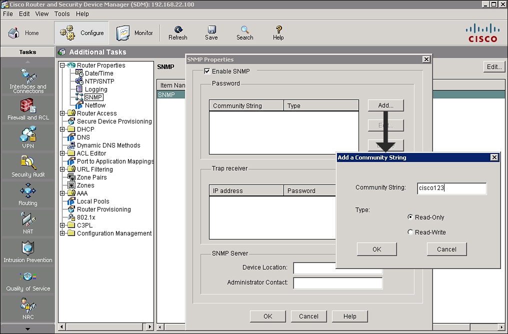
![]() You can use Cisco SDM to enable SNMP, set SNMP community strings, and enter SNMP trap receiver information, as shown in Figure 2-37.
You can use Cisco SDM to enable SNMP, set SNMP community strings, and enter SNMP trap receiver information, as shown in Figure 2-37.
| Note |
|
![]() Follow these steps to enable SNMP options using Cisco SDM:
Follow these steps to enable SNMP options using Cisco SDM:
|
|
|
|
|
|
|
|
|
Viewing and Managing SNMP Community Strings Using Cisco SDM
![]() SNMP community strings are like passwords that allow access to the information in MIBs. MIBs store data about router operation and are meant to be available to authenticated remote users. There are two types of community strings:
SNMP community strings are like passwords that allow access to the information in MIBs. MIBs store data about router operation and are meant to be available to authenticated remote users. There are two types of community strings:
-
 Read-only community strings: This type of community string provides read-only access to all objects in the MIB except the community strings.
 -
 Read-write community strings: This type of community string provides read-write access to all objects in the MIB except the community strings.
![]() Follow these steps to use Cisco SDM to view and manage community strings:
Follow these steps to use Cisco SDM to view and manage community strings:
|
|
|
|
|
|
Configuring Trap Receivers
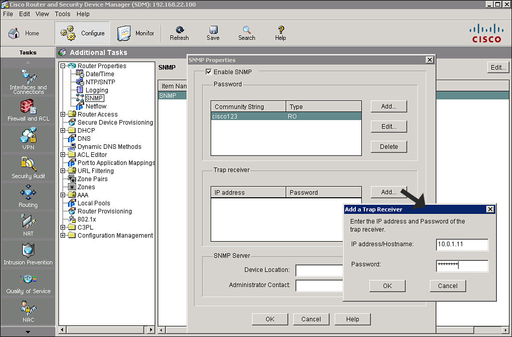
![]() You can also configure the devices to which a router sends traps. These devices are referred to as trap receivers. Follow these steps, shown in Figure 2-38, to use Cisco SDM to add, edit, or delete a trap receiver:
You can also configure the devices to which a router sends traps. These devices are referred to as trap receivers. Follow these steps, shown in Figure 2-38, to use Cisco SDM to add, edit, or delete a trap receiver:
![]() Still on Figure 2-38, in the SNMP Properties window you will also notice the SNMP Server Device Location field and the SNMP Server Administrator Contact field. Both of these fields are text fields that you can use to enter descriptive information about the SNMP server location and the contact information for a person managing the SNMP server. These fields are not required and do not affect the operation of the router.
Still on Figure 2-38, in the SNMP Properties window you will also notice the SNMP Server Device Location field and the SNMP Server Administrator Contact field. Both of these fields are text fields that you can use to enter descriptive information about the SNMP server location and the contact information for a person managing the SNMP server. These fields are not required and do not affect the operation of the router.
![]() The resulting CLI command that Cisco SDM will generate based on the example in Figure 2-37 and 2-38 is snmp-server community cisco123 RO and snmp-server host 10.0.1.11 trap cisco123.
The resulting CLI command that Cisco SDM will generate based on the example in Figure 2-37 and 2-38 is snmp-server community cisco123 RO and snmp-server host 10.0.1.11 trap cisco123.
 Configuring an SSH Daemon for Secure Management and Reporting
![]() The SSH daemon is a feature that enables an SSH client to make a secure, encrypted connection to a Cisco router. This connection provides functionality similar to that of an inbound Telnet connection, but it also provides strong encryption to be used with local authentication. The SSH daemon in Cisco IOS Software works with publicly and commercially available SSH clients. This feature is disabled if the router is not using an IPsec DES or 3DES Cisco IOS Software image.
The SSH daemon is a feature that enables an SSH client to make a secure, encrypted connection to a Cisco router. This connection provides functionality similar to that of an inbound Telnet connection, but it also provides strong encryption to be used with local authentication. The SSH daemon in Cisco IOS Software works with publicly and commercially available SSH clients. This feature is disabled if the router is not using an IPsec DES or 3DES Cisco IOS Software image.
![]() Whenever possible, you should use SSH rather than Telnet to manage your Cisco routers. Cisco IOS Software Release 12.1(1)T and later support SSHv1, and Cisco IOS Release 12.3(4)T and later support both SSHv1 and SSHv2. Cisco routers configured for SSH act as SSH daemons. You must provide an SSH client, such as PuTTY, OpenSSH, or Tera Term, for the administrator workstation that you want to use to configure and manage routers using SSH.
Whenever possible, you should use SSH rather than Telnet to manage your Cisco routers. Cisco IOS Software Release 12.1(1)T and later support SSHv1, and Cisco IOS Release 12.3(4)T and later support both SSHv1 and SSHv2. Cisco routers configured for SSH act as SSH daemons. You must provide an SSH client, such as PuTTY, OpenSSH, or Tera Term, for the administrator workstation that you want to use to configure and manage routers using SSH.
| Tip |
|
![]() Complete the following tasks before you configure your routers for SSH daemon operations:
Complete the following tasks before you configure your routers for SSH daemon operations:
-
 Ensure that the target routers are running an IOS image which supports SSH, such as Release 12.1(1)T image or later with the IPsec feature set. For more information about which IOS supports SSH, refer to the Software Advisor at Cisco.com for a complete list.
 -
 Ensure that the target routers are configured for local authentication, or for AAA services for username or password authentication, or both.
 -
 Ensure that each of the target routers has a unique hostname.
 -
 Ensure that each of the target routers is using the correct domain name of your network.
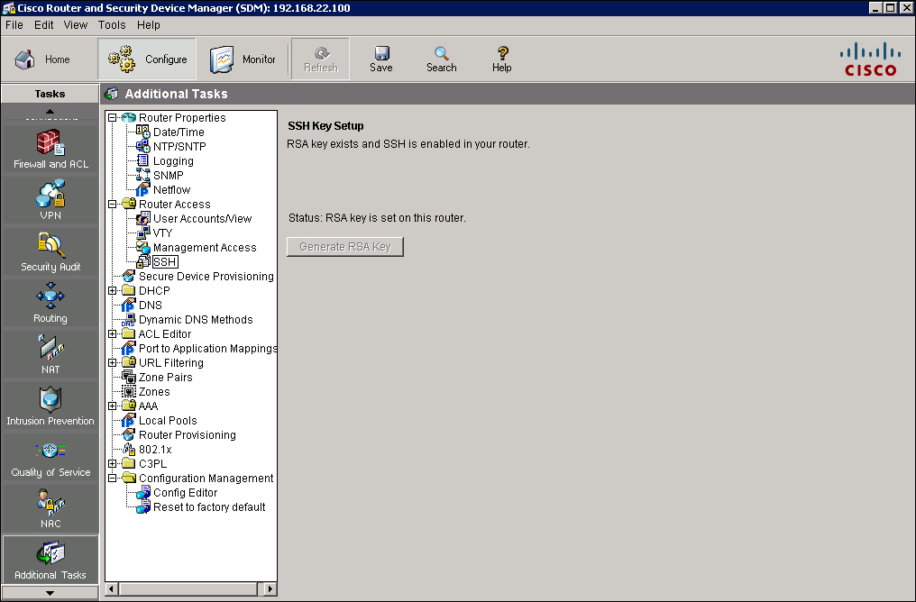
![]() You can use Cisco SDM to configure an SSH daemon on a router, as shown in Figure 2-39.
You can use Cisco SDM to configure an SSH daemon on a router, as shown in Figure 2-39.
![]() To see the current SSH key settings, choose Configure > Additional Tasks > Router Access > SSH. The SSH key settings have two status options:
To see the current SSH key settings, choose Configure > Additional Tasks > Router Access > SSH. The SSH key settings have two status options:
-
 RSA key is not set on this router: This notice appears if there is no cryptographic key configured for the device. If there is no key configured, you can enter a modulus size and generate a key.
 -
 RSA key is set on this router: This option appears if a cryptographic key has been generated, in which case SSH is enabled on this router.
| Note |
|
![]() To configure a cryptographic key if one is not set, click the Generate RSA Key button. The Key Modulus Size dialog box appears. Enter the modulus size that you want to give the key. If you want a modulus value between 512 and 1024, enter an integer value that is a multiple of 64. If you want a value higher than 1024, you can enter 1536 or 2048. If you enter a value greater than 512, key generation can take a minute or longer.
To configure a cryptographic key if one is not set, click the Generate RSA Key button. The Key Modulus Size dialog box appears. Enter the modulus size that you want to give the key. If you want a modulus value between 512 and 1024, enter an integer value that is a multiple of 64. If you want a value higher than 1024, you can enter 1536 or 2048. If you enter a value greater than 512, key generation can take a minute or longer.
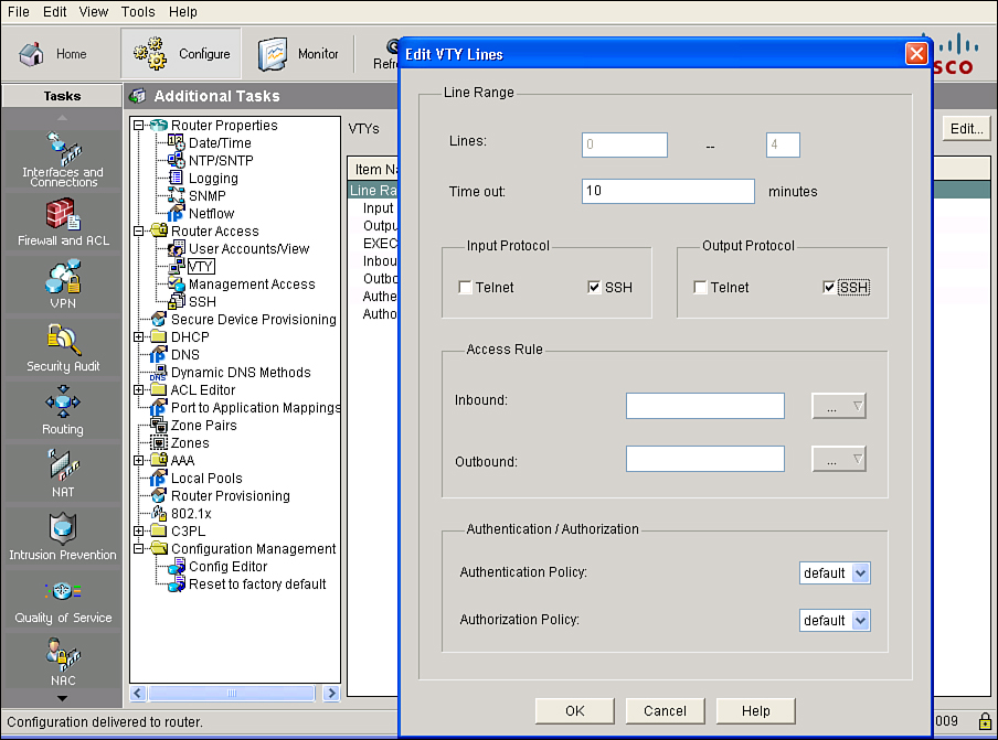
![]() After you enable SSH on the router, you must configure the vty lines to support SSH. To use Cisco SDM to configure SSH on the vty lines, choose Configure > Additional Tasks > Router Access > VTY, as shown in Figure 2-40. The VTY Lines window displays the vty settings on your router. The Property column contains the configured line ranges and the configurable properties for each range. The settings for these properties are contained in the Value column.
After you enable SSH on the router, you must configure the vty lines to support SSH. To use Cisco SDM to configure SSH on the vty lines, choose Configure > Additional Tasks > Router Access > VTY, as shown in Figure 2-40. The VTY Lines window displays the vty settings on your router. The Property column contains the configured line ranges and the configurable properties for each range. The settings for these properties are contained in the Value column.
![]() The window shows the following router vty settings:
The window shows the following router vty settings:
-
 Line Range: This setting displays the range of vty connections to which the rest of the settings in the row apply.
 -
 Input Protocols Allowed: This setting displays the protocols that are configured for input, which can be Telnet, SSH, or both Telnet and SSH.
 -
 Output Protocols Allowed: This setting displays the protocols that are configured for output, which can be Telnet, SSH, or both Telnet and SSH.
 -
 EXEC Timeout: This setting displays the number of seconds of inactivity after which a session is terminated.
 -
 Inbound Access-Class: This setting displays the name or number of the ACL that is applied to the inbound direction of the line range.
 -
 Outbound Access-Class: This setting displays the name or number of the ACL that is applied to the outbound direction of the line range.
 -
 ACL: If configured, this setting shows the ACL that is associated with the vty connections.
 -
 Authentication Policy: This setting displays the AAA authentication policy associated with this vty line. This field is not visible if AAA is not configured on the router.
 -
 Authorization Policy: This setting displays the AAA authorization policy associated with this vty line. This field is not visible if AAA is not configured on the router.
![]() To change these settings, click the Edit button. The Edit VTY Lines window appears. From this window you can enable SSH on the vty lines by checking the SSH check box in the Input Protocol section or the Output Protocol section or both.
To change these settings, click the Edit button. The Edit VTY Lines window appears. From this window you can enable SSH on the vty lines by checking the SSH check box in the Input Protocol section or the Output Protocol section or both.
![]() Follow these steps to configure your Cisco router to support an SSH daemon using the CLI:
Follow these steps to configure your Cisco router to support an SSH daemon using the CLI:
![]() The SSH protocol is automatically enabled when you generate the SSH (RSA) keys. Once the keys are created, you can access the router SSH daemon using your SSH client software.
The SSH protocol is automatically enabled when you generate the SSH (RSA) keys. Once the keys are created, you can access the router SSH daemon using your SSH client software.
| Tip |
|
![]() The procedure for connecting to a Cisco router SSH daemon varies depending on the SSH client application that you use. Generally, the SSH client passes your username to the router SSH daemon. The router SSH daemon prompts you for the correct password. After the password has been verified, you can configure and manage the router as if you were a standard vty user.
The procedure for connecting to a Cisco router SSH daemon varies depending on the SSH client application that you use. Generally, the SSH client passes your username to the router SSH daemon. The router SSH daemon prompts you for the correct password. After the password has been verified, you can configure and manage the router as if you were a standard vty user.
 Enabling Time Features
![]() Because many things that are involved in the security of your network depend on an accurate date and time stamp, such as security certificates, it is important that the router maintains the correct time.
Because many things that are involved in the security of your network depend on an accurate date and time stamp, such as security certificates, it is important that the router maintains the correct time.
![]() You can use Cisco SDM to configure the date and time settings of the router in three ways:
You can use Cisco SDM to configure the date and time settings of the router in three ways:
Synchronizing Cisco SDM with the Local PC Clock
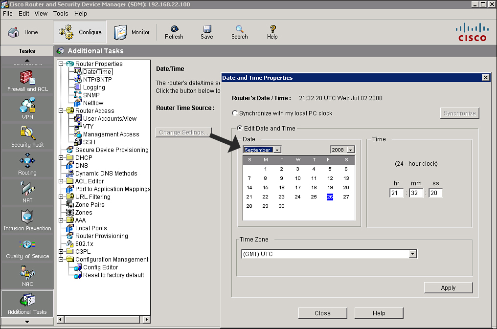
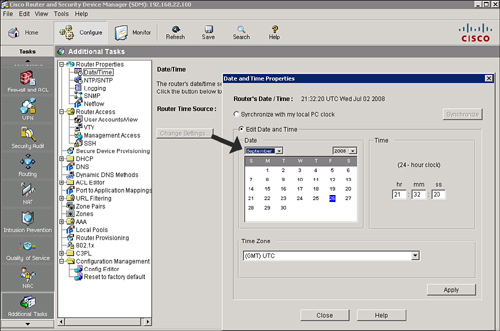
![]() Follow these steps to synchronize the router time settings with the PC that is running Cisco SDM, as shown in Figure 2-41:
Follow these steps to synchronize the router time settings with the PC that is running Cisco SDM, as shown in Figure 2-41:
|
|
|
|
|
|
|
|
|
| Note |
|
Manually Editing the Date and Time
![]() Follow these steps to use Cisco SDM to manually configure the time settings of the router (referring to Figure 2-41):
Follow these steps to use Cisco SDM to manually configure the time settings of the router (referring to Figure 2-41):
|
|
|
|
|
|
|
|
|
Network Time Protocol
![]() NTP is a secure method to synchronize date and time settings for devices on the network. NTP uses UDP port 123 and is documented in RFC 1305. Simple Network Time Protocol (SNTP) is a simpler, less-secure version of NTP.
NTP is a secure method to synchronize date and time settings for devices on the network. NTP uses UDP port 123 and is documented in RFC 1305. Simple Network Time Protocol (SNTP) is a simpler, less-secure version of NTP.
![]() When you implement NTP in your network, you can set up your own master clock, or you can use a publicly available NTP server on the Internet. If you implement your own master clock, you should synchronize the private network to Coordinated universal time (UTC) via satellite or radio.
When you implement NTP in your network, you can set up your own master clock, or you can use a publicly available NTP server on the Internet. If you implement your own master clock, you should synchronize the private network to Coordinated universal time (UTC) via satellite or radio.
![]() You need to be careful when you implement NTP. An attacker can launch a denial-of-service (DoS) attack by sending bogus NTP data across the Internet to your network in an attempt to change the clocks on network devices, possibly causing digital certificates to become invalid. Further, an attacker could attempt to confuse a network administrator during an attack by disrupting the clocks on network devices. This scenario would make it difficult for the network administrator to determine the order of syslog events on multiple devices.
You need to be careful when you implement NTP. An attacker can launch a denial-of-service (DoS) attack by sending bogus NTP data across the Internet to your network in an attempt to change the clocks on network devices, possibly causing digital certificates to become invalid. Further, an attacker could attempt to confuse a network administrator during an attack by disrupting the clocks on network devices. This scenario would make it difficult for the network administrator to determine the order of syslog events on multiple devices.
![]() NTP Version 3 (NTPv3) and later support a cryptographic authentication mechanism between NTP peers. You can use this authentication mechanism, in addition to ACLs that specify which network devices are allowed to synchronize with other network devices, to help mitigate such an attack.
NTP Version 3 (NTPv3) and later support a cryptographic authentication mechanism between NTP peers. You can use this authentication mechanism, in addition to ACLs that specify which network devices are allowed to synchronize with other network devices, to help mitigate such an attack.
![]() You should weigh the benefits of pulling the clock time from the Internet against the possible risk of doing so and allowing unsecured packets through the firewall. Many NTP servers on the Internet do not require any authentication of peers. Therefore, the network administrator must trust that the clock itself is reliable, valid, and secure.
You should weigh the benefits of pulling the clock time from the Internet against the possible risk of doing so and allowing unsecured packets through the firewall. Many NTP servers on the Internet do not require any authentication of peers. Therefore, the network administrator must trust that the clock itself is reliable, valid, and secure.
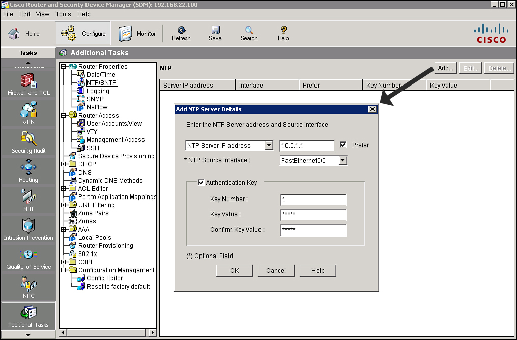
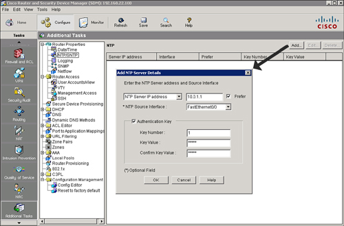
![]() NTP allows routers on your network to synchronize their time settings with an NTP server. A group of NTP clients that obtain time and date information from a single source will have more consistent time settings. Cisco SDM allows you to view the NTP server information that has been configured, add new information, and edit or delete existing information, as shown in Figure 2-42.
NTP allows routers on your network to synchronize their time settings with an NTP server. A group of NTP clients that obtain time and date information from a single source will have more consistent time settings. Cisco SDM allows you to view the NTP server information that has been configured, add new information, and edit or delete existing information, as shown in Figure 2-42.
![]() Follow these steps to add an NTP server using Cisco SDM:
Follow these steps to add an NTP server using Cisco SDM:
|
|
| |||
|
|
| |||
|
|
| |||
|
|
| |||
|
|
| |||
|
|
| |||
|
|
|
![]() The resulting CLI command that Cisco SDM will generate based on the example in Figure 2-43 is ntp server 10.1.1.1 key cisco source fastethernet0/0 prefer.
The resulting CLI command that Cisco SDM will generate based on the example in Figure 2-43 is ntp server 10.1.1.1 key cisco source fastethernet0/0 prefer.
| Note |
|

1 comments
nice work
Post a Comment