Private VLANs
![]() In some situations, you need to prevent Layer 2 connectivity between end devices on a switch in the same VLAN without placing the devices in different IP subnets. This setup prevents IP address wasting. Private VLANs enable the isolation at Layer 2 of devices in the same IP subnet. You can restrict some ports on the switch to reach only specific ports that have a default gateway or backup server attached. With this setting, devices can belong to the same VLAN but still be prevented from communicating with one another. Private VLANs are heavily deployed in the ISP environment—especially the web hosting environment. The following topics related to Private VLANs are discussed in the next section:
In some situations, you need to prevent Layer 2 connectivity between end devices on a switch in the same VLAN without placing the devices in different IP subnets. This setup prevents IP address wasting. Private VLANs enable the isolation at Layer 2 of devices in the same IP subnet. You can restrict some ports on the switch to reach only specific ports that have a default gateway or backup server attached. With this setting, devices can belong to the same VLAN but still be prevented from communicating with one another. Private VLANs are heavily deployed in the ISP environment—especially the web hosting environment. The following topics related to Private VLANs are discussed in the next section:
-
 Given an enterprise VLAN network design that contains Private VLANs, create an implementation and verification plan; then successfully execute that plan.
 Private VLANs Overview
![]() Service providers often have devices from multiple clients, in addition to their own servers, on a single Demilitarized Zone (DMZ) segment or VLAN. As security issues proliferate, it becomes necessary to provide traffic isolation between devices, even though they might exist on the same Layer 3 segment and VLAN. Most Cisco IOS-based switches implement Private VLANs to keep some switch ports shared and some switch ports isolated, although all ports exist on the same VLAN.
Service providers often have devices from multiple clients, in addition to their own servers, on a single Demilitarized Zone (DMZ) segment or VLAN. As security issues proliferate, it becomes necessary to provide traffic isolation between devices, even though they might exist on the same Layer 3 segment and VLAN. Most Cisco IOS-based switches implement Private VLANs to keep some switch ports shared and some switch ports isolated, although all ports exist on the same VLAN.
![]() The traditional solution to address these Internet service provider (ISP) requirements is to provide one VLAN per customer, with each VLAN having its own IP subnet. A Layer 3 device then provides interconnectivity between VLANs and Internet destinations.
The traditional solution to address these Internet service provider (ISP) requirements is to provide one VLAN per customer, with each VLAN having its own IP subnet. A Layer 3 device then provides interconnectivity between VLANs and Internet destinations.
![]() The following are the challenges with this traditional solution:
The following are the challenges with this traditional solution:
-
 Supporting a separate VLAN per customer can require a high number of Layer 3 interfaces on service provider network devices.
 -
 Spanning tree becomes more complicated with many VLAN iterations.
 -
 Network address space must be divided into many subnets, which wastes space and increases management complexity.
 -
 Multiple ACL applications are required to maintain security on multiple VLANs, resulting in increased management complexity.
Private VLANs and Port Types
![]() A port in a Private VLAN can be one of the following three types:
A port in a Private VLAN can be one of the following three types:
-
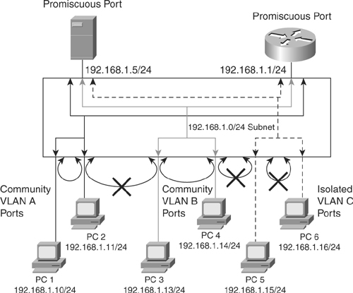
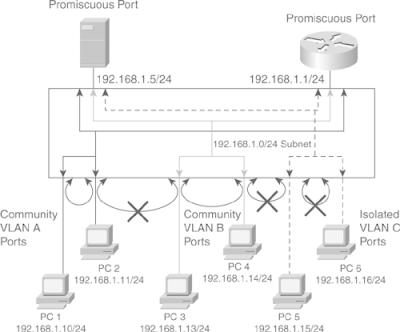
 Isolated: An isolated port has complete Layer 2 separation from other ports within the same Private VLAN, except for the promiscuous ports. Private VLANs block all traffic to isolated ports, except the traffic from promiscuous ports. Traffic received from an isolated port is forwarded to only promiscuous ports. As shown in Figure 2-15, PC 5 and PC 6 belong to same isolated Private VLAN, but they cannot communicate with each other—only with promiscuous.
 -
 Promiscuous: A promiscuous port can communicate with all ports within the Private VLAN, including the community and isolated ports. A promiscuous port is only part of one primary VLAN, but each promiscuous port can map to more than one secondary Private VLAN. Promiscuous ports are generally router ports, backup or shared servers, or VLAN interfaces. As shown in Figure 2-15, the router port and the shared server port is the one that needs to communicate to everyone.
 -
 Community: Community ports communicate among themselves and with their promiscuous ports. These interfaces are isolated at Layer 2 from all other interfaces in other communities, or in isolated ports within their Private VLAN. As shown in Figure 2-15, PC1 and PC2’s ports belong to the community Private VLAN A and PC3, and PC4 belongs to the community Private VLAN B. PC 1 and PC2 can communicate with each other and the promiscuous port but not with PC 3 and PC4, which are part of a different community.
![]() Private VLAN ports are associated with a set of supporting VLANs that create the Private VLAN structure. A Private VLAN uses VLANs in the following ways:
Private VLAN ports are associated with a set of supporting VLANs that create the Private VLAN structure. A Private VLAN uses VLANs in the following ways:
-
 A primary Private VLAN: The high-level VLAN of the Private VLAN. A primary Private VLAN can be composed of many secondary Private VLANs with the secondary Private VLANs belonging to the same subnet of the primary Private VLAN. It carries traffic from promiscuous ports to isolated, community, and other promiscuous ports in the same primary Private VLAN.
 -
 A secondary Private VLAN: Every secondary Private VLAN is a child to a primary Private VLAN and is mapped to one primary Private VLAN. End devices are attached to secondary Private VLANs.
![]() The following are the two types of secondary Private VLANs:
The following are the two types of secondary Private VLANs:
-
 Community Private VLANs: Ports that belong to the community Private VLAN can communicate with the other ports in the same community and promiscuous ports of the Private VLAN, as shown in Figure 2-15, where PC 1 and PC 2, which belong to community Private VLAN A, can communicate with each other but (as indicated by the X) not with PC 3 and PC 4, which belong to community Private VLAN B.
 -
 Isolated Private VLANs: Ports that belong to an isolated Private VLAN can communicate only with promiscuous ports. Isolated ports cannot communicate with other ports in the same isolated Private VLAN, as shown in Figure 2-15, where PC 5 and PC 6, although in the same isolated Private VLAN, cannot communicate with each other but can communicate with the promiscuous ports. Each Private VLAN has only one isolated Private VLAN.
| Note |
|
![]() Private VLAN span across multiple switches by trunking the primary, isolated, and community VLANs to other devices that support Private VLAN.
Private VLAN span across multiple switches by trunking the primary, isolated, and community VLANs to other devices that support Private VLAN.
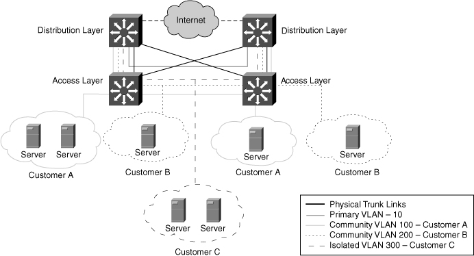
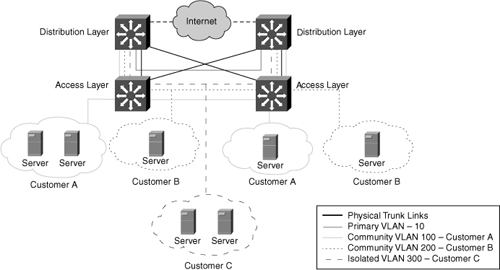
![]() Figure 2-16 illustrates an example of implementing Private VLANs in a service-provider environment. Here, a service provider has three customers under one primary Private VLAN. Customer A belongs to community Private VLAN 100, Customer B belongs to community Private VLAN 200, and Customer C belongs to isolated Private VLAN 300. Despite belonging to the same subnet, Customer A’s, Customer B’s, and Customer C’s network devices cannot communicate with one another. All devices that reside in Customer A’s community Private VLANs can communicate with one another even though the devices are spread across multiple switches. In addition, all devices that reside in Customer B’s community Private VLANs can communicate with one another. However, devices in Customer C’s isolated Private VLAN cannot communicate with one another.
Figure 2-16 illustrates an example of implementing Private VLANs in a service-provider environment. Here, a service provider has three customers under one primary Private VLAN. Customer A belongs to community Private VLAN 100, Customer B belongs to community Private VLAN 200, and Customer C belongs to isolated Private VLAN 300. Despite belonging to the same subnet, Customer A’s, Customer B’s, and Customer C’s network devices cannot communicate with one another. All devices that reside in Customer A’s community Private VLANs can communicate with one another even though the devices are spread across multiple switches. In addition, all devices that reside in Customer B’s community Private VLANs can communicate with one another. However, devices in Customer C’s isolated Private VLAN cannot communicate with one another.
 Private VLAN Configuration
![]() To configure a Private VLAN, follow these steps:
To configure a Private VLAN, follow these steps:
|
|
|
|
|
|
|
|
|
|
|
|
|
| |
|
|
|
|
|
|
|
|
|
Configuring Private VLANs in Cisco IOS
![]() To configure Private VLANs in Cisco IOS, perform the following steps:
To configure Private VLANs in Cisco IOS, perform the following steps:
| Note |
|
 Verifying Private VLAN
![]() Always verify the configuration. Following are some of the commands commonly used to verify Private VLAN configuration:
Always verify the configuration. Following are some of the commands commonly used to verify Private VLAN configuration:
-
 show interface type slot/port switchport
 -
 show vlan private-vlan
![]() Example 2-16 illustrates the commands used to verify the configuration of Private VLANs in Cisco IOS. The interface switchport commands are usually good for verifying the interface config and mode of the port, as shown in Example 2-16.
Example 2-16 illustrates the commands used to verify the configuration of Private VLANs in Cisco IOS. The interface switchport commands are usually good for verifying the interface config and mode of the port, as shown in Example 2-16.
Switch# show vlan private-vlan
Primary Secondary Type Interfaces
------- --------- ----------------- ------------------------------------------
100 200 community
100 300 isolated

Switch# show interfaces FastEthernet 5/2 switchport
Name: Fa5/2
Switchport: Enabled
Administrative Mode: private-vlan host
Operational Mode: down
Administrative Trunking Encapsulation: negotiate
Negotiation of Trunking: On
Access Mode VLAN: 1 (default)
Trunking Native Mode VLAN: 1 (default)
Administrative private-vlan host-association: 100 (VLAN0200) 300 (VLAN0300)
Administrative private-vlan mapping: none
Operational private-vlan: none
Trunking VLANs Enabled: ALL
Pruning VLANs Enabled: 2-1001
Capture Mode Disabled
 Private VLAN Configuration Example
![]() This subsection provides examples to configure Private VLANs in campus networks. It discusses how to configure on a single switch and then how to configure across two switches.
This subsection provides examples to configure Private VLANs in campus networks. It discusses how to configure on a single switch and then how to configure across two switches.
Single Switch Private Configuration
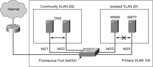
![]() Figure 2-17 is the basis for this example. A corporate DMZ contains two DNS servers, one web server and one SMTP server. All servers and their connecting router are in the same subnet. DNS servers are redundant copies, so they need to communicate with each other to update their entries. In addition to that, they also need to communicate with the Internet. The Web Server and the SMTP server need to communicate with the Internet, but for security purposes, the SMTP server should not be reachable from the Web or the DNS servers. The web server needs to be accessible from the Internet but not from the SMTP server.
Figure 2-17 is the basis for this example. A corporate DMZ contains two DNS servers, one web server and one SMTP server. All servers and their connecting router are in the same subnet. DNS servers are redundant copies, so they need to communicate with each other to update their entries. In addition to that, they also need to communicate with the Internet. The Web Server and the SMTP server need to communicate with the Internet, but for security purposes, the SMTP server should not be reachable from the Web or the DNS servers. The web server needs to be accessible from the Internet but not from the SMTP server.
![]() Network designers can use this configuration either using access control lists, or more simply with Private VLANs. The port to the Internet would be set to promiscuous. A Community VLAN would be created to host both DNS servers, and an isolated VLAN would be created to host the Web and the SMTP servers.
Network designers can use this configuration either using access control lists, or more simply with Private VLANs. The port to the Internet would be set to promiscuous. A Community VLAN would be created to host both DNS servers, and an isolated VLAN would be created to host the Web and the SMTP servers.
![]() Example 2-17 illustrates the configuration of Private VLAN in detail. When the switch is set to VTP transparent mode, the first task is to create the VLANs. Notice that in this configuration the primary VLAN 100 is associated to both the isolated 201 and the community 202.
Example 2-17 illustrates the configuration of Private VLAN in detail. When the switch is set to VTP transparent mode, the first task is to create the VLANs. Notice that in this configuration the primary VLAN 100 is associated to both the isolated 201 and the community 202.
sw(config)# vtp transparent
sw(config)# vlan 201
sw(config-vlan)# private-vlan isolated
sw(config)# vlan 202
sw(config-vlan)# private-vlan community
sw(config-vlan)# vlan 100
sw(config-vlan)# private-vlan primary
sw(config-vlan)# private-vlan association 201,202
sw(config-vllan)# interface fastethernet 0/24
sw(config-if)# switchport mode private-vlan promiscuous
sw(config-if)# switchport private-vlan mapping 100 201,202
sw(config-if)# interface range fastethernet 0/1 - 2
sw(config-if)# switchport mode private-vlan host
sw2(config-if)# switchport private-vlan host-association 100 202
sw(config-if)# interface range fastethernet 0/3 - 4
sw(config-if)# switchport mode private-vlan host
sw2(config-if)# switchport private-vlan host-association 100 201
![]() When the Private VLANs is defined, configure each port to associate to a private VLAN mode. Interface fastethernet 0/1 and fastethernet 0/2 are DNS ports, so associate Private VLAN 100 to 202. Interface fastethernet 0/3 and fastethernet 0/4 are WWW and SMTP servers, so associate Private VLAN 100 to 201. Private VLANs 201 and 202 are mapped to the promiscuous port as a result of being associated with primary Private VLAN 100. Traffic can flow to and from Private VLAN 201 and 202 and to and from the promiscuous port that is a router port on interface 0/24. Keep in mind that all devices in Private VLAN 201, Private VLAN 202, and on the promiscuous port are in the same subnet.
When the Private VLANs is defined, configure each port to associate to a private VLAN mode. Interface fastethernet 0/1 and fastethernet 0/2 are DNS ports, so associate Private VLAN 100 to 202. Interface fastethernet 0/3 and fastethernet 0/4 are WWW and SMTP servers, so associate Private VLAN 100 to 201. Private VLANs 201 and 202 are mapped to the promiscuous port as a result of being associated with primary Private VLAN 100. Traffic can flow to and from Private VLAN 201 and 202 and to and from the promiscuous port that is a router port on interface 0/24. Keep in mind that all devices in Private VLAN 201, Private VLAN 202, and on the promiscuous port are in the same subnet.
Private VLAN Configuration Across Switches
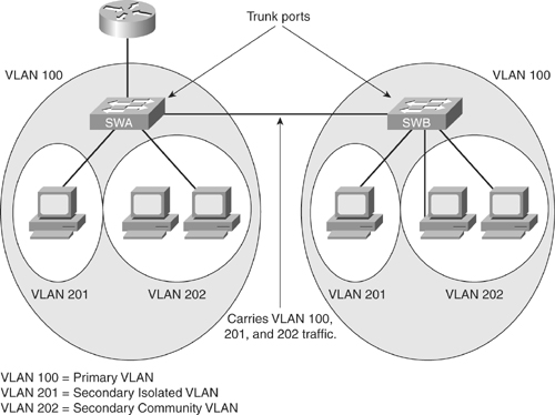
![]() As with regular VLANs, Private VLANs can span multiple switches. A trunk port carries the primary VLAN and secondary VLANs to a neighboring switch just like any other VLAN. A feature of Private VLANs across multiple switches is that traffic from an isolated port in one switch does not reach an isolated port on another switch. Configure Private VLANs on all switches on the path, which includes devices that have no Private VLAN ports to maintain the security of your Private VLAN configuration, and avoid using other VLANs configured as Private VLANs. As illustrated in Figure 2-18, the switches SWA and SWA have the same Private VLANs spread on two different switches and are connected through the trunk link.
As with regular VLANs, Private VLANs can span multiple switches. A trunk port carries the primary VLAN and secondary VLANs to a neighboring switch just like any other VLAN. A feature of Private VLANs across multiple switches is that traffic from an isolated port in one switch does not reach an isolated port on another switch. Configure Private VLANs on all switches on the path, which includes devices that have no Private VLAN ports to maintain the security of your Private VLAN configuration, and avoid using other VLANs configured as Private VLANs. As illustrated in Figure 2-18, the switches SWA and SWA have the same Private VLANs spread on two different switches and are connected through the trunk link.
![]() Because VTP does not support Private VLANs, configure the Private VLANs manually on all switches in the Layer 2 network. If the primary and secondary VLAN associations are configured in some switches but not all in the path, the Private VLAN databases and mapping will be different in each switch in the path.. This situation can result in unnecessary flooding of Private VLAN traffic on those switches.
Because VTP does not support Private VLANs, configure the Private VLANs manually on all switches in the Layer 2 network. If the primary and secondary VLAN associations are configured in some switches but not all in the path, the Private VLAN databases and mapping will be different in each switch in the path.. This situation can result in unnecessary flooding of Private VLAN traffic on those switches.
![]() To trunk Private VLANs on a host port or a port that is supposed to carry multiple secondary VLANs, the Private VLAN trunk feature is also available. A Private VLAN trunk port can carry multiple secondary and non-Private VLANs. Packets are received and transmitted with secondary or regular VLAN tags on the Private VLAN trunk ports.
To trunk Private VLANs on a host port or a port that is supposed to carry multiple secondary VLANs, the Private VLAN trunk feature is also available. A Private VLAN trunk port can carry multiple secondary and non-Private VLANs. Packets are received and transmitted with secondary or regular VLAN tags on the Private VLAN trunk ports.
![]() The Private VLAN host trunk feature is supported only with 801.1Q encapsulation. Isolated trunk ports enable you to combine traffic for all secondary ports over a trunk. Promiscuous trunk ports enable you to combine the multiple promiscuous ports required in this topology in a single trunk port that carries multiple primary VLANs. The following are some guidelines for using the Private VLAN trunk feature:
The Private VLAN host trunk feature is supported only with 801.1Q encapsulation. Isolated trunk ports enable you to combine traffic for all secondary ports over a trunk. Promiscuous trunk ports enable you to combine the multiple promiscuous ports required in this topology in a single trunk port that carries multiple primary VLANs. The following are some guidelines for using the Private VLAN trunk feature:
-
 Use isolated Private VLAN trunk ports when you anticipate the use of Private VLAN isolated host ports to carry multiple VLANs, either normal VLANs or for multiple Private VLAN domains. This makes it useful for connecting a downstream switch that does not support Private VLANs.
 -
 Private VLAN promiscuous trunks are used in situations where a Private VLAN promiscuous host port is normally used but where it is necessary to carry multiple VLANs, either normal VLANs or for multiple Private VLAN domains. This makes it useful for connecting an upstream router that does not support Private VLANs.
 -
 The following are the commands to configure the Private VLAN trunk feature. To configure a Layer 2 interface as a Private VLAN trunk port, use the interface command:
switchport private-vlan association trunk primary_vlan_ID secondary_vlan_ID -
 If the port is set to promiscuous, use the mapping command:
switchport private-vlan mapping [trunk] primary_vlan_ID secondary_vlan_list -
 Once the trunk is configured, allow VLANs with the command
switchport private-vlan trunk allowed vlan vlan_list -
 Configure the native VLAN with following command
switchport private-vlan trunk native vlan vlan_id
![]() Example 2-18 illustrates how to configure the Private VLAN trunk feature on the interface fastethernet 5/2. In Example 2-18, primary Private VLAN is 3 and port is trunking to carry secondary Private VLANs 301 and 302 traffic.
Example 2-18 illustrates how to configure the Private VLAN trunk feature on the interface fastethernet 5/2. In Example 2-18, primary Private VLAN is 3 and port is trunking to carry secondary Private VLANs 301 and 302 traffic.
Switch# configure terminal
SWAwitch(config)# interface fastethernet 5/2
Switch(config-if)# switchport mode private-vlan trunk secondary
Switch(config-if)# switchport private-vlan trunk native vlan 10
Switch(config-if)# switchport private-vlan trunk allowed vlan 10, 3,301-302
Switch(config-if)# switchport private-vlan association trunk 3 301
Switch(config-if)# switchport private-vlan association trunk 3 302
Switch(config-if)# end
![]() Example 2-19 shows how to verify the configuration of the port configured for a Private VLAN trunk feature. As shown in the example, port fastethernet 5/2 is configured as the secondary Private VLAN trunk and it is an operational trunk.
Example 2-19 shows how to verify the configuration of the port configured for a Private VLAN trunk feature. As shown in the example, port fastethernet 5/2 is configured as the secondary Private VLAN trunk and it is an operational trunk.
Switch# show interfaces fastethernet 5/2 switchport
Name: Fa5/2
Switchport: Enabled
Administrative Mode: private-vlan trunk secondary
Operational Mode: private-vlan trunk secondary
Administrative Trunking Encapsulation: negotiate
Operational Trunking Encapsulation: dot1q
Negotiation of Trunking: On
Access Mode VLAN: 1 (default)
Trunking Native Mode VLAN: 1 (default)
Administrative Native VLAN tagging: enabled
Voice VLAN: none
Administrative private-vlan host-association: none
Administrative private-vlan mapping: none
Administrative private-vlan trunk native VLAN: 10
Administrative private-vlan trunk Native VLAN tagging: enabled
Administrative private-vlan trunk encapsulation: dot1q
Administrative private-vlan trunk normal VLANs: none
Administrative private-vlan trunk associations:
   3 (VLAN0003) 301 (VLAN0301)
Administrative private-vlan trunk mappings: none
Operational private-vlan: none
Operational Normal VLANs: none
Trunking VLANs Enabled: ALL
Pruning VLANs Enabled: 2-1001
 Port Protected Feature
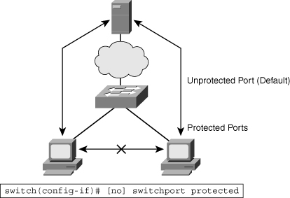
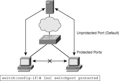
![]() Cisco lower-end switches, such as the Cisco 2960 series switches, don’t support Private VLANs, but they have a more limited feature, Private VLAN edge (protected port). Protected ports are a simple version of private VLANs. Traffic can flow only between a protected and unprotected port and between an unprotected and unprotected port. Traffic between protected ports is blocked. By default, ports are unprotected, as shown in Figure 2-19. In Figure 2-19, the two protected ports cannot communicate to each other, only with the unprotected ports.
Cisco lower-end switches, such as the Cisco 2960 series switches, don’t support Private VLANs, but they have a more limited feature, Private VLAN edge (protected port). Protected ports are a simple version of private VLANs. Traffic can flow only between a protected and unprotected port and between an unprotected and unprotected port. Traffic between protected ports is blocked. By default, ports are unprotected, as shown in Figure 2-19. In Figure 2-19, the two protected ports cannot communicate to each other, only with the unprotected ports.
![]() The Private VLAN edge (protected port) is a feature that has only local significance to the switch (unlike Private VLANs), and there is no isolation provided between two protected ports located on different switches. A protected port does not forward any traffic (unicast, multicast, or broadcast) to any other port that is also a protected port in the same switch. Traffic cannot be forwarded between protected ports at Layer 2. All traffic passing between protected ports must be forwarded through a Layer 3 (L3) device
The Private VLAN edge (protected port) is a feature that has only local significance to the switch (unlike Private VLANs), and there is no isolation provided between two protected ports located on different switches. A protected port does not forward any traffic (unicast, multicast, or broadcast) to any other port that is also a protected port in the same switch. Traffic cannot be forwarded between protected ports at Layer 2. All traffic passing between protected ports must be forwarded through a Layer 3 (L3) device

1 comments
Excellent article, huge thanks to the author!!!
Post a Comment