Implementing Trunking in Cisco Campus Network
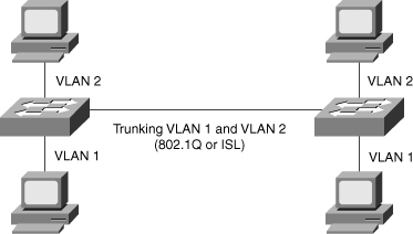
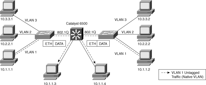
![]() Trunks carry the traffic for multiple VLANs across a single physical link (multiplexing). Trunking is used to extend Layer 2 operations across an entire network, such as end-to-end VLANs, as shown in Figure 2-6. The host in VLAN 2 can communicate with the host in VLAN 2 in the other switch over the single trunk link, the same as a host in VLAN 1 can communicate with a host in another switch in VLAN 1.
Trunks carry the traffic for multiple VLANs across a single physical link (multiplexing). Trunking is used to extend Layer 2 operations across an entire network, such as end-to-end VLANs, as shown in Figure 2-6. The host in VLAN 2 can communicate with the host in VLAN 2 in the other switch over the single trunk link, the same as a host in VLAN 1 can communicate with a host in another switch in VLAN 1.
![]() To allow a switchport that connect two switches to carry more than one VLAN, it must be configure as a trunk. If frames from a single VLAN traverse a trunk link, a trunking protocol must mark the frame to identify its associated VLAN as the frame is placed onto the trunk link. The receiving switch then knows the frame’s VLAN origin and can process the frame accordingly. On the receiving switch, the VLAN ID (VID) is removed when the frame is forwarded onto an access link associated with its VLAN.
To allow a switchport that connect two switches to carry more than one VLAN, it must be configure as a trunk. If frames from a single VLAN traverse a trunk link, a trunking protocol must mark the frame to identify its associated VLAN as the frame is placed onto the trunk link. The receiving switch then knows the frame’s VLAN origin and can process the frame accordingly. On the receiving switch, the VLAN ID (VID) is removed when the frame is forwarded onto an access link associated with its VLAN.
![]() When configuring an 802.1Q trunk, a matching native VLAN must be defined on each end of the trunk link. A trunk link is inherently associated with tagging each frame with a VID. The purpose of the native VLAN is to enable frames that are not tagged with a VID to traverse the trunk link. Native VLAN is discussed in more detail in a later part of this section.
When configuring an 802.1Q trunk, a matching native VLAN must be defined on each end of the trunk link. A trunk link is inherently associated with tagging each frame with a VID. The purpose of the native VLAN is to enable frames that are not tagged with a VID to traverse the trunk link. Native VLAN is discussed in more detail in a later part of this section.
![]() The following sections discuss trunking implementation, configuration, and troubleshooting in a multilayer switched network in more detail, including coverage of the following topics:
The following sections discuss trunking implementation, configuration, and troubleshooting in a multilayer switched network in more detail, including coverage of the following topics:
 Trunking Protocols
![]() This subsection covers the following two trunking protocols in more detail:
This subsection covers the following two trunking protocols in more detail:
-
 Inter-Switch Link (ISL): A Cisco proprietary trunking encapsulation
 -
 IEEE 802.1Q: An industry-standard trunking method
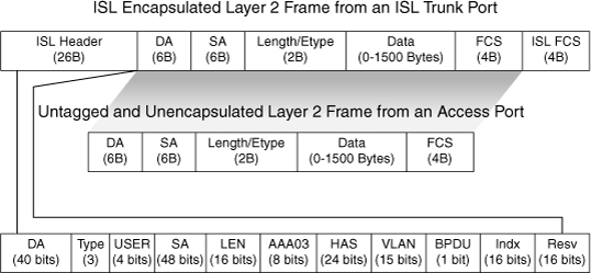
![]() Because ISL protocol is almost obsolete, this book focuses only on 802.1Q. Figure 2-7 depicts how ISL encapsulates the normal Ethernet frame. Currently, all Catalyst switches support 802.1Q tagging for multiplexing traffic from multiple VLANs onto a single physical link.
Because ISL protocol is almost obsolete, this book focuses only on 802.1Q. Figure 2-7 depicts how ISL encapsulates the normal Ethernet frame. Currently, all Catalyst switches support 802.1Q tagging for multiplexing traffic from multiple VLANs onto a single physical link.
![]() IEEE 802.1Q trunk links employ the tagging mechanism to carry frames for multiple VLANs, in which each frame is tagged to identify the VLAN to which the frame belongs. The IEEE 802.1Q/802.1p standard provides the following inherent architectural advantages over ISL:
IEEE 802.1Q trunk links employ the tagging mechanism to carry frames for multiple VLANs, in which each frame is tagged to identify the VLAN to which the frame belongs. The IEEE 802.1Q/802.1p standard provides the following inherent architectural advantages over ISL:
-
 802.1Q has smaller frame overhead than ISL. As a result, 802.1Q is more efficient than ISL, especially in the case of small frames. 802.1Q overhead is 4 bytes, whereas ISL is 30 bytes.
 -
 802.1Q is a widely supported industry-standard protocol.
 -
 802.1Q has the support for 802.1p fields for QoS.
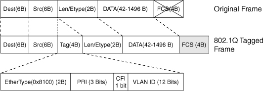
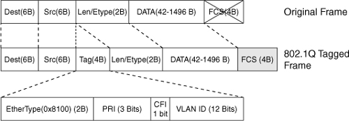
![]() Figure 2-8 describes the 802.1Q frame.
Figure 2-8 describes the 802.1Q frame.
![]() The 802.1Q Ethernet frame header contains the following fields:
The 802.1Q Ethernet frame header contains the following fields:
-
 Dest: Destination MAC address (6 bytes)
 -
 Src: Source MAC address (6 bytes)
 -
 Tag: Inserted 802.1Q tag (4 bytes, detailed here):
-
 EtherType(TPID): Set to 0x8100 to specify that the 802.1Q tag follows.
 -
 PRI: 3-bit 802.1p priority field.
 -
 CFI: Canonical Format Identifier; is always set to 0 for Ethernet switches and to 1 for Token Ring-type networks.
 -
 VLAN ID: 12-bit VLAN field. Of the 4096 possible VLAN IDs, the maximum number of possible VLAN configurations is 4094. A VLAN ID of 0 indicates priority frames, and value 4095 (FFF) is reserved. CFI, PRI, and VLAN ID are represented as Tag Control information (TCI) fields.
-
-
 Len/Etype: 2-byte field specifying length (802.3) or type (Ethernet II).
 -
 Data: Data itself.
 -
 FCS: Frame check sequence (4 bytes).
![]() IEEE 802.1Q uses an internal tagging mechanism that modifies the original frame (as shown by the “X” over FCS in the original frame in Figure 2-8), recalculates the CRC value for the entire frame with the tag, and inserts the new CRC value in a new FCS. ISL, in comparison, wraps the original frame and adds a second FCS that is built only on the header information but does not modify the original frame FCS.
IEEE 802.1Q uses an internal tagging mechanism that modifies the original frame (as shown by the “X” over FCS in the original frame in Figure 2-8), recalculates the CRC value for the entire frame with the tag, and inserts the new CRC value in a new FCS. ISL, in comparison, wraps the original frame and adds a second FCS that is built only on the header information but does not modify the original frame FCS.
![]() IEEE 802.1p redefined the three most significant bits in the 802.1Q tag to allow for prioritization of the Layer 2 frame.
IEEE 802.1p redefined the three most significant bits in the 802.1Q tag to allow for prioritization of the Layer 2 frame.
![]() If a non-802.1Q-enabled device or an access port receives an 802.1Q frame, the tag data is ignored and the packet is switched at Layer 2 as a standard Ethernet frame. This allows for the placement of Layer 2 intermediate devices, such as unmanaged switches or bridges, along the 802.1Q trunk path. To process an 802.1Q tagged frame, a device must enable a maximum transmission unit (MTU) of 1522 or higher.
If a non-802.1Q-enabled device or an access port receives an 802.1Q frame, the tag data is ignored and the packet is switched at Layer 2 as a standard Ethernet frame. This allows for the placement of Layer 2 intermediate devices, such as unmanaged switches or bridges, along the 802.1Q trunk path. To process an 802.1Q tagged frame, a device must enable a maximum transmission unit (MTU) of 1522 or higher.
![]() Baby giants are frames that are larger than the standard MTU of 1500 bytes but less than 2000 bytes. Because ISL and 802.1Q tagged frames increase the MTU beyond 1500 bytes, switches consider both frames as baby giants. ISL-encapsulated packets over Ethernet have an MTU of 1548 bytes, whereas 802.1Q has an MTU of 1522 bytes.
Baby giants are frames that are larger than the standard MTU of 1500 bytes but less than 2000 bytes. Because ISL and 802.1Q tagged frames increase the MTU beyond 1500 bytes, switches consider both frames as baby giants. ISL-encapsulated packets over Ethernet have an MTU of 1548 bytes, whereas 802.1Q has an MTU of 1522 bytes.
Understanding Native VLAN in 802.1Q Trunking
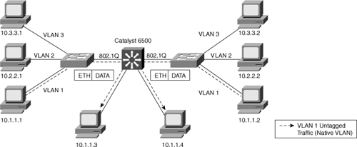
![]() 802.1Q trunks define a native VLAN for frames that are not tagged by default. Switches transmit any Layer 2 frames from a native VLAN on the trunk port untagged, as shown in Figure 2-9. The receiving switch forwards all untagged packets to its native VLAN. The native VLAN is the default VLAN configuration of the port. When the port is not trunking, the access VLAN configuration defines the native VLAN. In the case of Cisco switches, the default native VLAN is VLAN 1, and you can configure any other VLAN as the native VLAN.
802.1Q trunks define a native VLAN for frames that are not tagged by default. Switches transmit any Layer 2 frames from a native VLAN on the trunk port untagged, as shown in Figure 2-9. The receiving switch forwards all untagged packets to its native VLAN. The native VLAN is the default VLAN configuration of the port. When the port is not trunking, the access VLAN configuration defines the native VLAN. In the case of Cisco switches, the default native VLAN is VLAN 1, and you can configure any other VLAN as the native VLAN.
![]() It is important that the 802.1Q trunk port between two devices have the same native VLAN configuration on both sides of the link. If there is a native VLAN mismatch on an 802.1Q link, CDP (if used and functioning) issues a Native VLAN Mismatch error. On select versions of Cisco IOS Software, CDP might not be transmitted or will be automatically turned off if VLAN1 is disabled on the trunk.
It is important that the 802.1Q trunk port between two devices have the same native VLAN configuration on both sides of the link. If there is a native VLAN mismatch on an 802.1Q link, CDP (if used and functioning) issues a Native VLAN Mismatch error. On select versions of Cisco IOS Software, CDP might not be transmitted or will be automatically turned off if VLAN1 is disabled on the trunk.
![]() In addition, if there is a native VLAN mismatch on either side of an 802.1Q link, Layer 2 loops might occur because VLAN1 STP bridge protocol data units (BPDU) are sent to the IEEE STP MAC address (0180.c200.0000) untagged.
In addition, if there is a native VLAN mismatch on either side of an 802.1Q link, Layer 2 loops might occur because VLAN1 STP bridge protocol data units (BPDU) are sent to the IEEE STP MAC address (0180.c200.0000) untagged.
 Understanding DTP
![]() All recent Cisco Catalyst switches, except for the Catalyst 2900XL and 3500XL, use a Cisco proprietary point-to-point protocol called Dynamic Trunking Protocol (DTP) on trunk ports to negotiate the trunking state. DTP negotiates the operational mode of directly connected switch ports to a trunk port and selects an appropriate trunking protocol. Negotiating trunking is a recommended practice in multilayer switched networks because it avoids network issues resulting from trunking misconfigurations for initial configuration, but best practice is when the network is stable, change to permanent trunk.
All recent Cisco Catalyst switches, except for the Catalyst 2900XL and 3500XL, use a Cisco proprietary point-to-point protocol called Dynamic Trunking Protocol (DTP) on trunk ports to negotiate the trunking state. DTP negotiates the operational mode of directly connected switch ports to a trunk port and selects an appropriate trunking protocol. Negotiating trunking is a recommended practice in multilayer switched networks because it avoids network issues resulting from trunking misconfigurations for initial configuration, but best practice is when the network is stable, change to permanent trunk.
Cisco Trunking Modes and Methods
![]() Table 2-4 describes the different trunking modes supported by Cisco switches.
Table 2-4 describes the different trunking modes supported by Cisco switches.
|
|
|
|---|---|
|
|
|
|
|
|
|
|
|
|
|
|
|
|
|
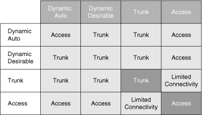
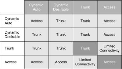
![]() Figure 2-10 shows the combination of DTP modes between the two links. Combination of DTP modes can either make the port as an access port or trunk port.
Figure 2-10 shows the combination of DTP modes between the two links. Combination of DTP modes can either make the port as an access port or trunk port.
VLAN Ranges and Mappings
![]() ISL supports VLAN numbers in the range of 1 to 1005, whereas 802.1Q VLAN numbers are in the range of 1 to 4094. The default behavior of VLAN trunks is to permit all normal- and extended-range VLANs across the link if it is an 802.1Q interface and to permit normal VLANs in the case of an ISL interface.
ISL supports VLAN numbers in the range of 1 to 1005, whereas 802.1Q VLAN numbers are in the range of 1 to 4094. The default behavior of VLAN trunks is to permit all normal- and extended-range VLANs across the link if it is an 802.1Q interface and to permit normal VLANs in the case of an ISL interface.
 Best Practices for Trunking
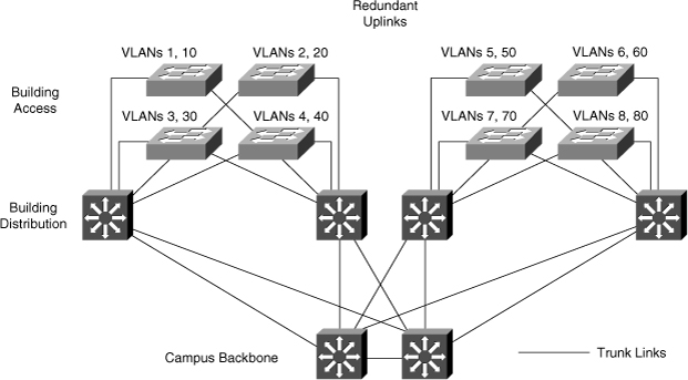
![]() In a hierarchical design, access layer switches connect to distribution layer switches. This is where the trunks are implementing, as illustrated in Figure 2-11, where the links from each access switch to the distribution switches are the trunks links because they must carry two VLANs from each switch. Links between distribution and core layers are usually Layer 3. Also, usually to avoid spanning-tree problems, it is recommended not to link the two distribution switches as Layer 2 trunk links or have no link between them. In this way, the access layer switches are configured as a spanning-tree, loop-free V topology if one distribution link fails, using the HSRP or VRRP protocols for creating a virtual default-gateway. Spanning tree, HSRP, and VRRP are discussed more in later chapters.
In a hierarchical design, access layer switches connect to distribution layer switches. This is where the trunks are implementing, as illustrated in Figure 2-11, where the links from each access switch to the distribution switches are the trunks links because they must carry two VLANs from each switch. Links between distribution and core layers are usually Layer 3. Also, usually to avoid spanning-tree problems, it is recommended not to link the two distribution switches as Layer 2 trunk links or have no link between them. In this way, the access layer switches are configured as a spanning-tree, loop-free V topology if one distribution link fails, using the HSRP or VRRP protocols for creating a virtual default-gateway. Spanning tree, HSRP, and VRRP are discussed more in later chapters.
![]() DTP is useful when the status of the switch on the other end of the link is uncertain or might be changing over time. When the link is to be set to trunk in a stable manner, changing both ends to trunk nonegotiate accelerates the convergence time, saving up to two seconds upon boot time. We recommend this mode on stable links between switches that are part of the same core infrastructure.
DTP is useful when the status of the switch on the other end of the link is uncertain or might be changing over time. When the link is to be set to trunk in a stable manner, changing both ends to trunk nonegotiate accelerates the convergence time, saving up to two seconds upon boot time. We recommend this mode on stable links between switches that are part of the same core infrastructure.
![]() On trunk links, it is recommended to manually prune the VLANs that are not used. You can use VTP pruning if VTP is in use, but manual pruning (using a switchport trunk allowed VLAN) is a secure way of allowing only those VLANs that are expected and allowed on the link. In addition to this, it is also a good practice to have an unused VLAN as a native VLAN on the trunk links to prevent DTP spoofing.
On trunk links, it is recommended to manually prune the VLANs that are not used. You can use VTP pruning if VTP is in use, but manual pruning (using a switchport trunk allowed VLAN) is a secure way of allowing only those VLANs that are expected and allowed on the link. In addition to this, it is also a good practice to have an unused VLAN as a native VLAN on the trunk links to prevent DTP spoofing.
![]() If trunking is not used on a port, you can disable it with the interface level command switchport host. This command is a macro that sets the port to access mode (switchport mode access) and enables portfast.
If trunking is not used on a port, you can disable it with the interface level command switchport host. This command is a macro that sets the port to access mode (switchport mode access) and enables portfast.
 Configuring 802.1Q Trunking
![]() To configure a switch port as an 802.1Q trunking port in Cisco IOS, use the following commands:
To configure a switch port as an 802.1Q trunking port in Cisco IOS, use the following commands:
| Note |
|
![]() Example 2-9 shows the configuration of interface Fast Ethernet 5/8 for 802.1Q trunking in the desirable mode and allowing only VLANs 1 through 100 on the trunk.
Example 2-9 shows the configuration of interface Fast Ethernet 5/8 for 802.1Q trunking in the desirable mode and allowing only VLANs 1 through 100 on the trunk.
Switch# configure terminal
Enter configuration commands, one per line. End with CNTL/Z.
Switch(config)# interface FastEthernet 5/8
Switch(config-if)# switchport trunk encapsulation dot1q
Switch(config-if)# switchport mode dynamic desirable
Switch(config-if)# switchport trunk allowed vlan 1-100
Switch(config-if)# no shutdown
Switch(config-if)# end
 Verifying Trunking Configurations
![]() To verify the trunk configuration in Cisco IOS, use the commands in Table 2-5.
To verify the trunk configuration in Cisco IOS, use the commands in Table 2-5.
|
|
|
|---|---|
|
|
|
|
|
|
|
|
|
![]() Example 2-10 displays port configuration for trunking.
Example 2-10 displays port configuration for trunking.
Switch# show running-config interface FastEthernet 5/8
Building configuration...
Current configuration:
!
interface FastEthernet5/8
switchport mode dynamic desirable
switchport trunk encapsulation dot1q
end
![]() Example 2-11 displays switchport information about interface FastEthernet 5/8, which is operating as an 802.1Q trunk.
Example 2-11 displays switchport information about interface FastEthernet 5/8, which is operating as an 802.1Q trunk.
Switch# show interfaces FastEthernet 5/8 switchport
Name: Fa5/8
Switchport: Enabled
Administrative Mode: dynamic desirable
Operational Mode: trunk
Administrative Trunking Encapsulation: negotiate
Operational Trunking Encapsulation: dot1q
Negotiation of Trunking: Enabled
Access Mode VLAN: 1 (default)
Trunking Native Mode VLAN: 1 (default)
Trunking VLANs Enabled: ALL
Pruning VLANs Enabled: 2-1001
![]() Example 2-12 displays trunk information for a particular port.
Example 2-12 displays trunk information for a particular port.
Switch# show interfaces FastEthernet 5/8 trunk

Port      Mode          Encapsulation  Status        Native vlan
Fa5/8     desirable     n-802.1q       trunking      1

Port      Vlans allowed on trunk
Fa5/8     1-1005

Port      Vlans allowed and active in management domain
Fa5/8     1-6,10,20,50,100,152,200,300,303-305,349-351,400,500,521,524,570,801-8
         02,850,917,999,1002-1005

Port      Vlans in spanning tree forwarding state and not pruned
Fa5/8     1-6,10,20,50,100,152,200,300,303-305,349-351,400,500,521,524,570,801-8
         02,850,917,999,1002-1005
 Troubleshooting Trunking
![]() To troubleshoot a problem with a trunk port, verify that the following configurations are correct:
To troubleshoot a problem with a trunk port, verify that the following configurations are correct:
-
 Interface modes
 -
 Native VLAN
 -
 Encapsulation types
![]() A common problem with VLANs is where a device cannot establish a connection across a trunk link. Suggested solutions to the problem are as follows:
A common problem with VLANs is where a device cannot establish a connection across a trunk link. Suggested solutions to the problem are as follows:
-
 Ensure that the Layer 2 interface mode configured on both ends of the link is valid. The trunk mode should be trunk or desirable for at least one side of the trunk. Use the show interface interface_id trunk command in Cisco IOS to verify the configuration.
 -
 Ensure that the trunk encapsulation type configured on both ends of the link is valid and compatible.
 -
 On IEEE 802.1Q trunks, make sure that the native VLAN is the same on both ends of the trunk.
 -
 When using DTP, ensure that both ends of the link are in the same VTP domain.
VLAN Trunking Protocol
![]() VTP is a protocol that is used to distribute and synchronize information about VLAN databases configured throughout a switched network. VTP minimizes misconfigurations and configuration inconsistencies that might result in various problems, such as duplicate VLAN names, incorrect VLAN-type specifications, and security violations. Switches transmit VTP messages only on 802.1Q or ISL trunks. Cisco switches transmit VTP summary advertisements over the management VLAN (VLAN 1 by default) using a Layer 2 multicast frame every 5 minutes. VTP packets are sent to the destination MAC address 01-00-0C-CC-CC-CC with a logical link control (LLC) code of Subnetwork Access Protocol (SNAP) (AAAA) and a type of 2003 (in the SNAP header).
VTP is a protocol that is used to distribute and synchronize information about VLAN databases configured throughout a switched network. VTP minimizes misconfigurations and configuration inconsistencies that might result in various problems, such as duplicate VLAN names, incorrect VLAN-type specifications, and security violations. Switches transmit VTP messages only on 802.1Q or ISL trunks. Cisco switches transmit VTP summary advertisements over the management VLAN (VLAN 1 by default) using a Layer 2 multicast frame every 5 minutes. VTP packets are sent to the destination MAC address 01-00-0C-CC-CC-CC with a logical link control (LLC) code of Subnetwork Access Protocol (SNAP) (AAAA) and a type of 2003 (in the SNAP header).
![]() VTP is a Layer 2 messaging protocol that maintains VLAN configuration consistency by managing the additions, deletions, and name changes of VLANs within a VTP domain.
VTP is a Layer 2 messaging protocol that maintains VLAN configuration consistency by managing the additions, deletions, and name changes of VLANs within a VTP domain.
![]() A VTP domain is one switch or several interconnected switches that share the same VTP environment. Catalyst switches support only a single VTP domain per switch.
A VTP domain is one switch or several interconnected switches that share the same VTP environment. Catalyst switches support only a single VTP domain per switch.
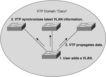
![]() By default, a Catalyst switch is in the no-management-domain state until it receives an advertisement for a VTP domain over a trunk link or until a VTP configuration is applied, as shown in Figure 2-12.
By default, a Catalyst switch is in the no-management-domain state until it receives an advertisement for a VTP domain over a trunk link or until a VTP configuration is applied, as shown in Figure 2-12.
![]() Configurations made to a single VTP server propagate across trunk links to all connected switches in the network in the following manner:
Configurations made to a single VTP server propagate across trunk links to all connected switches in the network in the following manner:
|
|
|
|
|
|
|
|
|
![]() VTP operates in one of the following modes: server mode, client mode, transparent mode, or off mode. The default VTP mode is server mode, but Catalyst switches do not propagate VTP information out trunk interfaces until a management domain name is specified or learned.
VTP operates in one of the following modes: server mode, client mode, transparent mode, or off mode. The default VTP mode is server mode, but Catalyst switches do not propagate VTP information out trunk interfaces until a management domain name is specified or learned.
![]() Table 2-6 describes the features of the VTP client, server, transparent, and off modes.
Table 2-6 describes the features of the VTP client, server, transparent, and off modes.
|
|
|
|---|---|
|
|
|
|
|
|
|
|
|
| Note |
|
![]() A device that receives VTP summary advertisements checks various parameters before incorporating the received VLAN information. First, the management domain name and password in the advertisement must match those configured in the local switch. Next, if the configuration revision number indicates that the message was created after the configuration currently in use, the switch incorporates the advertised VLAN information if the switch is a VTP server or client.
A device that receives VTP summary advertisements checks various parameters before incorporating the received VLAN information. First, the management domain name and password in the advertisement must match those configured in the local switch. Next, if the configuration revision number indicates that the message was created after the configuration currently in use, the switch incorporates the advertised VLAN information if the switch is a VTP server or client.
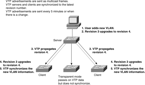
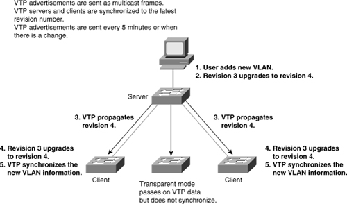
![]() One of the most critical components of VTP is the configuration revision number. Each time a VTP server modifies its VLAN information, it increments the configuration revision number by 1. It then sends out a VTP subnet advertisement with the new configuration revision number. If the configuration revision number that is advertised is higher than the number stored on the other switches in the VTP domain, the rest of the switches in the domain overwrite their VLAN configurations with the new information advertised, as shown in Figure 2-13.
One of the most critical components of VTP is the configuration revision number. Each time a VTP server modifies its VLAN information, it increments the configuration revision number by 1. It then sends out a VTP subnet advertisement with the new configuration revision number. If the configuration revision number that is advertised is higher than the number stored on the other switches in the VTP domain, the rest of the switches in the domain overwrite their VLAN configurations with the new information advertised, as shown in Figure 2-13.
![]() Because a VTP-transparent switch does not participate in VTP, that switch does not advertise its VLAN configuration or synchronize its VLAN database upon receipt of a VTP advertisement.
Because a VTP-transparent switch does not participate in VTP, that switch does not advertise its VLAN configuration or synchronize its VLAN database upon receipt of a VTP advertisement.
| Note |
|
![]() The ensuing sections discuss the following properties of VTP:
The ensuing sections discuss the following properties of VTP:
 VTP Pruning
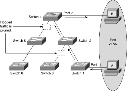
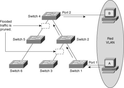
![]() VTP pruning uses VLAN advertisements to determine when a trunk connection is flooding traffic needlessly. By default, a trunk connection carries traffic for all VLANs in the VTP management domain. Commonly, some switches in an enterprise network do not have local ports configured in each VLAN. In Figure 2-14, Switches 1 and 4 support ports statically configured in the red VLAN.
VTP pruning uses VLAN advertisements to determine when a trunk connection is flooding traffic needlessly. By default, a trunk connection carries traffic for all VLANs in the VTP management domain. Commonly, some switches in an enterprise network do not have local ports configured in each VLAN. In Figure 2-14, Switches 1 and 4 support ports statically configured in the red VLAN.
![]() VTP pruning increases available bandwidth by restricting flooded traffic to those trunk links that the traffic must use to access the appropriate network devices. Figure 2-14 shows a switched network with VTP pruning enabled. The broadcast traffic from Station A is not forwarded to Switches 3, 5, and 6 because traffic for the red VLAN has been pruned on the links indicated on Switches 2 and 4.
VTP pruning increases available bandwidth by restricting flooded traffic to those trunk links that the traffic must use to access the appropriate network devices. Figure 2-14 shows a switched network with VTP pruning enabled. The broadcast traffic from Station A is not forwarded to Switches 3, 5, and 6 because traffic for the red VLAN has been pruned on the links indicated on Switches 2 and 4.
| Note |
|
 VTP Versions
![]() Cisco Catalyst switches support three different versions of VTP: versions 1, 2, and 3. It is important to decide which version to use because they are not interoperable. In addition, Cisco recommends running only one VTP version for network stability. This chapter emphasizes VTP versions 1 and 2 because VTP version 3 is not the most frequently used version of the VTP.
Cisco Catalyst switches support three different versions of VTP: versions 1, 2, and 3. It is important to decide which version to use because they are not interoperable. In addition, Cisco recommends running only one VTP version for network stability. This chapter emphasizes VTP versions 1 and 2 because VTP version 3 is not the most frequently used version of the VTP.
VTP Versions 1 and 2
![]() VTP version 2 supports these features that are not implemented in VTP version 1:
VTP version 2 supports these features that are not implemented in VTP version 1:
-
 Token Ring support: VTP version 2 supports Token Ring LAN switching and Token Ring VLANs.
 -
 Unrecognized Type-Length-Value (TLV) support: A VTP version 2 server or client propagates configuration changes to its other trunks even for TLVs that it cannot parse. VTP version 2 servers can still save unrecognized TLVs in NVRAM. This could be useful if not all devices are at the same version or release level.
Note  TLV optional information may be encoded as a type-length-value or TLV element inside the protocol. One of the advantages of using a TLV representation is that TLV sequences are easily searched using generalized parsing functions.
 -
 Version-independent transparent mode: In VTP version 1, a VTP-transparent switch inspects VTP messages for the domain name and version and forwards a message only if the version and domain name match. Because only one domain is supported in the Supervisor Engine software, VTP version 2 forwards VTP messages in transparent mode—without checking the version.
 -
 Consistency checks: VTP version 2 performs VLAN consistency checks (such as VLAN names and values) only when you enter new information through the CLI or via the Simple Network Management Protocol (SNMP). VTP version 2 does not perform checks when new information is obtained from a VTP message or when information is read from NVRAM. If the message digest algorithm 5 (MD5) on a received VTP message is correct, VTP version 2 accepts the information. Use VTP version 2 in a Token Ring environment, because VTP version 1 does not support Token Ring VLANs.
![]() If all switches in a domain are capable of running VTP version 2, enable VTP version 2 on one VTP server. The VTP server propagates the version number to the other VTP version 2–capable switches in the VTP domain.
If all switches in a domain are capable of running VTP version 2, enable VTP version 2 on one VTP server. The VTP server propagates the version number to the other VTP version 2–capable switches in the VTP domain.
VTP Version 3
![]() VTP version 3 is supported in Cisco CatOS Software versions 8.1 and above and all the latest Cisco IOS images. VTP version 3 differs from earlier VTP versions in that it does not directly handle VLANs. Instead, it is responsible for distributing a list of databases over an administrative domain. The following items are enhancements in VTP version 3:
VTP version 3 is supported in Cisco CatOS Software versions 8.1 and above and all the latest Cisco IOS images. VTP version 3 differs from earlier VTP versions in that it does not directly handle VLANs. Instead, it is responsible for distributing a list of databases over an administrative domain. The following items are enhancements in VTP version 3:
-
 Support for extended VLANs (1025 to 4094)
 -
 Support for the creation and advertising of Private VLANs
 -
 Improved server authentication
 -
 Enhancements to a mechanism for protection from the “wrong” database accidentally being inserted into a VTP domain
 -
 Interaction with VTP versions 1 and 2
 -
 Configurable on a per-port basis
| Note |
|
![]() VTP version 3 has the same features as VTP versions 1 and 2 except for the addition of the modes of primary and secondary server and the concept of database consistency.
VTP version 3 has the same features as VTP versions 1 and 2 except for the addition of the modes of primary and secondary server and the concept of database consistency.
| Note |
|
 VTP Messages Types
![]() VTP uses various messages types for its communication. The following are the message types for VTP.
VTP uses various messages types for its communication. The following are the message types for VTP.
Summary Advertisements
![]() By default, Catalyst switches issue summary advertisements in 5-minute increments. Summary advertisements inform adjacent Catalysts of the current VTP domain name and the configuration revision number.
By default, Catalyst switches issue summary advertisements in 5-minute increments. Summary advertisements inform adjacent Catalysts of the current VTP domain name and the configuration revision number.
![]() When the switch receives a summary advertisement packet, the switch compares the VTP domain name to its own VTP domain name. If the name is different, the switch simply ignores the packet. If the name is the same, the switch then compares the configuration revision to its own revision. If its own configuration revision is higher or equal, the packet is ignored. If it is lower, an advertisement request is sent.
When the switch receives a summary advertisement packet, the switch compares the VTP domain name to its own VTP domain name. If the name is different, the switch simply ignores the packet. If the name is the same, the switch then compares the configuration revision to its own revision. If its own configuration revision is higher or equal, the packet is ignored. If it is lower, an advertisement request is sent.
Subset Advertisements
![]() When you add, delete, or change a VLAN in a Catalyst, the server Catalyst where the changes are made increments the configuration revision and issues a summary advertisement. One or several subset advertisements follow the summary advertisement. A subset advertisement contains a list of VLAN information. If there are several VLANs, more than one subset advertisement can be required to advertise all the VLANs.
When you add, delete, or change a VLAN in a Catalyst, the server Catalyst where the changes are made increments the configuration revision and issues a summary advertisement. One or several subset advertisements follow the summary advertisement. A subset advertisement contains a list of VLAN information. If there are several VLANs, more than one subset advertisement can be required to advertise all the VLANs.
Advertisement Requests
![]() A switch needs a VTP advertisement request in these situations:
A switch needs a VTP advertisement request in these situations:
-
 The switch has been reset.
 -
 The VTP domain name has been changed.
 -
 The switch has received a VTP summary advertisement with a higher configuration revision than its own.
![]() Upon receipt of an advertisement request, a VTP device sends a summary advertisement. One or more subset advertisements follow the summary advertisement.
Upon receipt of an advertisement request, a VTP device sends a summary advertisement. One or more subset advertisements follow the summary advertisement.
 VTP Authentication
![]() VTP domains can be secured by using the VTP password feature. It is important to make sure that all the switches in the VTP domain have the same password and domain name; otherwise, a switch will not become a member of the VTP domain. Cisco switches use MD5 to encode passwords in 16-byte words. These passwords propagate inside VTP summary advertisements. In VTP, passwords are case-sensitive and can be 8 to 64 characters in length. The use of VTP authentication is a recommended practice.
VTP domains can be secured by using the VTP password feature. It is important to make sure that all the switches in the VTP domain have the same password and domain name; otherwise, a switch will not become a member of the VTP domain. Cisco switches use MD5 to encode passwords in 16-byte words. These passwords propagate inside VTP summary advertisements. In VTP, passwords are case-sensitive and can be 8 to 64 characters in length. The use of VTP authentication is a recommended practice.
 Best Practices for VTP implementation
![]() VTP is often used in a new network to facilitate the implementation of VLANs. However, as the network grows larger, this benefit can turn into a liability. If a VLAN is deleted by accident on one server, it is deleted throughout the network. If a switch that already has a VLAN database defined is inserted into the network, it can hijack the VLAN database by deleting added VLANs. Because of this, it is the recommended practice to configure all switches to transparent VTP mode and manually add VLANs as needed, especially in a larger campus network. Usually VTP configuration is good for small environments.
VTP is often used in a new network to facilitate the implementation of VLANs. However, as the network grows larger, this benefit can turn into a liability. If a VLAN is deleted by accident on one server, it is deleted throughout the network. If a switch that already has a VLAN database defined is inserted into the network, it can hijack the VLAN database by deleting added VLANs. Because of this, it is the recommended practice to configure all switches to transparent VTP mode and manually add VLANs as needed, especially in a larger campus network. Usually VTP configuration is good for small environments.
 Configuring VTP
![]() To configure a VTP server in Cisco IOS in configuration mode for VTP versions 1 and 2, follow these steps from privileged EXEC mode:
To configure a VTP server in Cisco IOS in configuration mode for VTP versions 1 and 2, follow these steps from privileged EXEC mode:
|
|
|
|
|
|
|
|
|
|
|
|
|
|
|
|
|
|
| Note |
|
![]() Example 2-13 shows configuration of a Catalyst switch as a VTP server in Cisco IOS in global configuration mode.
Example 2-13 shows configuration of a Catalyst switch as a VTP server in Cisco IOS in global configuration mode.
Switch# configure terminal
Switch(config)# vtp mode server
Setting device to VTP SERVER mode.
Switch(config)# vtp domain Lab_Network
Switch(config)# end
 Verifying the VTP Configuration
![]() Use the show vtp status command to display information about the VTP configuration and current state in Cisco IOS.
Use the show vtp status command to display information about the VTP configuration and current state in Cisco IOS.
![]() Example 2-14 shows how to verify the VTP configuration by using the show vtp status command. The output describes the VTP version, number of VLANs supported locally, VTP operating mode, VTP domain name, and VTP pruning mode.
Example 2-14 shows how to verify the VTP configuration by using the show vtp status command. The output describes the VTP version, number of VLANs supported locally, VTP operating mode, VTP domain name, and VTP pruning mode.
Switch# show vtp status

VTP Version                       : 2
Configuration Revision            : 247
Maximum VLANs supported locally   : 1005
Number of existing VLANs          : 33
VTP Operating Mode                : Server
VTP Domain Name                   : Lab_Network
VTP Pruning Mode                  : Enabled
VTP V2 Mode                       : Disabled
VTP Traps Generation              : Disabled
MD5 digest                        : 0x45 0x52 0xB6 0xFD 0x63 0xC8 0x49 0x80
Configuration last modified by 0.0.0.0 at 8-12-99 15:04:4
![]() Use the show vtp counters command to display statistics about VTP operation. Example 2-15 displays VTP statistics in Cisco IOS. If there are any problems regarding the VTP operation, the show command in Example 2-15 helps look for VTP message type updates.
Use the show vtp counters command to display statistics about VTP operation. Example 2-15 displays VTP statistics in Cisco IOS. If there are any problems regarding the VTP operation, the show command in Example 2-15 helps look for VTP message type updates.
Switch# show vtp counters

VTP statistics:
Summary advertisements received     : 7
Subset advertisements received      : 5
Request advertisements received     : 0
Summary advertisements transmitted  : 997
Subset advertisements transmitted   : 13
Request advertisements transmitted  : 3
Number of config revision errors    : 0
Number of config digest errors      : 0
Number of V1 summary errors         : 0

VTP pruning statistics:

Trunk            Join Transmitted Join Received    Summary advts received from
                                              non-pruning-capable device
---------------- ---------------- ---------------- ------------------
Fa5/8                43071             42766             5
 Troubleshooting VTP
![]() Problems with VTP configuration are usually a result of improperly configured trunk links, domain names, VTP modes, or passwords.
Problems with VTP configuration are usually a result of improperly configured trunk links, domain names, VTP modes, or passwords.
![]() Perform the following steps to troubleshoot VTP issues in which VTP is not updating the configuration on other switches when VLAN configuration changes occur:
Perform the following steps to troubleshoot VTP issues in which VTP is not updating the configuration on other switches when VLAN configuration changes occur:
|
|
|
|
|
|
|
|
|
|
|
|

0 comments
Post a Comment