
Configuring and Verifying EIGRP Authentication
![]() You can prevent your router from receiving fraudulent route updates by configuring neighbor router authentication. You can configure EIGRP neighbor authentication (also called neighbor router authentication or route authentication) such that routers can participate in routing based on predefined passwords.
You can prevent your router from receiving fraudulent route updates by configuring neighbor router authentication. You can configure EIGRP neighbor authentication (also called neighbor router authentication or route authentication) such that routers can participate in routing based on predefined passwords.
![]() This section first describes router authentication in general, followed by a discussion of how to configure and troubleshoot EIGRP message digest 5 (MD5) authentication.
This section first describes router authentication in general, followed by a discussion of how to configure and troubleshoot EIGRP message digest 5 (MD5) authentication.
 Router Authentication
![]() You can configure neighbor router authentication such that routers only participate in routing based on predefined passwords.
You can configure neighbor router authentication such that routers only participate in routing based on predefined passwords.
![]() By default, no authentication is used for routing protocol packets. Without neighbor authentication, unauthorized or deliberately malicious routing updates could compromise the security of network traffic. For example, an unauthorized router connected to the network (by someone with malicious or innocent intentions) could send a fictitious routing update to convince your router to send traffic to an incorrect destination.
By default, no authentication is used for routing protocol packets. Without neighbor authentication, unauthorized or deliberately malicious routing updates could compromise the security of network traffic. For example, an unauthorized router connected to the network (by someone with malicious or innocent intentions) could send a fictitious routing update to convince your router to send traffic to an incorrect destination.
![]() When neighbor router authentication has been configured on a router, the router authenticates the source of each routing protocol packet that it receives. This is accomplished by the exchange of an authentication key (also called a password) that is known to both the sending and the receiving router.
When neighbor router authentication has been configured on a router, the router authenticates the source of each routing protocol packet that it receives. This is accomplished by the exchange of an authentication key (also called a password) that is known to both the sending and the receiving router.
Simple Authentication Versus MD5 Authentication
![]() Routers use two types of authentication:
Routers use two types of authentication:
- Simple password authentication (also called plain-text authentication)— Supported by Integrated System-Integrated System (IS-IS) Protocol, OSPF, and Routing Information Protocol Version 2 (RIPv2)
- MD5 authentication— Supported by OSPF, RIPv2, BGP, and EIGRP
| Note |
|
![]() Both forms of authentication work in the same way, with the exception that MD5 sends a message digest rather than the authenticating key itself. The message digest is created using the key (and a key ID with some protocols) and a message, but the key itself is not sent, preventing it from being read while it is being transmitted. Simple password authentication sends the authenticating key itself over the wire.
Both forms of authentication work in the same way, with the exception that MD5 sends a message digest rather than the authenticating key itself. The message digest is created using the key (and a key ID with some protocols) and a message, but the key itself is not sent, preventing it from being read while it is being transmitted. Simple password authentication sends the authenticating key itself over the wire.
| Note |
|
| Caution |
|
![]() With simple password authentication, a password (key) is configured on a router; each participating neighbor router must be configured with the same key. When a packet is sent, the password is included in plain text.
With simple password authentication, a password (key) is configured on a router; each participating neighbor router must be configured with the same key. When a packet is sent, the password is included in plain text.
![]() MD5 authentication, described in RFC 1321, The MD5 Message-Digest Algorithm, is a cryptographic authentication. A key (password) and key ID are configured on each router. The router uses an algorithm based on the routing protocol packet, the key, and the key ID to generate a message digest (also called a hash) that is appended to the packet. Unlike the simple authentication, the key is not exchanged over the wire—the message digest is sent instead of the key, which ensures that nobody can eavesdrop on the line and learn keys during transmission.
MD5 authentication, described in RFC 1321, The MD5 Message-Digest Algorithm, is a cryptographic authentication. A key (password) and key ID are configured on each router. The router uses an algorithm based on the routing protocol packet, the key, and the key ID to generate a message digest (also called a hash) that is appended to the packet. Unlike the simple authentication, the key is not exchanged over the wire—the message digest is sent instead of the key, which ensures that nobody can eavesdrop on the line and learn keys during transmission.
| Note |
|
MD5 Authentication for EIGRP
![]() By default, no authentication is used for EIGRP packets. You can configure EIGRP to use MD5 authentication.
By default, no authentication is used for EIGRP packets. You can configure EIGRP to use MD5 authentication.
![]() When EIGRP neighbor authentication has been configured on a router, the router authenticates the source of each routing protocol packet that it receives. The MD5 keyed digest in each EIGRP packet prevents the introduction of unauthorized or false routing messages from unapproved sources.
When EIGRP neighbor authentication has been configured on a router, the router authenticates the source of each routing protocol packet that it receives. The MD5 keyed digest in each EIGRP packet prevents the introduction of unauthorized or false routing messages from unapproved sources.
![]() For EIGRP MD5 authentication, you must configure an authenticating key and a key ID on both the sending router and the receiving router. Each EIGRP router takes the key and key ID and generates message digest that is appended to each routing protocol packet and sent to the neighbor. The receiving router computes the MD5 hash from the received EIGRP information. If the hash matches with the value received, the packet is accepted. If there is no match, the packet is silently dropped.
For EIGRP MD5 authentication, you must configure an authenticating key and a key ID on both the sending router and the receiving router. Each EIGRP router takes the key and key ID and generates message digest that is appended to each routing protocol packet and sent to the neighbor. The receiving router computes the MD5 hash from the received EIGRP information. If the hash matches with the value received, the packet is accepted. If there is no match, the packet is silently dropped.
![]() Each key has its own key ID, which is stored locally. The combination of the key ID and the interface associated with the message uniquely identifies the authentication algorithm and MD5 authentication key in use.
Each key has its own key ID, which is stored locally. The combination of the key ID and the interface associated with the message uniquely identifies the authentication algorithm and MD5 authentication key in use.
![]() You can increase the security of EIGRP MD5 authentication by making frequent key changes. You can define and activate multiple keys based on time, as defined in the configuration. Transition between the keys is implemented in such way that it allows a nondisruptive operation of EIGRP exchanges. The key changes must be well planned and supported by time synchronization between the routers. The rollover to a new key works only if the time on adjacent routers is synchronized.
You can increase the security of EIGRP MD5 authentication by making frequent key changes. You can define and activate multiple keys based on time, as defined in the configuration. Transition between the keys is implemented in such way that it allows a nondisruptive operation of EIGRP exchanges. The key changes must be well planned and supported by time synchronization between the routers. The rollover to a new key works only if the time on adjacent routers is synchronized.
| Note |
|
![]() EIGRP allows multiple keys to be managed using key chains. Each key definition within the key chain can include a time interval for which that key will be activated (known as its lifetime). Then, during a given key’s lifetime, routing update packets are sent with this activated key. Only one authentication packet is sent, regardless of how many valid keys exist. When sending, the software examines the key numbers in order from lowest to highest, and it uses the first valid key it encounters. Incoming packets are checked using all valid keys.
EIGRP allows multiple keys to be managed using key chains. Each key definition within the key chain can include a time interval for which that key will be activated (known as its lifetime). Then, during a given key’s lifetime, routing update packets are sent with this activated key. Only one authentication packet is sent, regardless of how many valid keys exist. When sending, the software examines the key numbers in order from lowest to highest, and it uses the first valid key it encounters. Incoming packets are checked using all valid keys.
![]() When configuring EIGRP authentication, you specify the key ID (number), the key (password), and optionally the lifetime of the key.
When configuring EIGRP authentication, you specify the key ID (number), the key (password), and optionally the lifetime of the key.
![]() The first (by key ID), valid (by lifetime) key is used when sending packets. In other words, when sending EIGRP packets, the valid key with the lowest key number on the key chain is used. When packets are received, all currently valid keys are checked until a match is found.
The first (by key ID), valid (by lifetime) key is used when sending packets. In other words, when sending EIGRP packets, the valid key with the lowest key number on the key chain is used. When packets are received, all currently valid keys are checked until a match is found.
![]() Keys cannot be used during time periods for which they are not activated. Therefore, it is recommended that for a given key chain, key activation times overlap to avoid any period of time for which no key is activated. If a time period occurs during which no key is activated, neighbor authentication cannot occur, and therefore routing updates will fail.
Keys cannot be used during time periods for which they are not activated. Therefore, it is recommended that for a given key chain, key activation times overlap to avoid any period of time for which no key is activated. If a time period occurs during which no key is activated, neighbor authentication cannot occur, and therefore routing updates will fail.
Planning for EIGRP Authentication
![]() Before configuring EIGRP authentication, the network administrator must examine the existing EIGRP configuration and define the authentication requirements. The EIGRP authentication requirements include the authentication type (none or MD5), the number of keys used, and the optional lifetime parameters.
Before configuring EIGRP authentication, the network administrator must examine the existing EIGRP configuration and define the authentication requirements. The EIGRP authentication requirements include the authentication type (none or MD5), the number of keys used, and the optional lifetime parameters.
![]() The parameters must then be defined in enough details for the network operator to configure EIGRP authentication. These parameters include the following:
The parameters must then be defined in enough details for the network operator to configure EIGRP authentication. These parameters include the following:
- The EIGRP autonomous system number
- The authentication mode (MD5)
- The definition of one or more keys to authenticate EIGRP packets, according to the network security plan
- The keys’ lifetime, if multiple keys are defined
![]() At a high level, configuring EIGRP MD5 authentication requires the following steps:
At a high level, configuring EIGRP MD5 authentication requires the following steps:
|
|
|
|
|
|
|
|
|
|
|
|
![]() The next section details how to configure EIGRP MD5 authentication.
The next section details how to configure EIGRP MD5 authentication.
Configuring EIGRP MD5 Authentication
![]() MD5 authentication must be configured on all interfaces between two neighboring routers. To configure MD5 authentication for EIGRP, complete the following steps:
MD5 authentication must be configured on all interfaces between two neighboring routers. To configure MD5 authentication for EIGRP, complete the following steps:
|
|
|
|
|
|
|
|
|
|
|
|
|
|
|
|
|
|
|
|
|
|---|---|
|
|
|
|
|
|
|
|
|
|
|
|
|
|
|
|
|
|
| Note |
|
MD5 Authentication Configuration Example
![]() Figure 2-41 shows the network used to illustrate the configuration, verification, and troubleshooting of MD5 authentication.
Figure 2-41 shows the network used to illustrate the configuration, verification, and troubleshooting of MD5 authentication.

![]() Example 2-50 shows the configuration of the R1 router.
Example 2-50 shows the configuration of the R1 router.
![]() EIGRP autonomous system 100 is used in this network.
EIGRP autonomous system 100 is used in this network.
![]() MD5 authentication is configured on the serial 0/0/1 interface with the ip authentication mode eigrp 100 md5 command. When MD5 authentication is configured, an MD5 keyed digest is added to each EIGRP packet sent and is checked in each received EIGRP packet.
MD5 authentication is configured on the serial 0/0/1 interface with the ip authentication mode eigrp 100 md5 command. When MD5 authentication is configured, an MD5 keyed digest is added to each EIGRP packet sent and is checked in each received EIGRP packet.
![]() The key chain R1chain command enters configuration mode for the R1chain key chain. Two keys are defined in this key chain. Each key has an authentication string and lifetime specified. The network administrator wants to change the keys on all the routers in the network each month to improve the security. The administrator configures an overlap of one week to change the keys on all the routers by configuring key 2 to be valid one week before key 1 expires.
The key chain R1chain command enters configuration mode for the R1chain key chain. Two keys are defined in this key chain. Each key has an authentication string and lifetime specified. The network administrator wants to change the keys on all the routers in the network each month to improve the security. The administrator configures an overlap of one week to change the keys on all the routers by configuring key 2 to be valid one week before key 1 expires.
![]() Key 1 is set to firstkey with the key-string firstkey command. This key is acceptable for use on packets received by R1 from January 1, 2009 onward, as specified in the accept-lifetime 04:00:00 Jan 1 2009 infinite command. However, the send-lifetime 04:00:00 Jan 1 2009 04:00:00 Jan 31 2009 command specifies that this key was only valid for use when sending packets until January 31, 2009. It is no longer valid for use in sending packets after January 31 2009.
Key 1 is set to firstkey with the key-string firstkey command. This key is acceptable for use on packets received by R1 from January 1, 2009 onward, as specified in the accept-lifetime 04:00:00 Jan 1 2009 infinite command. However, the send-lifetime 04:00:00 Jan 1 2009 04:00:00 Jan 31 2009 command specifies that this key was only valid for use when sending packets until January 31, 2009. It is no longer valid for use in sending packets after January 31 2009.
![]() Key 2 is set to secondkey with the key-string secondkey command. This key is acceptable for use on packets received by R1 from January 25, 2009 onward, as specified in the accept-lifetime 04:00:00 Jan 25 2009 infinite command. This key can also be used when sending packets from January 25, 2009 onward, as specified in the send-lifetime 04:00:00 Jan 25 2009 infinite command.
Key 2 is set to secondkey with the key-string secondkey command. This key is acceptable for use on packets received by R1 from January 25, 2009 onward, as specified in the accept-lifetime 04:00:00 Jan 25 2009 infinite command. This key can also be used when sending packets from January 25, 2009 onward, as specified in the send-lifetime 04:00:00 Jan 25 2009 infinite command.
![]() The ip authentication key-chain eigrp 100 R1chain command configured on the Serial 0/0/1 interface specifies that the EIGRP key chain R1chain is to be used on this interface.
The ip authentication key-chain eigrp 100 R1chain command configured on the Serial 0/0/1 interface specifies that the EIGRP key chain R1chain is to be used on this interface.
![]() Recall that the router uses the first, by key number, valid key for sending packets. As a result of this configuration, Router R1 will use key 1 for sending, from January 1 to 31, 2009, and will used key 2 for sending as of 4:00 a.m. on January 31, 2009. Router R1 will accept key 1 for received packets, from January 1, 2009, and will also accept key 2 for received packets, from January 25, 2009. All other MD5 packets will be dropped.
Recall that the router uses the first, by key number, valid key for sending packets. As a result of this configuration, Router R1 will use key 1 for sending, from January 1 to 31, 2009, and will used key 2 for sending as of 4:00 a.m. on January 31, 2009. Router R1 will accept key 1 for received packets, from January 1, 2009, and will also accept key 2 for received packets, from January 25, 2009. All other MD5 packets will be dropped.
![]() Example 2-51 shows the configuration of the R2 router.
Example 2-51 shows the configuration of the R2 router.
![]() MD5 authentication is configured on the Serial 0/0/1 interface with the ip authentication mode eigrp 100 md5 command.
MD5 authentication is configured on the Serial 0/0/1 interface with the ip authentication mode eigrp 100 md5 command.
![]() The key chain R2chain command enters configuration mode for the R2chain key chain. Two keys are defined. Key 1 is set to firstkey with the key-string firstkey command. This key is acceptable for use on packets received by R2 from January 1, 2009 onward, as specified in the accept-lifetime 04:00:00 Jan 1 2009 infinite command. This key can also be used when sending packets from January 1, 2009 onward, as specified in the send-lifetime 04:00:00 Jan 1 2009 infinite command.
The key chain R2chain command enters configuration mode for the R2chain key chain. Two keys are defined. Key 1 is set to firstkey with the key-string firstkey command. This key is acceptable for use on packets received by R2 from January 1, 2009 onward, as specified in the accept-lifetime 04:00:00 Jan 1 2009 infinite command. This key can also be used when sending packets from January 1, 2009 onward, as specified in the send-lifetime 04:00:00 Jan 1 2009 infinite command.
![]() Key 2 is set to secondkey with the key-string secondkey command. This key is acceptable for use on packets received by R2 from January 25, 2009 onward, as specified in the accept-lifetime 04:00:00 Jan 25 2009 infinite command. This key can also be used when sending packets from January 25, 2009 onward, as specified in the send-lifetime 04:00:00 Jan 25 2009 infinite command.
Key 2 is set to secondkey with the key-string secondkey command. This key is acceptable for use on packets received by R2 from January 25, 2009 onward, as specified in the accept-lifetime 04:00:00 Jan 25 2009 infinite command. This key can also be used when sending packets from January 25, 2009 onward, as specified in the send-lifetime 04:00:00 Jan 25 2009 infinite command.
![]() As a result of this configuration, Router R2 will use key 1 for sending, from January 1, 2009, because it is the first valid key in the key chain. (Of course, if key 1 is deleted in the future, key 2 will be used for sending.) Router R2 will accept key 1 for received packets, from January 1, 2009, and will also accept key 2 for received packets, from January 25, 2009. All other MD5 packets will be dropped.
As a result of this configuration, Router R2 will use key 1 for sending, from January 1, 2009, because it is the first valid key in the key chain. (Of course, if key 1 is deleted in the future, key 2 will be used for sending.) Router R2 will accept key 1 for received packets, from January 1, 2009, and will also accept key 2 for received packets, from January 25, 2009. All other MD5 packets will be dropped.
![]() The ip authentication key-chain eigrp 100 R2chain command configured on the Serial 0/0/1 interface specifies that the key chain R2chain is to be used on this interface.
The ip authentication key-chain eigrp 100 R2chain command configured on the Serial 0/0/1 interface specifies that the key chain R2chain is to be used on this interface.
Verifying MD5 Authentication for EIGRP
![]() This section provides examples of MD5 authentication verification and troubleshooting.
This section provides examples of MD5 authentication verification and troubleshooting.
EIGRP MD5 Authentication Verification
![]() Example 2-52 provides the output of the show ip eigrp neighbors and show ip route commands on the R1 router depicted in the network in Figure 2-41. The neighbor table indicates that the two routers have successfully formed an EIGRP adjacency. The routing table verifies that the 172.17.0.0 network has been learned via EIGRP over the serial connection. Example 2-52 also shows the results of a ping to the R2 Fast Ethernet interface address to illustrate that the link is working.
Example 2-52 provides the output of the show ip eigrp neighbors and show ip route commands on the R1 router depicted in the network in Figure 2-41. The neighbor table indicates that the two routers have successfully formed an EIGRP adjacency. The routing table verifies that the 172.17.0.0 network has been learned via EIGRP over the serial connection. Example 2-52 also shows the results of a ping to the R2 Fast Ethernet interface address to illustrate that the link is working.
*Apr 21 16:23:30.517: %DUAL-5-NBRCHANGE: IP-EIGRP(0) 100: Neighbor 192.168.1.102
(Serial0/0/1) is up: new adjacency
R1#show ip eigrp neighbors
IP-EIGRP neighbors for process 100
H Address Interface Hold Uptime SRTT RTO Q Seq
(sec) (ms) Cnt Num
0 192.168.1.102 Se0/0/1 12 00:03:10 17 2280 0 14
R1#show ip route
![]() You can use the show key chain [name-of-chain] verification command to see the key chain, key string, and the lifetime of the keys configured under the key chain. Example 2-53 shows the keys on the R1 router. This command is useful to verify that the keys are the same on both neighbors and that the lifetime is set properly.
You can use the show key chain [name-of-chain] verification command to see the key chain, key string, and the lifetime of the keys configured under the key chain. Example 2-53 shows the keys on the R1 router. This command is useful to verify that the keys are the same on both neighbors and that the lifetime is set properly.
Key-chain R1chain:
key 1 — text "firstkey"
accept lifetime (04:00:00 Jan 1 2009) - (always valid) [valid now]
send lifetime (04:00:00 Jan 1 2009) - (04:00:00 Jan 31 2009)
key 2 — text "secondkey"
accept lifetime (04:00:00 Jan 25 2009) - (always valid) [valid now]
send lifetime (04:00:00 Jan 25 2009) - (always valid) [valid now]
![]() Key chain R1chain and both keys key 1 (with authentication string firstkey) and key 2 (with authentication string secondkey) are displayed. Under each key, the lifetime of the key is also shown. By observing the same output from the neighboring Router R2, the configuration can be verified.
Key chain R1chain and both keys key 1 (with authentication string firstkey) and key 2 (with authentication string secondkey) are displayed. Under each key, the lifetime of the key is also shown. By observing the same output from the neighboring Router R2, the configuration can be verified.
![]() The show ip eigrp interface detail command can also be used to display detailed information about the EIGRP interfaces for a specific EIGRP process, including the authentication mode and the key chain configured on the interface.
The show ip eigrp interface detail command can also be used to display detailed information about the EIGRP interfaces for a specific EIGRP process, including the authentication mode and the key chain configured on the interface.
Troubleshooting MD5 Authentication
![]() This section provides some examples of how to troubleshoot EIGRP MD5 authentication.
This section provides some examples of how to troubleshoot EIGRP MD5 authentication.
![]() As discussed earlier, the debug eigrp packets command displays general debugging information and is useful for analyzing the messages traveling between the local and remote devices, including authentication messages.
As discussed earlier, the debug eigrp packets command displays general debugging information and is useful for analyzing the messages traveling between the local and remote devices, including authentication messages.
Example of Successful MD5 Authentication
![]() Example 2-54 shows output from the debug eigrp packets command on R1, which displays that R1 is receiving EIGRP packets with MD5 authentication, with a key ID equal to 1, from R2.
Example 2-54 shows output from the debug eigrp packets command on R1, which displays that R1 is receiving EIGRP packets with MD5 authentication, with a key ID equal to 1, from R2.
EIGRP Packets debugging is on
(UPDATE, REQUEST, QUERY, REPLY, HELLO, IPXSAP, PROBE, ACK, STUB, SIAQUERY,
SIAREPLY)
*Apr 21 16:38:51.745: EIGRP: received packet with MD5 authentication, key id = 1
*Apr 21 16:38:51.745: EIGRP: Received HELLO on Serial0/0/1 nbr 192.168.1.102
*Apr 21 16:38:51.745: AS 100, Flags 0x0, Seq 0/0 idbQ 0/0 iidbQ un/rely 0/0
peerQ un/rely 0/0
![]() Similarly, the output of the debug eigrp packets command on R2 shown in Example 2-55 illustrates that R2 is receiving EIGRP packets with MD5 authentication, with a key ID equal to 2, from R1. (Router R1 is using key 2 because this output was taken in April, after key 1 expired for sending in Router R1.)
Similarly, the output of the debug eigrp packets command on R2 shown in Example 2-55 illustrates that R2 is receiving EIGRP packets with MD5 authentication, with a key ID equal to 2, from R1. (Router R1 is using key 2 because this output was taken in April, after key 1 expired for sending in Router R1.)
EIGRP Packets debugging is on
(UPDATE, REQUEST, QUERY, REPLY, HELLO, IPXSAP, PROBE, ACK, STUB, SIAQUERY,
SIAREPLY)
R2#
*Apr 21 16:38:38.321: EIGRP: received packet with MD5 authentication, key id = 2
*Apr 21 16:38:38.321: EIGRP: Received HELLO on Serial0/0/1 nbr 192.168.1.101
*Apr 21 16:38:38.321: AS 100, Flags 0x0, Seq 0/0 idbQ 0/0 iidbQ un/rely 0/0
peerQ un/rely 0/0
Example of Troubleshooting MD5 Authentication Problems
![]() For this example, the key string for Router R1’s key 2, the one that it uses when sending EIGRP packets, is changed to be different from the key string that Router R2 is expecting. Example 2-56 shows the changes to the configuration for R1.
For this example, the key string for Router R1’s key 2, the one that it uses when sending EIGRP packets, is changed to be different from the key string that Router R2 is expecting. Example 2-56 shows the changes to the configuration for R1.
R1(config-keychain)#key 2
R1(config-keychain-key)#key-string wrongkey
![]() The output of the debug eigrp packets command on R2 shown in Example 2-57 illustrates that R2 is receiving EIGRP packets with MD5 authentication, with a key ID equal to 2, from R1, but that there is an authentication mismatch. The EIGRP packets from R1 are ignored, and the neighbor relationship is declared to be down. The output of the show ip eigrp neighbors command confirms that R2 does not have any EIGRP neighbors.
The output of the debug eigrp packets command on R2 shown in Example 2-57 illustrates that R2 is receiving EIGRP packets with MD5 authentication, with a key ID equal to 2, from R1, but that there is an authentication mismatch. The EIGRP packets from R1 are ignored, and the neighbor relationship is declared to be down. The output of the show ip eigrp neighbors command confirms that R2 does not have any EIGRP neighbors.
EIGRP Packets debugging is on
(UPDATE, REQUEST, QUERY, REPLY, HELLO, IPXSAP, PROBE, ACK, STUB, SIAQUERY,
SIAREPLY)
R2#
*Apr 21 16:50:18.749: EIGRP: pkt key id = 2, authentication mismatch
*Apr 21 16:50:18.749: EIGRP: Serial0/0/1: ignored packet from 192.168.1.101,
opcode = 5 (invalid authentication)
*Apr 21 16:50:18.749: EIGRP: Dropping peer, invalid authentication
*Apr 21 16:50:18.749: EIGRP: Sending HELLO on Serial0/0/1
*Apr 21 16:50:18.749: AS 100, Flags 0x0, Seq 0/0 idbQ 0/0 iidbQ un/rely 0/0
*Apr 21 16:50:18.753: %DUAL-5-NBRCHANGE: IP-EIGRP(0) 100: Neighbor 192.168.1.101
(Serial0/0/1) is down: Auth failure
R2#show ip eigrp neighbors
IP-EIGRP neighbors for process 100
R2#
![]() The two routers keep trying to reestablish their neighbor relationship. Because of the different keys used by each router in this scenario, R1 will authenticate hello messages sent by R2 using key 1. When R1 sends a hello message back to R2 using key 2, however, an authentication mismatch exists. From R1’s perspective, the relationship appears to be up for a while, but then it times out, as illustrated by the messages received on R1 shown in Example 2-58. The output of the show ip eigrp neighbors command on R1 also illustrates that R1 does have R2 in its neighbor table for a short time.
The two routers keep trying to reestablish their neighbor relationship. Because of the different keys used by each router in this scenario, R1 will authenticate hello messages sent by R2 using key 1. When R1 sends a hello message back to R2 using key 2, however, an authentication mismatch exists. From R1’s perspective, the relationship appears to be up for a while, but then it times out, as illustrated by the messages received on R1 shown in Example 2-58. The output of the show ip eigrp neighbors command on R1 also illustrates that R1 does have R2 in its neighbor table for a short time.
*Apr 21 16:54:09.821: %DUAL-5-NBRCHANGE: IP-EIGRP(0) 100: Neighbor 192.168.1.102
(Serial0/0/1) is down: retry limit exceeded
*Apr 21 16:54:11.745: %DUAL-5-NBRCHANGE: IP-EIGRP(0) 100: Neighbor 192.168.1.102
(Serial0/0/1) is up: new adjacency
R1#show ip eigrp neighbors
H Address Interface Hold Uptime SRTT RTO Q Seq
(sec) (ms) Cnt Num
0 192.168.1.102 Se0/0/1 13 00:00:38 1 5000 1 0
![]() This section dealt with EIGRP authentication. The following section provides information on other features that can be implemented in EIGRP to optimize its operation.
This section dealt with EIGRP authentication. The following section provides information on other features that can be implemented in EIGRP to optimize its operation.
Optimizing EIGRP Implementations
![]() EIGRP is a scalable routing protocol that ensures that as a network grows larger, it operates efficiently and adjusts rapidly to changes. This section describes practical EIGRP-specific techniques to implement an effective, scalable enterprise network.
EIGRP is a scalable routing protocol that ensures that as a network grows larger, it operates efficiently and adjusts rapidly to changes. This section describes practical EIGRP-specific techniques to implement an effective, scalable enterprise network.
EIGRP Scalability in Large Networks
![]() Operating one large flat EIGRP network is normally not scalable. Some issues to consider include the following:
Operating one large flat EIGRP network is normally not scalable. Some issues to consider include the following:
- Large routing tables that need to be processed
- High memory demands resulting from a large topology table, a large number of routes in a routing table, and in some environments (for example, on central site concentration routers), a large number of neighbors in the neighbor table
- High bandwidth demands resulting from the exchange of a large number of routing updates, and sending many queries and replies within a large EIGRP domain (which possibly includes links with low bandwidth and links with a significant number of transmission errors)
![]() The following are some of the many variables that affect network scalability:
The following are some of the many variables that affect network scalability:
- The amount of information exchanged between neighbors— If more information than necessary for routing to function correctly is exchanged between EIGRP neighbors, unnecessary work during routing startup and topology changes results.
- The number of routers— When a topology change occurs, the amount of resources consumed by EIGRP is directly related to the number of routers that must be involved in the change.
- The topology’s depth— The topology’s depth can affect the convergence time. Depth refers to the number of hops that information must travel to reach all routers. For example, a multinational network without route summarization has a large depth and therefore increased convergence time.A three-tiered network design (as described in Chapter 1) is highly recommended for all IP routing environments. The recommendation is that there should not be more than seven hops between any two routing devices on an enterprise internetwork because the propagation delay and the query process across multiple hops when changes occur can slow down the convergence of the network when routes are lost.
- The number of alternative paths through the network— A network should provide alternative paths to avoid single points of failure. However, too many alternative paths can create problems with EIGRP convergence, because the EIGRP routing process, using queries, needs to explore all possible paths for lost routes. This complexity creates an ideal condition for a router to become stuck-in-active (SIA)—described in the next section—as it awaits a response to queries that are being propagated through these many alternative paths.
![]() When implementing EIGRP as the routing protocol, some design challenges need to be addressed. Three major factors are:
When implementing EIGRP as the routing protocol, some design challenges need to be addressed. Three major factors are:
- The size of the topology and routing tables, which is affected by the number of neighboring routers.
- The number of changes in the network.
- The EIGRP load on the WAN.
![]() These three factors dictate the EIGRP design and where query boundaries should be introduced (using summarization, redistribution, and so on, as described later in this chapter). Without any boundaries, queries are propagated throughout the EIGRP domain, and very often, all the routers become involved in a DUAL computation, resulting in high bandwidth utilization and CPU load. Frequent DUAL computations have an effect on all tables maintained by the routers, including EIGRP tables and the caches built during the forwarding process.
These three factors dictate the EIGRP design and where query boundaries should be introduced (using summarization, redistribution, and so on, as described later in this chapter). Without any boundaries, queries are propagated throughout the EIGRP domain, and very often, all the routers become involved in a DUAL computation, resulting in high bandwidth utilization and CPU load. Frequent DUAL computations have an effect on all tables maintained by the routers, including EIGRP tables and the caches built during the forwarding process.
EIGRP Queries and Stuck-in-Active
![]() As an advanced distance vector routing protocol, EIGRP relies on its neighbors to provide routing information. Recall that when a router loses a route and does not have an FS in its topology table, it looks for an alternative path to the destination. This is known as going active on a route. (Recall that a route is considered passive when a router is not recomputing that route.) Recomputing a route involves sending query packets to all neighbors on interfaces other than the one used to reach the previous successor (because of split horizon), inquiring whether they have a route to the given destination. If a router has an alternative route, it answers the query with a reply packet and does not propagate the query further. The reply includes the alternate route. If a neighbor does not have an alternative route, it queries each of its own neighbors for an alternative path. The queries then propagate through the network, thus creating an expanding tree of queries. When a router answers a query, it stops the spread of the query through that branch of the network. However, the query can still spread through other portions of the network as other routers attempt to find alternative paths, which might not exist.
As an advanced distance vector routing protocol, EIGRP relies on its neighbors to provide routing information. Recall that when a router loses a route and does not have an FS in its topology table, it looks for an alternative path to the destination. This is known as going active on a route. (Recall that a route is considered passive when a router is not recomputing that route.) Recomputing a route involves sending query packets to all neighbors on interfaces other than the one used to reach the previous successor (because of split horizon), inquiring whether they have a route to the given destination. If a router has an alternative route, it answers the query with a reply packet and does not propagate the query further. The reply includes the alternate route. If a neighbor does not have an alternative route, it queries each of its own neighbors for an alternative path. The queries then propagate through the network, thus creating an expanding tree of queries. When a router answers a query, it stops the spread of the query through that branch of the network. However, the query can still spread through other portions of the network as other routers attempt to find alternative paths, which might not exist.
![]() Figure 2-42 presents a network example where a single lost route might result in an enormous number of queries sent throughout the EIGRP domain. The route to the network 10.1.1.0 on Router R1 is lost and Router R1 sends a query to all neighboring routers on all interfaces except the interface of the successor (because of split horizon). In this case, the query is sent to Router R2. Router R2 cascades the query to its neighbors because it has no information about the lost route, and so on. Each query requires a reply from the neighbor, and the amount of EIGRP traffic increases. In this network topology, no redundant path to network 10.1.1.0 is available, and the EIGRP query propagation process is far from being efficient. Many queries are sent, and each query is followed by a reply. Several solutions exist to optimize the query propagation process and to limit the amount of unnecessary EIGRP load on the links, including summarization, redistribution, and using the EIGRP stub routing feature.
Figure 2-42 presents a network example where a single lost route might result in an enormous number of queries sent throughout the EIGRP domain. The route to the network 10.1.1.0 on Router R1 is lost and Router R1 sends a query to all neighboring routers on all interfaces except the interface of the successor (because of split horizon). In this case, the query is sent to Router R2. Router R2 cascades the query to its neighbors because it has no information about the lost route, and so on. Each query requires a reply from the neighbor, and the amount of EIGRP traffic increases. In this network topology, no redundant path to network 10.1.1.0 is available, and the EIGRP query propagation process is far from being efficient. Many queries are sent, and each query is followed by a reply. Several solutions exist to optimize the query propagation process and to limit the amount of unnecessary EIGRP load on the links, including summarization, redistribution, and using the EIGRP stub routing feature.


| Note |
|
![]() The following sections describe how EIGRP may get stuck in the active state for a route, and how to prevent this from happening.
The following sections describe how EIGRP may get stuck in the active state for a route, and how to prevent this from happening.
Stuck-in-Active Connections in EIGRP
![]() Because of the reliable multicast approach used by EIGRP when searching for an alternative to a lost route, it is imperative that a reply be received for each query generated in the network. In other words, when a route goes active and queries are initiated, the only way this route can come out of the active state and transition to passive state is by receiving a reply for every generated query.
Because of the reliable multicast approach used by EIGRP when searching for an alternative to a lost route, it is imperative that a reply be received for each query generated in the network. In other words, when a route goes active and queries are initiated, the only way this route can come out of the active state and transition to passive state is by receiving a reply for every generated query.
![]() If the router does not receive a reply to all the outstanding queries within 3 minutes (the default time), the route goes to the SIA state.
If the router does not receive a reply to all the outstanding queries within 3 minutes (the default time), the route goes to the SIA state.
| Note |
|
![]() When a route goes to SIA state, the router resets the neighbor relationships for the neighbors that failed to reply. This causes the router to recompute all routes known through that neighbor and to readvertise all the routes it knows about to that neighbor.
When a route goes to SIA state, the router resets the neighbor relationships for the neighbors that failed to reply. This causes the router to recompute all routes known through that neighbor and to readvertise all the routes it knows about to that neighbor.
![]() The most common reasons for SIA routes are as follows:
The most common reasons for SIA routes are as follows:
- The router is too busy to answer the query— Generally resulting from high CPU usage or memory problems; the router cannot allocate memory to process the query or build the reply packet.
- The link between the two routers is not good— This issue results in lost packets between the routers. The router receives an adequate number of packets to maintain the neighbor relationship, but does not receive all queries or replies.
- A failure causes traffic on a link to flow in only one direction— This is called a unidirectional link.
| Note |
|
![]() One erroneous approach for decreasing the chances of an SIA route is to use multiple EIGRP autonomous systems to bound the query range. Many networks have been implemented using multiple EIGRP autonomous systems (to somewhat simulate OSPF areas), with mutual redistribution between the different autonomous systems. Although this approach changes how the network behaves, it does not always achieve the results intended. If a query reaches the edge of the autonomous system (where routes are redistributed into another autonomous system), the original query is answered. However, the edge router then initiates a new query in the other autonomous system. Therefore, the query process has not been stopped, and the querying continues in the other autonomous system, where the route can potentially go in SIA.
One erroneous approach for decreasing the chances of an SIA route is to use multiple EIGRP autonomous systems to bound the query range. Many networks have been implemented using multiple EIGRP autonomous systems (to somewhat simulate OSPF areas), with mutual redistribution between the different autonomous systems. Although this approach changes how the network behaves, it does not always achieve the results intended. If a query reaches the edge of the autonomous system (where routes are redistributed into another autonomous system), the original query is answered. However, the edge router then initiates a new query in the other autonomous system. Therefore, the query process has not been stopped, and the querying continues in the other autonomous system, where the route can potentially go in SIA.
![]() Another misconception about autonomous system boundaries is that implementing multiple autonomous systems protects one autonomous system from route flaps in another autonomous system. If routes are redistributed between autonomous systems, route transitions from one autonomous system are detected in the other autonomous systems.
Another misconception about autonomous system boundaries is that implementing multiple autonomous systems protects one autonomous system from route flaps in another autonomous system. If routes are redistributed between autonomous systems, route transitions from one autonomous system are detected in the other autonomous systems.
Preventing SIA Connections
![]() SIA-Query and SIA-Reply are two new additions to the Type, Length, Value (TLV) triplets in the EIGRP packet header. These packets are generated automatically with no configuration required, from Cisco IOS Software Release 12.1(5) and later, with the Active Process Enhancement feature. This feature enables an EIGRP router to monitor the progression of the search for a successor route and ensure that the neighbor is still reachable. The result is improved network reliability by reducing the unintended termination of neighbor adjacency.
SIA-Query and SIA-Reply are two new additions to the Type, Length, Value (TLV) triplets in the EIGRP packet header. These packets are generated automatically with no configuration required, from Cisco IOS Software Release 12.1(5) and later, with the Active Process Enhancement feature. This feature enables an EIGRP router to monitor the progression of the search for a successor route and ensure that the neighbor is still reachable. The result is improved network reliability by reducing the unintended termination of neighbor adjacency.
![]() The diagram on the left in Figure 2-43 illustrates what would happen before this feature was introduced. Router A sends a query for network 10.1.1.0/24 to Router B when it loses its connection to that network. Router B has no entry for this network, so it queries Router C. If problems exist between Router B and C, the reply packet from Router C to Router B might be delayed or lost. Router A has no visibility of downstream progress and assumes that no response indicates problems with Router B. After Router A’s 3-minute active timer expires, the neighbor relationship with Router B is reset, along with all known routes from Router B.
The diagram on the left in Figure 2-43 illustrates what would happen before this feature was introduced. Router A sends a query for network 10.1.1.0/24 to Router B when it loses its connection to that network. Router B has no entry for this network, so it queries Router C. If problems exist between Router B and C, the reply packet from Router C to Router B might be delayed or lost. Router A has no visibility of downstream progress and assumes that no response indicates problems with Router B. After Router A’s 3-minute active timer expires, the neighbor relationship with Router B is reset, along with all known routes from Router B.


![]() In contrast, with the Active Process Enhancement feature, as illustrated in the diagram on the right in Figure 2-43, Router A queries downstream Router B (with an SIA-Query) at the midway point of the active timer (1.5 minutes by default) about the status of the route. Router B responds (with an SIA-Reply) that it is searching for a replacement route. Upon receiving this SIA-Reply response packet, Router A validates the status of Router B and does not terminate the neighbor relationship.
In contrast, with the Active Process Enhancement feature, as illustrated in the diagram on the right in Figure 2-43, Router A queries downstream Router B (with an SIA-Query) at the midway point of the active timer (1.5 minutes by default) about the status of the route. Router B responds (with an SIA-Reply) that it is searching for a replacement route. Upon receiving this SIA-Reply response packet, Router A validates the status of Router B and does not terminate the neighbor relationship.
![]() Meanwhile, Router B will send up to three SIA-Queries to Router C. If they go unanswered, Router B will terminate the neighbor relationship with Router C. Router B will then update Router A with an SIA-Reply indicating that the network 10.1.1.0/24 is unreachable. Routers A and B will remove the active route from their topology tables. The neighbor relationship between Routers A and B remains intact.
Meanwhile, Router B will send up to three SIA-Queries to Router C. If they go unanswered, Router B will terminate the neighbor relationship with Router C. Router B will then update Router A with an SIA-Reply indicating that the network 10.1.1.0/24 is unreachable. Routers A and B will remove the active route from their topology tables. The neighbor relationship between Routers A and B remains intact.
EIGRP Query Range
![]() Limiting the scope of query propagation through the network (the query range), also known as query scoping, helps reduce incidences of SIA. Keeping the query packets close to the source reduces the chance that an isolated failure in another part of the network will restrict the convergence (query/reply) process. This section introduces an example that examines how to manage the query range.
Limiting the scope of query propagation through the network (the query range), also known as query scoping, helps reduce incidences of SIA. Keeping the query packets close to the source reduces the chance that an isolated failure in another part of the network will restrict the convergence (query/reply) process. This section introduces an example that examines how to manage the query range.
![]() Remote routers rarely need to know all the routes advertised in an entire network. Therefore, it is the network manager’s responsibility to look at what information is necessary to properly route user traffic and to consider the use of a default route.
Remote routers rarely need to know all the routes advertised in an entire network. Therefore, it is the network manager’s responsibility to look at what information is necessary to properly route user traffic and to consider the use of a default route.
![]() For example, in Figure 2-44, Router B notices the loss of network 10.1.8.0 and sends a query to Routers A, C, D, and E. In turn, these routers send queries to their neighbors, looking for a route to 10.1.8.0. When the query process starts, each path receives duplicate queries because of the redundant topology. Therefore, not only are the remote routers required to respond to queries from the regional offices, but they also continue the search by reflecting the queries back toward the other regional office’s router. This significantly complicates the convergence process on the network.
For example, in Figure 2-44, Router B notices the loss of network 10.1.8.0 and sends a query to Routers A, C, D, and E. In turn, these routers send queries to their neighbors, looking for a route to 10.1.8.0. When the query process starts, each path receives duplicate queries because of the redundant topology. Therefore, not only are the remote routers required to respond to queries from the regional offices, but they also continue the search by reflecting the queries back toward the other regional office’s router. This significantly complicates the convergence process on the network.


![]() In this sample network with only two regional and three remote routers, the problem might not be very significant. In a network with hundreds of remote offices, the problem can be severe.
In this sample network with only two regional and three remote routers, the problem might not be very significant. In a network with hundreds of remote offices, the problem can be severe.
![]() Examine the query process for the 10.1.8.0/24 subnet. Initially, Router B advertises 10.1.8.0/24 to all other routers. The best path for Router A to reach 10.1.8.0/24 is over the Ethernet link to Router B. The remote routers (C, D, and E) use the serial link to Router B as their preferred path to reach 10.1.8.0/24 but still learn about an alternative path through Router A. For this example, assume that the EIGRP metric for Ethernet is 1000, and the metric for a serial link is 100,000.
Examine the query process for the 10.1.8.0/24 subnet. Initially, Router B advertises 10.1.8.0/24 to all other routers. The best path for Router A to reach 10.1.8.0/24 is over the Ethernet link to Router B. The remote routers (C, D, and E) use the serial link to Router B as their preferred path to reach 10.1.8.0/24 but still learn about an alternative path through Router A. For this example, assume that the EIGRP metric for Ethernet is 1000, and the metric for a serial link is 100,000.
![]() Table 2-11 shows the content of the IP EIGRP topology table on Routers C, D, and E for network 10.1.8.0/24. Table 2-12 shows the content of the IP EIGRP topology table on Router A for network 10.1.8.0/24.
Table 2-11 shows the content of the IP EIGRP topology table on Routers C, D, and E for network 10.1.8.0/24. Table 2-12 shows the content of the IP EIGRP topology table on Router A for network 10.1.8.0/24.
|
|
| |
|---|---|---|
|
|
|
|
|
|
|
|
|
|
|
|
|---|---|---|
|
|
|
|
|
|
|
|
|
|
|
|
|
|
|
|
![]() Note that Routers C, D, and E determine that for network 10.1.8.0/24, Router B is the successor and Router A is an FS (because the AD is 2000 through Router A, which is less than the FD through Router B). Also, note that Router A does not have an FS, because all paths through the remote routers have an AD larger than the FD through Router B.
Note that Routers C, D, and E determine that for network 10.1.8.0/24, Router B is the successor and Router A is an FS (because the AD is 2000 through Router A, which is less than the FD through Router B). Also, note that Router A does not have an FS, because all paths through the remote routers have an AD larger than the FD through Router B.
![]() When Router B loses the path to network 10.1.8.0/24, it queries all four of its neighbors. When the remote sites receive this query, they automatically install the path through Router A in their routing tables and respond to Router B with their supposedly good path through Router A. They also remove the bad path through Router B from their topology tables.
When Router B loses the path to network 10.1.8.0/24, it queries all four of its neighbors. When the remote sites receive this query, they automatically install the path through Router A in their routing tables and respond to Router B with their supposedly good path through Router A. They also remove the bad path through Router B from their topology tables.
![]() Router B now has responses to three of its four queries, but it must wait until Router A responds, too.
Router B now has responses to three of its four queries, but it must wait until Router A responds, too.
![]() When Router A receives the query from Router B for network 10.1.8.0/24, Router A creates a query and sends it to Routers C, D, and E, because Router A does not have an FS but knows that a path exists through each remote site to reach 10.1.8.0/24.
When Router A receives the query from Router B for network 10.1.8.0/24, Router A creates a query and sends it to Routers C, D, and E, because Router A does not have an FS but knows that a path exists through each remote site to reach 10.1.8.0/24.
![]() Routers C, D, and E receive the query from Router A. They now know that their path through Router A is not good, so they check their topology tables for alternative paths. However, none of these routers currently has another path, because Router B has just informed them that it does not have a path to this network. Because the remote routers do not have an answer to the query from Router A, Routers C, D, and E create a query and send it to all neighbors except the neighbor (interface) that these routers received the original query from. In this case, the remote routers send the query only to Router B.
Routers C, D, and E receive the query from Router A. They now know that their path through Router A is not good, so they check their topology tables for alternative paths. However, none of these routers currently has another path, because Router B has just informed them that it does not have a path to this network. Because the remote routers do not have an answer to the query from Router A, Routers C, D, and E create a query and send it to all neighbors except the neighbor (interface) that these routers received the original query from. In this case, the remote routers send the query only to Router B.
![]() Router B learns from these queries that none of the remote routers has a path to network 10.1.8.0/24, but it cannot respond that it does not know of a path, because Router B is waiting for Router A to reply to a query. Router A is waiting for either Router C, D, or E to reply to its query, and these remote sites are waiting for Router B to reply to their queries. Because Router B sent out the first query, its SIA timer expires first, and Router B reaches the SIA state for network 10.1.8.0/24 first (in 3 minutes by default). Router B resets its neighbor relationship with Router A. As soon as the neighbor relationship goes down, Router B can respond to Routers C, D, and E immediately, saying that Router B does not have a path to 10.1.8.0/24. Routers C, D, and E can then respond to Router A that they do not have a path.
Router B learns from these queries that none of the remote routers has a path to network 10.1.8.0/24, but it cannot respond that it does not know of a path, because Router B is waiting for Router A to reply to a query. Router A is waiting for either Router C, D, or E to reply to its query, and these remote sites are waiting for Router B to reply to their queries. Because Router B sent out the first query, its SIA timer expires first, and Router B reaches the SIA state for network 10.1.8.0/24 first (in 3 minutes by default). Router B resets its neighbor relationship with Router A. As soon as the neighbor relationship goes down, Router B can respond to Routers C, D, and E immediately, saying that Router B does not have a path to 10.1.8.0/24. Routers C, D, and E can then respond to Router A that they do not have a path.
![]() After the EIGRP neighbor relationship between Routers A and B is reestablished (just after the adjacency is reset), Router B, which no longer has a path to 10.1.8.0/24, does not pass the 10.1.8.0/24 network to Router A. Router A learns that the remote sites do not have a path to 10.1.8.0/24, and the new relationship with Router B does not include a path to 10.1.8.0/24, so Router A removes the 10.1.8.0 network from its IP EIGRP topology table.
After the EIGRP neighbor relationship between Routers A and B is reestablished (just after the adjacency is reset), Router B, which no longer has a path to 10.1.8.0/24, does not pass the 10.1.8.0/24 network to Router A. Router A learns that the remote sites do not have a path to 10.1.8.0/24, and the new relationship with Router B does not include a path to 10.1.8.0/24, so Router A removes the 10.1.8.0 network from its IP EIGRP topology table.
![]() In the network in Figure 2-44, redundancy is provided with dual links from the regional offices to the remote sites. The network architect does not intend for the traffic to go from a regional office to a remote office and back to a regional office, but unfortunately this is the situation. The design of the network shown in Figure 2-44 is sound, but because of EIGRP behavior, remote routers are involved in the convergence process.
In the network in Figure 2-44, redundancy is provided with dual links from the regional offices to the remote sites. The network architect does not intend for the traffic to go from a regional office to a remote office and back to a regional office, but unfortunately this is the situation. The design of the network shown in Figure 2-44 is sound, but because of EIGRP behavior, remote routers are involved in the convergence process.
![]() If the remote sites are not supposed to act as transit sites between the regional sites, the regional routers can be configured to announce only a default route to the remote routers, and the remote routers can be configured to announce only their directly connected stub network to the regional routers, to reduce the complexity and the EIGRP topology table and routing table size.
If the remote sites are not supposed to act as transit sites between the regional sites, the regional routers can be configured to announce only a default route to the remote routers, and the remote routers can be configured to announce only their directly connected stub network to the regional routers, to reduce the complexity and the EIGRP topology table and routing table size.
![]() The following sections describe other solutions for limiting the EIGRP query range.
The following sections describe other solutions for limiting the EIGRP query range.
Limiting the EIGRP Query Range
![]() The network manager must determine the information necessary to properly route user traffic to the appropriate destination. The amount of information needed by the remote routers to achieve the desired level of path selection must be balanced against the bandwidth used to propagate this information. To achieve maximum stability and scalability, the remote routers can use a default route to reach the core. If some specific networks need knowledge of more routes to ensure optimum path selection, the administrator must determine whether the benefits of propagating the additional routing information outweigh the additional bandwidth required to achieve this goal.
The network manager must determine the information necessary to properly route user traffic to the appropriate destination. The amount of information needed by the remote routers to achieve the desired level of path selection must be balanced against the bandwidth used to propagate this information. To achieve maximum stability and scalability, the remote routers can use a default route to reach the core. If some specific networks need knowledge of more routes to ensure optimum path selection, the administrator must determine whether the benefits of propagating the additional routing information outweigh the additional bandwidth required to achieve this goal.
![]() In a properly designed network, each remote site has redundant WAN links to separate distribution sites. If both distribution sites pass a default route to the remote sites, the remote sites load balance to all networks behind the distribution site routers. This maximizes bandwidth utilization and allows the remote router to use less CPU and memory, which means that a smaller and less-expensive remote router can be used at that site.
In a properly designed network, each remote site has redundant WAN links to separate distribution sites. If both distribution sites pass a default route to the remote sites, the remote sites load balance to all networks behind the distribution site routers. This maximizes bandwidth utilization and allows the remote router to use less CPU and memory, which means that a smaller and less-expensive remote router can be used at that site.
![]() If the remote site can see all routes, the router can select a path that is best to reach a given network. However, depending on the number of routes in the internetwork and the amount of bandwidth connecting the remote site to the distribution sites, this approach can mean that higher-bandwidth links or large routers are needed to handle the additional overhead.
If the remote site can see all routes, the router can select a path that is best to reach a given network. However, depending on the number of routes in the internetwork and the amount of bandwidth connecting the remote site to the distribution sites, this approach can mean that higher-bandwidth links or large routers are needed to handle the additional overhead.
![]() After you determine the minimum routing requirements, you can make EIGRP more scalable. Two of the best options are the following:
After you determine the minimum routing requirements, you can make EIGRP more scalable. Two of the best options are the following:
- Configure route summarization using the ip summary-address eigrp command on the outbound interfaces of the appropriate routers.
- Configure the remote routers as stub EIGRP routers.
![]() These methods are described in the next two sections.
These methods are described in the next two sections.
![]() Other methods to limit query range include route filtering and interface packet filtering. For example, if specific EIGRP routing updates are filtered to a router and that router receives a query about those filtered (blocked) networks, the router indicates that the network is unreachable and does not extend the query any further.
Other methods to limit query range include route filtering and interface packet filtering. For example, if specific EIGRP routing updates are filtered to a router and that router receives a query about those filtered (blocked) networks, the router indicates that the network is unreachable and does not extend the query any further.
Limiting Query Range with Summarization
![]() Route summarization is most effective with a sound address allocation. Having a two- or three-layer hierarchical network design, with routers summarizing between the layers greatly assists traffic flow and route distribution.
Route summarization is most effective with a sound address allocation. Having a two- or three-layer hierarchical network design, with routers summarizing between the layers greatly assists traffic flow and route distribution.
| Note |
|
![]() Figure 2-45 shows the topology of a nonscalable internetwork in which addresses (subnets) are either randomly assigned or assigned by historical requirements. In this example, multiple subnets from different major networks are located in each cloud, requiring many subnet routes to be injected into the core. In addition, because of the random assignment of addresses, query traffic cannot be localized to any portion of the network, thus increasing convergence time. Administration and troubleshooting are also more complex in this scenario.
Figure 2-45 shows the topology of a nonscalable internetwork in which addresses (subnets) are either randomly assigned or assigned by historical requirements. In this example, multiple subnets from different major networks are located in each cloud, requiring many subnet routes to be injected into the core. In addition, because of the random assignment of addresses, query traffic cannot be localized to any portion of the network, thus increasing convergence time. Administration and troubleshooting are also more complex in this scenario.


![]() Figure 2-46 illustrates a better-designed network. Subnet addresses from individual major networks are localized within each cloud, allowing summary routes to be injected into the core. As an added benefit, the summary routes act as a boundary for the queries generated by a topology change.
Figure 2-46 illustrates a better-designed network. Subnet addresses from individual major networks are localized within each cloud, allowing summary routes to be injected into the core. As an added benefit, the summary routes act as a boundary for the queries generated by a topology change.


![]() Figure 2-47 shows an example network to illustrate how EIGRP summarization can limit the query range. Router B sends a summary route of 172.30.0.0/16 to Router A. When network 172.30.1.0/24 goes down, Router A receives a query from Router B about that network. Because Router A has received only a summary route, that specific network is not in its routing table and so Router A replies to the query with a “network 172.30.1.0/24 unreachable” message and does not extend the query any further. Notice that the query stops at the router that receives the summary route (Router A in this example), not at the router that sends the summary route (Router B in this example). A remote router extends the query about a network only if it has an exact match for the network in its routing table.
Figure 2-47 shows an example network to illustrate how EIGRP summarization can limit the query range. Router B sends a summary route of 172.30.0.0/16 to Router A. When network 172.30.1.0/24 goes down, Router A receives a query from Router B about that network. Because Router A has received only a summary route, that specific network is not in its routing table and so Router A replies to the query with a “network 172.30.1.0/24 unreachable” message and does not extend the query any further. Notice that the query stops at the router that receives the summary route (Router A in this example), not at the router that sends the summary route (Router B in this example). A remote router extends the query about a network only if it has an exact match for the network in its routing table.


![]() Summarization minimizes the size of the routing table, which means less CPU and memory usage to manage it and less bandwidth to transmit the information. Summarization also reduces the chance of networks becoming SIA because it reduces the number of routers that see each query, so the chance of a query encountering one of these issues is also reduced.
Summarization minimizes the size of the routing table, which means less CPU and memory usage to manage it and less bandwidth to transmit the information. Summarization also reduces the chance of networks becoming SIA because it reduces the number of routers that see each query, so the chance of a query encountering one of these issues is also reduced.
![]() Figure 2-48 illustrates how route summarization can affect the network shown earlier in Figure 2-44. The ip summary-address eigrp command is configured on the outbound interfaces of Routers A and B so that Routers A and B advertise the 10.0.0.0/8 summary route to the remote Routers C, D, and E.
Figure 2-48 illustrates how route summarization can affect the network shown earlier in Figure 2-44. The ip summary-address eigrp command is configured on the outbound interfaces of Routers A and B so that Routers A and B advertise the 10.0.0.0/8 summary route to the remote Routers C, D, and E.


![]() The 10.1.8.0/24 network is not advertised to the remote routers. Therefore, the remote routers (C, D, and E) do not extend the queries about the 10.1.8.0/24 network back to the other regional routers, reducing the convergence traffic (queries and replies) caused by the redundant topology. When Routers A and B send the query for 10.1.8.0/24 to Routers C, D, and E, these routers immediately reply that the destination is unreachable. Queries for the lost 10.1.8.0/24 networks are not propagated beyond the remote sites, preventing Routers A and B from becoming SIA waiting for the query process to receive all the replies.
The 10.1.8.0/24 network is not advertised to the remote routers. Therefore, the remote routers (C, D, and E) do not extend the queries about the 10.1.8.0/24 network back to the other regional routers, reducing the convergence traffic (queries and replies) caused by the redundant topology. When Routers A and B send the query for 10.1.8.0/24 to Routers C, D, and E, these routers immediately reply that the destination is unreachable. Queries for the lost 10.1.8.0/24 networks are not propagated beyond the remote sites, preventing Routers A and B from becoming SIA waiting for the query process to receive all the replies.
Limiting Query Range Using a Stub
![]() Hub-and-spoke network topologies commonly use stub routing. In this topology, the remote router forwards all traffic that is not local to a hub router, so the remote router does not need to retain a complete routing table. Generally, the hub router needs to send only a default route to the remote routers.
Hub-and-spoke network topologies commonly use stub routing. In this topology, the remote router forwards all traffic that is not local to a hub router, so the remote router does not need to retain a complete routing table. Generally, the hub router needs to send only a default route to the remote routers.
![]() In a hub-and-spoke topology, having a full routing table on the remote routers serves no functional purpose because the path to the corporate network and the Internet is always through the hub router. In addition, having a full routing table at the spoke routers increases the amount of memory required.
In a hub-and-spoke topology, having a full routing table on the remote routers serves no functional purpose because the path to the corporate network and the Internet is always through the hub router. In addition, having a full routing table at the spoke routers increases the amount of memory required.
![]() Traffic from a hub router should not use a remote router as a transit path. A typical connection from a hub router to a remote router has significantly less bandwidth than a connection at the network core. Attempting to use the connection to a remote router as a transit path typically results in excessive congestion. The EIGRP stub routing feature can prevent this problem by restricting the remote router from advertising the hub router’s routes back to other hub routers. For example, in Figure 2-48, routes recognized by the remote router from hub Router A are not advertised to hub Router B. Because the remote router does not advertise the hub routes back to the hub routers, the hub routers do not use the remote routers as a transit path. Using the EIGRP stub routing feature improves network stability, reduces resource utilization, and simplifies stub router configuration.
Traffic from a hub router should not use a remote router as a transit path. A typical connection from a hub router to a remote router has significantly less bandwidth than a connection at the network core. Attempting to use the connection to a remote router as a transit path typically results in excessive congestion. The EIGRP stub routing feature can prevent this problem by restricting the remote router from advertising the hub router’s routes back to other hub routers. For example, in Figure 2-48, routes recognized by the remote router from hub Router A are not advertised to hub Router B. Because the remote router does not advertise the hub routes back to the hub routers, the hub routers do not use the remote routers as a transit path. Using the EIGRP stub routing feature improves network stability, reduces resource utilization, and simplifies stub router configuration.
![]() The EIGRP stub feature was first introduced in Cisco IOS Release 12.0(7)T.
The EIGRP stub feature was first introduced in Cisco IOS Release 12.0(7)T.
![]() Only the remote routers are configured as stubs. The stub feature does not prevent routes from being advertised to the remote router.
Only the remote routers are configured as stubs. The stub feature does not prevent routes from being advertised to the remote router.
![]() A stub router indicates in the hello packet to all neighboring routers its status as a stub router. Any router that receives a packet informing it of its neighbor’s stub status does not query the stub router for any routes. Therefore, a router that has a stub peer does not query that peer.
A stub router indicates in the hello packet to all neighboring routers its status as a stub router. Any router that receives a packet informing it of its neighbor’s stub status does not query the stub router for any routes. Therefore, a router that has a stub peer does not query that peer.
![]() Thus, it is important to note that stub routers are not queried. Instead, hub routers connected to the stub router answer the query on behalf of the stub router.
Thus, it is important to note that stub routers are not queried. Instead, hub routers connected to the stub router answer the query on behalf of the stub router.
![]() The EIGRP stub routing feature also simplifies the configuration and maintenance of hub-and-spoke networks, improves network stability, and reduces resource utilization. When stub routing is enabled in dual-homed remote configurations, you do not have to configure filtering on remote routers to prevent them from appearing as transit paths to the hub routers.
The EIGRP stub routing feature also simplifies the configuration and maintenance of hub-and-spoke networks, improves network stability, and reduces resource utilization. When stub routing is enabled in dual-homed remote configurations, you do not have to configure filtering on remote routers to prevent them from appearing as transit paths to the hub routers.
![]() When planning for EIGRP stub configuration, complete the following steps:
When planning for EIGRP stub configuration, complete the following steps:
- Examine the topology and the existing EIGRP configuration.
- Define requirements, including which routers will be configured as stub routers, and whether redistribution and summarization will be deployed.
- Design the network.
- Create an implementation plan.
- Configure and verify the configuration.
![]() To configure a router as an EIGRP stub, use the eigrp stub [receive-only | connected | static | summary | redistributed] router configuration command. A router configured as a stub with the eigrp stub command shares information about connected and summary routes with all neighbor routers by default. Table 2-13 describes the four optional keywords that can be used with the eigrp stub command to modify this behavior.
To configure a router as an EIGRP stub, use the eigrp stub [receive-only | connected | static | summary | redistributed] router configuration command. A router configured as a stub with the eigrp stub command shares information about connected and summary routes with all neighbor routers by default. Table 2-13 describes the four optional keywords that can be used with the eigrp stub command to modify this behavior.
|
|
|
|---|---|
|
|
|
|
|
|
|
|
|
|
|
|
|
|
|
![]() The optional parameters in this command can be used in any combination, with the exception of the receive-only keyword. If any of the keywords (except receive-only) is used individually, the connected and summary routes are not sent automatically.
The optional parameters in this command can be used in any combination, with the exception of the receive-only keyword. If any of the keywords (except receive-only) is used individually, the connected and summary routes are not sent automatically.
![]() In Example 2-59, the eigrp stub command is used to configure the router as a stub that advertises connected and summary routes.
In Example 2-59, the eigrp stub command is used to configure the router as a stub that advertises connected and summary routes.
Router(config-router)#network 10.0.0.0
Router(config-router)#eigrp stub
![]() In Example 2-60, the eigrp stub receive-only command is used to configure the router as a stub for which connected, summary, and static routes are not sent.
In Example 2-60, the eigrp stub receive-only command is used to configure the router as a stub for which connected, summary, and static routes are not sent.
Router(config-router)#network 10.0.0.0 eigrp
Router(config-router)#eigrp stub receive-only
![]() The EIGRP stub feature does not enable route summarization on the hub router. The network administrator should configure route summarization on the hub routers if desired. Cisco highly recommends using both EIGRP route summarization and EIGRP stub features to provide the best scalability.
The EIGRP stub feature does not enable route summarization on the hub router. The network administrator should configure route summarization on the hub routers if desired. Cisco highly recommends using both EIGRP route summarization and EIGRP stub features to provide the best scalability.
![]() If a true stub network is required, the hub router can be configured to send a default route to the spoke routers. This approach is the simplest and conserves the most bandwidth and memory on the spoke routers.
If a true stub network is required, the hub router can be configured to send a default route to the spoke routers. This approach is the simplest and conserves the most bandwidth and memory on the spoke routers.
| Note |
|
![]() Figure 2-49 illustrates how using the EIGRP stub feature affects the network shown earlier in Figure 2-44. Each of the remote routers is configured as a stub. Queries for network 10.1.8.0/24 are not sent to Routers C, D, or E, thus reducing the bandwidth used and the chance of the routes being SIA.
Figure 2-49 illustrates how using the EIGRP stub feature affects the network shown earlier in Figure 2-44. Each of the remote routers is configured as a stub. Queries for network 10.1.8.0/24 are not sent to Routers C, D, or E, thus reducing the bandwidth used and the chance of the routes being SIA.


![]() Using the EIGRP stub feature at the remote sites allows the hub (regional offices) sites to immediately answer queries without propagating the queries to the remote sites, saving CPU cycles and bandwidth, and lessening convergence time even when the remote sites are dual-homed to two or more hub sites.
Using the EIGRP stub feature at the remote sites allows the hub (regional offices) sites to immediately answer queries without propagating the queries to the remote sites, saving CPU cycles and bandwidth, and lessening convergence time even when the remote sites are dual-homed to two or more hub sites.
![]() Figure 2-50 illustrates another example network; Example 2-61 shows part of the configuration for Router B.
Figure 2-50 illustrates another example network; Example 2-61 shows part of the configuration for Router B.
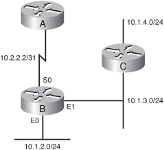
![]() Using this example network and configuration, consider which networks Router B will advertise to Router A when the various options of the eigrp stub command are also configured on Router B:
Using this example network and configuration, consider which networks Router B will advertise to Router A when the various options of the eigrp stub command are also configured on Router B:
- With the eigrp stub connected command, Router B will advertise only 10.1.2.0/24 to Router A. Notice that although 10.1.3.0/24 is also a connected network, it is not advertised to Router A because it is not advertised in a network command, and connected routes are not redistributed.
- With the eigrp stub summary command, Router B will advertise only 10.1.2.0/23, the summary route that is configured on the router, to Router A.
- With the eigrp stub static command, Router B will advertise only 10.1.4.0/24, the static route that is configured on the router, to Router A. (Note that the redistribute static command is configured on Router B.)
Note Without the static option, EIGRP will not send any static routes, including internal static routes that normally would be automatically redistributed. - With the eigrp stub receive-only command, Router B will not advertise anything to Router A.
- With the eigrp stub redistributed command, Router B will advertise only 10.1.4.0/24, the redistributed static route, to Router A.
Graceful Shutdown
![]() Graceful shutdown, implemented with the goodbye message feature, is designed to improve EIGRP network convergence.
Graceful shutdown, implemented with the goodbye message feature, is designed to improve EIGRP network convergence.
![]() In Figure 2-51, Router A is using Router B as the successor for several routes. Router C is the feasible successor for the same routes. Router B normally would not tell Router A if the EIGRP process on Router B was going down (for example, if Router B was being reconfigured). Router A would have to wait for its hold timer to expire before it would discover the change and react to it. Packets sent during this time would be lost.
In Figure 2-51, Router A is using Router B as the successor for several routes. Router C is the feasible successor for the same routes. Router B normally would not tell Router A if the EIGRP process on Router B was going down (for example, if Router B was being reconfigured). Router A would have to wait for its hold timer to expire before it would discover the change and react to it. Packets sent during this time would be lost.
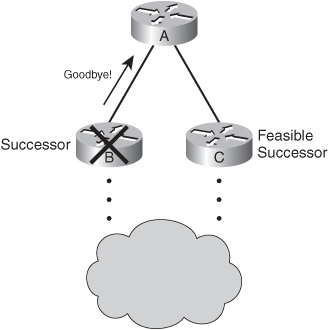
![]() With graceful shutdown, a goodbye message is broadcast when an EIGRP routing process is shut down, to inform adjacent peers about the impending topology change. This feature allows supporting EIGRP peers to synchronize and recalculate neighbor relationships more efficiently than would occur if the peers discovered the topology change after the hold timer expired.
With graceful shutdown, a goodbye message is broadcast when an EIGRP routing process is shut down, to inform adjacent peers about the impending topology change. This feature allows supporting EIGRP peers to synchronize and recalculate neighbor relationships more efficiently than would occur if the peers discovered the topology change after the hold timer expired.
![]() The goodbye message is supported in Cisco IOS Software Release 12.3(2), 12.3(3)B, and 12.3(2)T and later.
The goodbye message is supported in Cisco IOS Software Release 12.3(2), 12.3(3)B, and 12.3(2)T and later.
![]() Interestingly, goodbye messages are sent in hello packets. EIGRP sends an interface goodbye message with all K values set to 255 when taking down all peers on an interface.
Interestingly, goodbye messages are sent in hello packets. EIGRP sends an interface goodbye message with all K values set to 255 when taking down all peers on an interface.
![]() The following message is displayed by routers that support goodbye messages when one is received:
The following message is displayed by routers that support goodbye messages when one is received:
(Ethernet0/0) is down: Interface Goodbye received
![]() A Cisco router that runs a software release that does not support the goodbye message will misinterpret the message as a K value mismatch and therefore display the following message:
A Cisco router that runs a software release that does not support the goodbye message will misinterpret the message as a K value mismatch and therefore display the following message:
(Ethernet0/0) is down: K-value mismatch
| Note |
|
Summary
![]() In this chapter, you learned about Cisco’s EIGRP, an advanced distance vector routing protocol. The chapter focused on the following topics:
In this chapter, you learned about Cisco’s EIGRP, an advanced distance vector routing protocol. The chapter focused on the following topics:
- Features of EIGRP, including fast convergence, use of partial updates, multiple network layer support, use of multicast and unicast, VLSM support, seamless connectivity across all data link layer protocols and topologies, and sophisticated metrics.
- EIGRP’s underlying processes and technologies—neighbor discovery/recovery mechanism, RTP, DUAL finite-state machine, and protocol-dependent modules.
- EIGRP’s tables—neighbor table (containing all routers with which it has a neighbor relationship), topology table (containing all routes from all neighbors), and routing table (containing the best routes to each destination and used for forwarding packets).
- EIGRP terminology
- The advertised distance (the metric for an EIGRP neighbor router to reach the destination, which is the metric between the next-hop router and the destination), the feasible distance (the sum of the AD from the next-hop neighbor plus the cost between the local router and the next-hop router), the successor (a neighboring router that has a least-cost loop-free path to a destination, the lowest FD), and the feasible successor (a neighboring router that has a loop-free backup path to a destination).
- Passive routes, those not undergoing recomputation; active routes, those undergoing recomputation. Passive is the operational, stable state.
-
- The five EIGRP packet types: hello, update, query, reply, and acknowledgment. Updates, queries, and replies are sent reliably.
- EIGRP initial route discovery process, started by a router sending hello packets. Neighboring routers reply with update packets, which populate the router’s topology table. The router chooses the successor routes and offers them to the routing table.
- The DUAL process including selecting FSs. To qualify as an FS, a next-hop router must have an AD less than the FD of the current successor route for the particular network, to ensure a loop-free network.
- The EIGRP metric calculation, which defaults to bandwidth (the slowest bandwidth between the source and destination) plus delay (the cumulative interface delay along the path).
- Planning EIGRP implementations, including the IP addressing, network topology, and EIGRP traffic engineering. The list of tasks for each router in the network includes enabling the EIGRP routing protocol (with the correct autonomous system number), configuring the proper network statements, and optionally configuring the metric to appropriate interfaces.
- Basic EIGRP configuration commands
- router eigrp autonomous-system-number global configuration command
- network network-number [wildcard-mask] interface configuration command
- bandwidth kilobits interface configuration command
-
- Commands for verifying EIGRP operation
- show ip eigrp neighbors
- show ip route
- show ip route eigrp
- show ip protocols
- show ip eigrp interfaces
- show ip eigrp topology
- show ip eigrp traffic
- debug eigrp packets
- debug ip eigrp
- debug ip eigrp summary
- debug eigrp neighbors
-
- Using the passive-interface type number [default] router configuration command to prevent a routing protocol’s routing updates from being sent through the specified router interface. With EIGRP, hello messages are not sent out of the specified interface, so neighborships are not formed on that interface. However, the router will still advertise the network to its EIGRP neighbors.
- Creating a statically configured default route with the ip route 0.0.0.0 0.0.0.0 next-hop | interface global configuration command. Alternatively, any major network residing in the local routing table can become an EIGRP default route when used in the ip default-network network-number global configuration command.
- EIGRP summarization: EIGRP automatically summarizes on the major network boundary by default (in some IOS versions). To turn off automatic summarization, use the no auto-summary router configuration command. Use the ip summary-address eigrp as-number address mask [admin-distance] interface configuration command to manually create a summary route at an arbitrary bit boundary, as long as a more specific route exists in the routing table.
- EIGRP over Frame Relay, including
- An overview of Frame Relay, where PVCs are created by an SP and are identified by DLCIs, locally significant numbers between the router and the Frame Relay switch.
- EIGRP over a physical interface using Inverse ARP dynamic mapping, the default
- EIGRP over the physical interface using static maps with the frame-relay map protocol protocol-address dlci [broadcast] [ietf | cisco] [payload-compress {packet-by-packet | frf9 stac}] interface configuration command.
- Configuring subinterfaces with the interface serial number.subinterface-number {point-to-point | multipoint} command.
- Frame Relay multipoint subinterfaces, on which the IP address-to-DLCI mapping is done by either specifying the local DLCI value (using the frame-relay interface-dlci dlci command) and relying on Inverse ARP, or using manual IP address-to-DLCI mapping.
- Frame Relay point-to-point subinterfaces, on which the IP address-to-DLCI mapping is done by specifying the local DLCI value.
- Split horizon, which is disabled by default on most interfaces. Split horizon is enabled by default on Frame Relay multipoint interfaces. It can be disabled with the no ip split-horizon eigrp as-number command.
- The neighbor {ip-address | ipv6-address} interface-type interface-number router configuration command, used to define a neighboring EIGRP router. Instead of using multicast packets, EIGRP exchanges routing information with the specified neighbor using unicast packets.
-
- EIGRP over MPLS, including
- MPLS, which uses labels assigned to each packet at the edge of the network; MPLS nodes use the label to determine where to send the packet.
- A Layer 2 MPLS VPN, which provides a Layer 2 service across the backbone, where customer routers are connected together on the same IP subnet. A type of AToM, called EoMPLS may be used. Customer routers may also be connected to MPLS edge routers via VLAN subinterfaces; different subinterfaces in the PE routers are used to connect to different VLANs.
- A Layer 3 MPLS VPN, which provides a Layer 3 service across the backbone, where customer routers are connected to ISP edge routers, and on each side, a separate IP subnet is used. The CE routers see the PE routers as another customer router in the path. PE routers maintain separate routing tables for each customer.
-
- EIGRP load-balancing, including
- EIGRP equal-cost load balancing that distributes traffic over all interfaces with the same metric for the destination address.
- The maximum-paths maximum-path router configuration command, to specify up to 16 equally good routes be kept in the routing table. Set maximum-path to 1 to disable load balancing.
- EIGRP unequal-cost load balancing, across routes with different metrics, using the variance multiplier router configuration command and the traffic-share [balanced | min across-interfaces] router configuration command.
-
- EIGRP operation in WAN environments
- By default, EIGRP uses up to 50 percent of the bandwidth declared on an interface or subinterface. EIGRP uses the bandwidth of the link set by the bandwidth command, or the link’s default bandwidth if none is configured, when calculating how much bandwidth to use. The ip bandwidth-percent eigrp as-number percent interface configuration command changes the percentage.
- Configuring multipoint interfaces: Configure the bandwidth to represent the minimum CIR times the number of circuits. For a small number of very low-speed circuits, define the interfaces as point-to-point so that their bandwidth can be set to match the provisioned CIR.
-
- Configuring, verifying, and troubleshooting EIGRP MD5 authentication, including the following commands
- ip authentication mode eigrp autonomous-system md5 interface configuration command
- key chain name-of-chain global configuration command
- key key-id key-chain configuration command
- key-string key key-chain-key configuration command
- accept-lifetime start-time {infinite | end-time | duration seconds} key-chain-key configuration command
- send-lifetime start-time {infinite | end-time | duration seconds} key-chain-key configuration command
- ip authentication key-chain eigrp autonomous-system name-of-chain interface configuration command
- show ip eigrp neighbors
- show ip route
- show key chain
- debug eigrp packets
-
- EIGRP scalability factors, including the amount of information exchanged, the number of routers, the depth of the topology, and the number of alternative paths through the network.
- The SIA state: If an EIGRP router does not receive a reply to all the outstanding queries within 3 minutes (the default time) it goes into SIA state, and the router resets the neighbor relationships for the neighbors that failed to reply. Reasons for going into SIA include: router is too busy, the link between the routers is not good, or the link has a unidirectional failure.
- The Active Process Enhancement feature that adds SIA-Query and SIA-Reply to ensure that only appropriate neighbor relationships are reset.
- Limiting the query range to help reduce SIAs, which can be accomplished by
- Only announcing default routes to remote routers, which are configured to announce only their directly connected networks.
- Configuring route summarization using the ip summary-address eigrp command on the outbound interfaces of the appropriate routers
- Route and interface packet filtering.
- Configuring the remote routers as stub EIGRP routers so that they will not be queried, using the eigrp stub [receive-only | connected | static | summary | redistributed] router configuration command.
- Using both EIGRP route summarization and EIGRP stub features is recommended, to provide the best scalability.
-
- Graceful shutdown, which broadcasts a goodbye message (in a hello packet, with all K values set to 255) when an EIGRP routing process is shut down, to inform neighbors.
0 comments
Post a Comment