
Reviewing IP Routing Principles
![]() After the design and implementation plan are complete, the implementation begins. This typically involves routing changes; routing is, of course, the focus of this book.
After the design and implementation plan are complete, the implementation begins. This typically involves routing changes; routing is, of course, the focus of this book.
| Note |
|
![]() This section reviews IP routing, including static and dynamic routing characteristics, and on-demand routing (ODR). Routing protocol characteristics are explored, including distance vector, link-state, and advanced distance vector (also called hybrid) routing; classful and classless routing; and manual and automatic route summarization across network boundaries. Characteristics and configuration of RIP are described. A discussion of how Cisco routers populate their routing tables includes administrative distance, routing metrics, and the criteria routers use for inserting routes into the IP routing table. Comparisons of IP routing protocols are shown. The section ends with a discussion of routing protocols within the Enterprise Composite Network Model.
This section reviews IP routing, including static and dynamic routing characteristics, and on-demand routing (ODR). Routing protocol characteristics are explored, including distance vector, link-state, and advanced distance vector (also called hybrid) routing; classful and classless routing; and manual and automatic route summarization across network boundaries. Characteristics and configuration of RIP are described. A discussion of how Cisco routers populate their routing tables includes administrative distance, routing metrics, and the criteria routers use for inserting routes into the IP routing table. Comparisons of IP routing protocols are shown. The section ends with a discussion of routing protocols within the Enterprise Composite Network Model.
 IP Routing Overview
![]() Routers forward packets toward destination networks. To forward the packets, routers must know about these remote networks and determine the best way to reach them. This section addresses the ways in which routers learn about networks and how routers can incorporate static and dynamic routes.
Routers forward packets toward destination networks. To forward the packets, routers must know about these remote networks and determine the best way to reach them. This section addresses the ways in which routers learn about networks and how routers can incorporate static and dynamic routes.
![]() Routers must be aware of destination networks to be able to forward packets to them. A router knows about the networks directly attached to its interfaces; it calculates the subnet or network number of an interface by using the address and subnet mask configured on that interface. For networks not directly connected to one of its interfaces, however, the router must rely on outside information. A router can be made aware of remote networks in two ways:
Routers must be aware of destination networks to be able to forward packets to them. A router knows about the networks directly attached to its interfaces; it calculates the subnet or network number of an interface by using the address and subnet mask configured on that interface. For networks not directly connected to one of its interfaces, however, the router must rely on outside information. A router can be made aware of remote networks in two ways:
- Static routing— An administrator can manually configure the information.
- Dynamic routing— A router can learn from other routers.
![]() A routing table can contain both static and dynamically recognized routes. Network administrators can use static routing, dynamic routing, or a combination of both.
A routing table can contain both static and dynamically recognized routes. Network administrators can use static routing, dynamic routing, or a combination of both.
Principles of Static Routing
![]() This section explains the situations in which static routes are the most appropriate to use.
This section explains the situations in which static routes are the most appropriate to use.
![]() A static route can be used in the following circumstances:
A static route can be used in the following circumstances:
- When it is undesirable to have dynamic routing updates forwarded across slow bandwidth links, such as a dialup link.
- When the administrator needs total control over the routes used by the router.
- When a backup to a dynamically recognized route is necessary.
- When it is necessary to reach a network accessible by only one path (a stub network). For example, in Figure 1-9, there is only one way for Router A to reach the 10.2.0.0/16 network on Router B. The administrator can configure a static route on Router A to reach the 10.2.0.0/16 network via its Serial 0/0/0 interface.
- When a router connects to its ISP and needs to have only a default route pointing toward the ISP router, rather than learning many routes from the ISP.
- When a router is underpowered and does not have the CPU or memory resources necessary to handle a dynamic routing protocol.


![]() A perfect use for static routing is a hub-and-spoke design, with all remote sites defaulting back to the central site (the hub) and the one or two routers at the central site having a static route for all subnets at each remote site. However, without proper design, as the network grows into hundreds of routers, with each router having numerous subnets, the number of static routes on each router also increases. Each time a new subnet or router is added, an administrator must add a static route to the new networks on several routers. The administrative burden to maintain this network can become excessive, making dynamic routing a better choice.
A perfect use for static routing is a hub-and-spoke design, with all remote sites defaulting back to the central site (the hub) and the one or two routers at the central site having a static route for all subnets at each remote site. However, without proper design, as the network grows into hundreds of routers, with each router having numerous subnets, the number of static routes on each router also increases. Each time a new subnet or router is added, an administrator must add a static route to the new networks on several routers. The administrative burden to maintain this network can become excessive, making dynamic routing a better choice.
![]() Another drawback of static routing is that when a topology change occurs on the internetwork, an administrator might have to reroute traffic by configuring new static routes around the problem area. In contrast, with dynamic routing, the routers must learn the new topology. The routers share information with each other and their routing processes automatically discover whether any alternative routes exist and reroute without administrator intervention. Because the routers mutually develop an independent agreement of what the new topology is, they are said to converge on what the new routes should be. A network is converged when routing tables on all routers in the network are synchronized and contain a route to all destination networks. Convergence time is the time it takes for all routers in a network to agree on the new topology. Dynamic routing provides faster convergence.
Another drawback of static routing is that when a topology change occurs on the internetwork, an administrator might have to reroute traffic by configuring new static routes around the problem area. In contrast, with dynamic routing, the routers must learn the new topology. The routers share information with each other and their routing processes automatically discover whether any alternative routes exist and reroute without administrator intervention. Because the routers mutually develop an independent agreement of what the new topology is, they are said to converge on what the new routes should be. A network is converged when routing tables on all routers in the network are synchronized and contain a route to all destination networks. Convergence time is the time it takes for all routers in a network to agree on the new topology. Dynamic routing provides faster convergence.
Configuring a Static Route
![]() Use the ip route prefix mask {address | interface [address]} [dhcp] [distance] [name next-hop-name] [permanent| track number] [tag tag] global configuration command to create static routes. The parameters of this command are explained in Table 1-5.
Use the ip route prefix mask {address | interface [address]} [dhcp] [distance] [name next-hop-name] [permanent| track number] [tag tag] global configuration command to create static routes. The parameters of this command are explained in Table 1-5.
|
|
|
|---|---|
|
|
|
|
|
|
|
|
|
|
|
|
|
|
|
|
|
|
|
|
|
|
|
|
|
|
|
| Note |
|
![]() If no dynamic routing protocol is used on a link connecting two routers, such as in Figure 1-9, a static route must be configured on the routers on both sides of the link. Otherwise, the remote router will not know how to return the packet to its originator located on the other network; there will be only one-way communication.
If no dynamic routing protocol is used on a link connecting two routers, such as in Figure 1-9, a static route must be configured on the routers on both sides of the link. Otherwise, the remote router will not know how to return the packet to its originator located on the other network; there will be only one-way communication.
![]() While configuring a static route, you must specify either a next-hop IP address or an exit interface to notify the router which direction to send traffic. Figure 1-9 shows both configurations. Router A recognizes the directly connected networks 172.16.1.0 and 10.1.1.0. It needs a route to the remote network 10.2.0.0. Router B knows about the directly connected networks 10.2.0.0 and 10.1.1.0; it needs a route to the remote network 172.16.1.0. Notice that on Router B, the next-hop IP address of the Router A serial interface has been used. On Router A, however, the ip route command specifies its own Serial 0/0/0 interface as the exit interface. If a next-hop IP address is used, it should be the IP address of the interface of the router on the other end of the link. If an exit interface is used, the local router sends data out of the specified interface to the router on the other end of its attached link. When an exit interface is specified, the router considers this to be similar to a directly connected route (as detailed in the Note following Table 1-6 later in the “Administrative Distance” section).
While configuring a static route, you must specify either a next-hop IP address or an exit interface to notify the router which direction to send traffic. Figure 1-9 shows both configurations. Router A recognizes the directly connected networks 172.16.1.0 and 10.1.1.0. It needs a route to the remote network 10.2.0.0. Router B knows about the directly connected networks 10.2.0.0 and 10.1.1.0; it needs a route to the remote network 172.16.1.0. Notice that on Router B, the next-hop IP address of the Router A serial interface has been used. On Router A, however, the ip route command specifies its own Serial 0/0/0 interface as the exit interface. If a next-hop IP address is used, it should be the IP address of the interface of the router on the other end of the link. If an exit interface is used, the local router sends data out of the specified interface to the router on the other end of its attached link. When an exit interface is specified, the router considers this to be similar to a directly connected route (as detailed in the Note following Table 1-6 later in the “Administrative Distance” section).
Configuring a Static Default Route
![]() In some circumstances, a router does not need to recognize the details of remote networks. The router is configured to send all traffic, or all traffic for which there is not a more specific entry in the routing table, in a particular direction; this is known as a default route. Default routes are either dynamically advertised using routing protocols or statically configured.
In some circumstances, a router does not need to recognize the details of remote networks. The router is configured to send all traffic, or all traffic for which there is not a more specific entry in the routing table, in a particular direction; this is known as a default route. Default routes are either dynamically advertised using routing protocols or statically configured.
![]() To create a static default route, use the normal ip route command, but with the destination network (the prefix in the command syntax) and its subnet mask (the mask in the command syntax) both set to 0.0.0.0. This address is a type of wildcard designation; any destination network will match. Because the router tries to match the longest common bit pattern, a network listed in the routing table is used before the default route. If the destination network is not listed in the routing table, the default route is used.
To create a static default route, use the normal ip route command, but with the destination network (the prefix in the command syntax) and its subnet mask (the mask in the command syntax) both set to 0.0.0.0. This address is a type of wildcard designation; any destination network will match. Because the router tries to match the longest common bit pattern, a network listed in the routing table is used before the default route. If the destination network is not listed in the routing table, the default route is used.
| Note |
|
![]() In Figure 1-10, on Router A, the static route to the 10.2.0.0 network has been replaced with a static default route pointing to Router B. On Router B, a static default route has been added, pointing to its ISP. Traffic from a device on the Router A 172.16.1.0 network bound for a network on the Internet is sent to Router B. Router B recognizes that the destination network does not match any specific entries in its routing table and sends that traffic to the ISP. It is then the ISP’s responsibility to route that traffic to its destination.
In Figure 1-10, on Router A, the static route to the 10.2.0.0 network has been replaced with a static default route pointing to Router B. On Router B, a static default route has been added, pointing to its ISP. Traffic from a device on the Router A 172.16.1.0 network bound for a network on the Internet is sent to Router B. Router B recognizes that the destination network does not match any specific entries in its routing table and sends that traffic to the ISP. It is then the ISP’s responsibility to route that traffic to its destination.


![]() In Figure 1-10, to reach the 172.16.1.0/24 network, Router B still needs a static route pointing out its S0/0/0 interface.
In Figure 1-10, to reach the 172.16.1.0/24 network, Router B still needs a static route pointing out its S0/0/0 interface.
![]() Entering the show ip route command on Router A in Figure 1-10 returns the information shown in Example 1-1.
Entering the show ip route command on Router A in Figure 1-10 returns the information shown in Example 1-1.
Principles of Dynamic Routing
![]() Dynamic routing allows the network to adjust to changes in the topology automatically, without administrator involvement. This section describes dynamic routing principles.
Dynamic routing allows the network to adjust to changes in the topology automatically, without administrator involvement. This section describes dynamic routing principles.
![]() A static route cannot respond dynamically to changes in the network. If a link fails, the static route is no longer valid if it is configured to use that failed link, so a new static route must be configured. If a new router or new link is added, that information must also be configured on every router in the network. In an unstable network, or one that has more than a few routes, these changes can lead to considerable work for network administrators. It can also take a long time for every router in the network to receive the correct information. In situations such as these, it might be better to have the routers receive information about networks and links from each other using a dynamic routing protocol.
A static route cannot respond dynamically to changes in the network. If a link fails, the static route is no longer valid if it is configured to use that failed link, so a new static route must be configured. If a new router or new link is added, that information must also be configured on every router in the network. In an unstable network, or one that has more than a few routes, these changes can lead to considerable work for network administrators. It can also take a long time for every router in the network to receive the correct information. In situations such as these, it might be better to have the routers receive information about networks and links from each other using a dynamic routing protocol.
![]() When using a dynamic routing protocol, the administrator configures the routing protocol on each router, as shown in Figure 1-11. The routers then exchange information about the reachable networks and the state of each network. Routers exchange information only with other routers running the same routing protocol. When the network topology changes, the new information is dynamically propagated throughout the network, and each router updates its routing table to reflect the changes. The following are some examples of dynamic routing protocols:
When using a dynamic routing protocol, the administrator configures the routing protocol on each router, as shown in Figure 1-11. The routers then exchange information about the reachable networks and the state of each network. Routers exchange information only with other routers running the same routing protocol. When the network topology changes, the new information is dynamically propagated throughout the network, and each router updates its routing table to reflect the changes. The following are some examples of dynamic routing protocols:


- RIP (versions 1 and 2)
- EIGRP
- IS-IS
- OSPF
- BGP
![]() The information exchanged by routers includes the metric to each destination (this value is sometimes called the distance or cost). A metric is a value that routing protocols use to measure paths to a destination.
The information exchanged by routers includes the metric to each destination (this value is sometimes called the distance or cost). A metric is a value that routing protocols use to measure paths to a destination.
![]() Different routing protocols base their metric on different measurements, including hop count, interface speed, or more-complex metrics. Most routing protocols maintain databases containing all the networks that the routing protocol recognizes, all the paths to each network, and the metric of each of these paths. If a routing protocol recognizes more than one way to reach a network, it compares the metric for each different path and chooses the path with the lowest metric. If multiple paths have the same metric, a maximum of 16 can be installed in the routing table, and the router can perform load balancing between them. EIGRP can also perform load balancing between unequal-cost paths.
Different routing protocols base their metric on different measurements, including hop count, interface speed, or more-complex metrics. Most routing protocols maintain databases containing all the networks that the routing protocol recognizes, all the paths to each network, and the metric of each of these paths. If a routing protocol recognizes more than one way to reach a network, it compares the metric for each different path and chooses the path with the lowest metric. If multiple paths have the same metric, a maximum of 16 can be installed in the routing table, and the router can perform load balancing between them. EIGRP can also perform load balancing between unequal-cost paths.
| Note |
|
![]() To configure an IP dynamic routing protocol, use the router protocol global configuration command. Protocols other than RIP also require specification of either an autonomous system or a process number. You also need the network command under the router configuration mode of all routing protocols except IS-IS and BGP.
To configure an IP dynamic routing protocol, use the router protocol global configuration command. Protocols other than RIP also require specification of either an autonomous system or a process number. You also need the network command under the router configuration mode of all routing protocols except IS-IS and BGP.
![]() For RIP, EIGRP, and OSPF, the network command tells the router which interfaces are participating in that routing protocol. Any interface that has an IP address that falls within the range specified in the network statement is considered active for that protocol. In other words, the router sends updates from the specified interfaces and expects to receive updates from the same interfaces. Some protocols look for neighbors by sending hello packets out those interfaces. Thus, because a network statement identifies interfaces on the local router, it is configured only for directly connected networks. A router also originates advertisements for the networks connected to the specified interfaces.
For RIP, EIGRP, and OSPF, the network command tells the router which interfaces are participating in that routing protocol. Any interface that has an IP address that falls within the range specified in the network statement is considered active for that protocol. In other words, the router sends updates from the specified interfaces and expects to receive updates from the same interfaces. Some protocols look for neighbors by sending hello packets out those interfaces. Thus, because a network statement identifies interfaces on the local router, it is configured only for directly connected networks. A router also originates advertisements for the networks connected to the specified interfaces.
![]() RIP allows only major network numbers (Class A, B, or C network numbers) to be specified in the network command. EIGRP and OSPF permit exact specification of interfaces with a combination of a subnet or interface address and a wildcard mask.
RIP allows only major network numbers (Class A, B, or C network numbers) to be specified in the network command. EIGRP and OSPF permit exact specification of interfaces with a combination of a subnet or interface address and a wildcard mask.
![]() The network statement functions differently in BGP. BGP requires its neighbors to be statically configured. The network statement in BGP tells the router to originate an advertisement for that network. Without a network statement, BGP passes along advertisements it receives from other routers, but it does not originate any network advertisements itself. In BGP, the network listed in the network statement does not have to be directly connected, because it does not identify interfaces on the router as it does in other protocols. (This process is explained in detail in Chapter 6, “Implementing a Border Gateway Protocol Solution for ISP Connectivity.”)
The network statement functions differently in BGP. BGP requires its neighbors to be statically configured. The network statement in BGP tells the router to originate an advertisement for that network. Without a network statement, BGP passes along advertisements it receives from other routers, but it does not originate any network advertisements itself. In BGP, the network listed in the network statement does not have to be directly connected, because it does not identify interfaces on the router as it does in other protocols. (This process is explained in detail in Chapter 6, “Implementing a Border Gateway Protocol Solution for ISP Connectivity.”)
![]() Integrated IS-IS does not use the network statement. Instead, interfaces participating in the IS-IS routing process are identified under interface configuration mode. (OSPF also permits the interfaces to be specified this way, as an alternative to using the network command.)
Integrated IS-IS does not use the network statement. Instead, interfaces participating in the IS-IS routing process are identified under interface configuration mode. (OSPF also permits the interfaces to be specified this way, as an alternative to using the network command.)
![]() Example 1-2 shows the configuration of the routers in Figure 1-11. Both Routers A and B are configured with RIP. Router A has two directly attached networks and RIP is used to advertise to neighbors on both of those interfaces. Therefore, network statements are configured for both the 172.16.0.0 network and the 10.0.0.0 network. Router A sends RIP packets out interfaces Fa0/0 and S0/0/0, advertising the networks that are attached to those interfaces.
Example 1-2 shows the configuration of the routers in Figure 1-11. Both Routers A and B are configured with RIP. Router A has two directly attached networks and RIP is used to advertise to neighbors on both of those interfaces. Therefore, network statements are configured for both the 172.16.0.0 network and the 10.0.0.0 network. Router A sends RIP packets out interfaces Fa0/0 and S0/0/0, advertising the networks that are attached to those interfaces.
routerA(config-router)#network 172.16.0.0
routerA(config-router)#network 10.0.0.0
routerB(config)#ip route 0.0.0.0 0.0.0.0 Serial0/0/1
routerB(config)#router rip
routerB(config-router)#network 10.0.0.0
![]() Router B also has two directly attached networks. However, Router B wants only the network it shares with Router A to participate in RIP. Therefore, a network statement is configured only for the 10.0.0.0 network. As explained earlier, with RIP, only the major network number is actually used in the network command. Router B also has a static default route pointing toward its ISP to reach other networks. Router B sends RIP packets out its interface S0/0/0, but not out its interface S0/0/1. It does not advertise the 192.168.1.0 network attached to S0/0/1 or the static default route unless specifically configured to do so.
Router B also has two directly attached networks. However, Router B wants only the network it shares with Router A to participate in RIP. Therefore, a network statement is configured only for the 10.0.0.0 network. As explained earlier, with RIP, only the major network number is actually used in the network command. Router B also has a static default route pointing toward its ISP to reach other networks. Router B sends RIP packets out its interface S0/0/0, but not out its interface S0/0/1. It does not advertise the 192.168.1.0 network attached to S0/0/1 or the static default route unless specifically configured to do so.
Principles of On-Demand Routing
![]() A drawback of static routes is that they must be manually configured and updated when the network topology changes. A drawback of dynamic routing protocols is that they use network bandwidth and router resources. In a hub-and-spoke network with hundreds of spokes, both the configuration needed for static routes and the resource usage of dynamic routing can be considerable.
A drawback of static routes is that they must be manually configured and updated when the network topology changes. A drawback of dynamic routing protocols is that they use network bandwidth and router resources. In a hub-and-spoke network with hundreds of spokes, both the configuration needed for static routes and the resource usage of dynamic routing can be considerable.
![]() There is a third option: ODR. ODR uses the Cisco Discovery Protocol (CDP) to carry network information between spoke (stub) routers and the hub router. ODR provides IP routing information with minimal overhead compared to a dynamic routing protocol and requires less manual configuration than static routes.
There is a third option: ODR. ODR uses the Cisco Discovery Protocol (CDP) to carry network information between spoke (stub) routers and the hub router. ODR provides IP routing information with minimal overhead compared to a dynamic routing protocol and requires less manual configuration than static routes.
![]() ODR is applicable in a hub-and-spoke topology only. In this type of topology, each spoke router is adjacent only to the hub. Another name for a spoke router is stub router. The stub router may have some LAN networks connected to it and typically has a WAN connection to the hub router. The hub router needs to recognize the networks connected to each spoke, but the spoke routers need only a default route pointing to the hub router.
ODR is applicable in a hub-and-spoke topology only. In this type of topology, each spoke router is adjacent only to the hub. Another name for a spoke router is stub router. The stub router may have some LAN networks connected to it and typically has a WAN connection to the hub router. The hub router needs to recognize the networks connected to each spoke, but the spoke routers need only a default route pointing to the hub router.
![]() When ODR is configured, the stub routers use CDP to send IP prefix information to the hub router. Stub routers send prefix information for all their directly connected networks. ODR reports the subnet mask, so it allows different subnets within the same major network to have different subnet masks. This is known as variable-length subnet masking (VLSM) and is described in detail in Appendix B.
When ODR is configured, the stub routers use CDP to send IP prefix information to the hub router. Stub routers send prefix information for all their directly connected networks. ODR reports the subnet mask, so it allows different subnets within the same major network to have different subnet masks. This is known as variable-length subnet masking (VLSM) and is described in detail in Appendix B.
![]() The hub router, in turn, sends a default route to the spokes that points back to itself. It installs the stub networks reported by ODR in its routing table and can be configured to redistribute these routes into a dynamic routing protocol. For a next-hop address, the hub router uses the IP address of the spoke router as reported to it by CDP.
The hub router, in turn, sends a default route to the spokes that points back to itself. It installs the stub networks reported by ODR in its routing table and can be configured to redistribute these routes into a dynamic routing protocol. For a next-hop address, the hub router uses the IP address of the spoke router as reported to it by CDP.
![]() ODR is not a true routing protocol because the information exchanged is limited to IP prefixes and a default route. ODR reports no metric information; the hub router uses a hop count of 1 as the metric for all routes reported via ODR. However, by using ODR, routing information for stub networks can be obtained dynamically without the overhead of a dynamic routing protocol, and default routes can be provided to the stub routers without manual configuration.
ODR is not a true routing protocol because the information exchanged is limited to IP prefixes and a default route. ODR reports no metric information; the hub router uses a hop count of 1 as the metric for all routes reported via ODR. However, by using ODR, routing information for stub networks can be obtained dynamically without the overhead of a dynamic routing protocol, and default routes can be provided to the stub routers without manual configuration.
Configuring ODR
![]() ODR is configured on the hub router using the router odr global configuration command.
ODR is configured on the hub router using the router odr global configuration command.
![]() On the stub router, there must be no IP routing protocol configured. In fact, from the standpoint of ODR, a router is automatically considered a stub when no IP routing protocols have been configured. Figure 1-12 shows a hub-and-spoke topology.
On the stub router, there must be no IP routing protocol configured. In fact, from the standpoint of ODR, a router is automatically considered a stub when no IP routing protocols have been configured. Figure 1-12 shows a hub-and-spoke topology.


![]() ODR can also be tuned with optional commands, including using a distribute list to control the network information that is recognized through ODR, and adjusting the ODR timers with the timers basic router configuration command.
ODR can also be tuned with optional commands, including using a distribute list to control the network information that is recognized through ODR, and adjusting the ODR timers with the timers basic router configuration command.
![]() ODR relies on CDP to carry the information between the hub router and the spoke routers. Therefore, CDP must be enabled on the links between the hub router and the spoke routers. Cisco routers by default have CDP enabled both globally and per interface on most interfaces. However, on some WAN links, such as ATM, CDP must be explicitly enabled.
ODR relies on CDP to carry the information between the hub router and the spoke routers. Therefore, CDP must be enabled on the links between the hub router and the spoke routers. Cisco routers by default have CDP enabled both globally and per interface on most interfaces. However, on some WAN links, such as ATM, CDP must be explicitly enabled.
![]() CDP updates are sent as multicasts. CDP uses Subnetwork Access Protocol (SNAP) frames, so it runs on all media that support SNAP.
CDP updates are sent as multicasts. CDP uses Subnetwork Access Protocol (SNAP) frames, so it runs on all media that support SNAP.
![]() CDP updates are sent every 60 seconds by default. This setting might be too infrequent in rapidly changing networks or too often in stable ones. You can adjust the timers with the cdp timer global configuration command. You can verify CDP settings by using the show cdp interface command.
CDP updates are sent every 60 seconds by default. This setting might be too infrequent in rapidly changing networks or too often in stable ones. You can adjust the timers with the cdp timer global configuration command. You can verify CDP settings by using the show cdp interface command.
![]() As soon as ODR is configured and running, routes from the stub routers are identified in the hub router’s routing table with an o character, as shown in Example 1-3. Notice in the example that the metric is 1 (hop), and the administrative distance for ODR is 160. (Administrative distance is described in the “Administrative Distance” section, later in this chapter.) Also, do not confuse the o character of ODR routes with the O character of OSPF routes.
As soon as ODR is configured and running, routes from the stub routers are identified in the hub router’s routing table with an o character, as shown in Example 1-3. Notice in the example that the metric is 1 (hop), and the administrative distance for ODR is 160. (Administrative distance is described in the “Administrative Distance” section, later in this chapter.) Also, do not confuse the o character of ODR routes with the O character of OSPF routes.
Characteristics of Routing Protocols
![]() Routing protocols can be classified into different categories such as distance vector, link-state, or advanced distance vector. IP routing protocols can also be classified as either classful or classless. These characteristics are explored in this section.
Routing protocols can be classified into different categories such as distance vector, link-state, or advanced distance vector. IP routing protocols can also be classified as either classful or classless. These characteristics are explored in this section.
Distance Vector, Link-State, and Advanced Distance Vector Routing Protocols
![]() When a network is using a distance vector routing protocol, all the routers periodically send their routing tables (or a portion of their tables) to only their neighboring routers. The routers then use the received information to determine whether any changes need to be made to their own routing table (for example, if a better way to a specific network is now available). This process repeats periodically.
When a network is using a distance vector routing protocol, all the routers periodically send their routing tables (or a portion of their tables) to only their neighboring routers. The routers then use the received information to determine whether any changes need to be made to their own routing table (for example, if a better way to a specific network is now available). This process repeats periodically.
![]() In contrast, when a network is using a link-state routing protocol, each of the routers sends the state of its own interfaces (its links) to all other routers (or to all routers in a part of the network, known as an area) only when there is a change. Each router uses the received information to recalculate the best path to each network and then saves this information in its routing table.
In contrast, when a network is using a link-state routing protocol, each of the routers sends the state of its own interfaces (its links) to all other routers (or to all routers in a part of the network, known as an area) only when there is a change. Each router uses the received information to recalculate the best path to each network and then saves this information in its routing table.
![]() As its name suggests, a hybrid or advanced distance vector protocol has characteristics of both distance vector and link-state protocols. These protocols send only changed information when there is a change (similar to link-state protocols) but only to neighboring routers (similar to distance vector protocols).
As its name suggests, a hybrid or advanced distance vector protocol has characteristics of both distance vector and link-state protocols. These protocols send only changed information when there is a change (similar to link-state protocols) but only to neighboring routers (similar to distance vector protocols).
Classful Routing Protocol Concepts
![]() IP routing protocols can be categorized as classful or classless:
IP routing protocols can be categorized as classful or classless:
- Routing updates sent by a classful routing protocol do not include the subnet mask. RIP Version 1 (RIPv1) is a classful routing protocol.
- Routing updates sent by a classless routing protocol include the subnet mask. RIP Version 2 (RIPv2), EIGRP, OSPF, IS-IS, and BGP are classless routing protocols. Most modern networks use classless protocols.
Classful Routing Protocol Behavior
![]() When classful protocols were originally developed, networks were very different from those used now. The best modem speed was 300 bps, the largest WAN line was 56 kbps, router memory was less than 640 KB, and processors were running in the KHz range. Routing updates had to be small enough not to monopolize the WAN link bandwidth. In addition, routers did not have the resources to maintain current information about every subnet.
When classful protocols were originally developed, networks were very different from those used now. The best modem speed was 300 bps, the largest WAN line was 56 kbps, router memory was less than 640 KB, and processors were running in the KHz range. Routing updates had to be small enough not to monopolize the WAN link bandwidth. In addition, routers did not have the resources to maintain current information about every subnet.
![]() A classful routing protocol does not include subnet mask information in its routing updates. Because no subnet mask information is known, when a classful router receives routing updates, the router makes assumptions about the subnet mask being used by the networks listed in the update, based on IP address class.
A classful routing protocol does not include subnet mask information in its routing updates. Because no subnet mask information is known, when a classful router receives routing updates, the router makes assumptions about the subnet mask being used by the networks listed in the update, based on IP address class.
![]() Routers send update packets from their interfaces to other connected routers. A router sends the entire subnet address in the update when an update packet involves a subnet of the same classful network as the IP address of the transmitting interface. The receiving router then assumes that the mask of the subnet in the update (from the sending router) is the same as the mask on the receiving interface. For example, if Router A sends an update about 10.1.0.0 to Router B, and Router A and B are connected by the 10.2.0.0/16 subnet, Router B assumes that the mask for the 10.1.0.0 subnet is /16, the same mask that is on the interface that receives the update. If the subnet in the update actually has a different subnet mask, the receiving router will have incorrect information in its routing table. Therefore, when using a classful routing protocol, it is important to use the same subnet mask on all subnets belonging to the same classful network; in other words, classful routing protocols do not support VLSM.
Routers send update packets from their interfaces to other connected routers. A router sends the entire subnet address in the update when an update packet involves a subnet of the same classful network as the IP address of the transmitting interface. The receiving router then assumes that the mask of the subnet in the update (from the sending router) is the same as the mask on the receiving interface. For example, if Router A sends an update about 10.1.0.0 to Router B, and Router A and B are connected by the 10.2.0.0/16 subnet, Router B assumes that the mask for the 10.1.0.0 subnet is /16, the same mask that is on the interface that receives the update. If the subnet in the update actually has a different subnet mask, the receiving router will have incorrect information in its routing table. Therefore, when using a classful routing protocol, it is important to use the same subnet mask on all subnets belonging to the same classful network; in other words, classful routing protocols do not support VLSM.
![]() When a router that is using a classful routing protocol needs to send an update about a subnet of a network across an interface belonging to a different network, the router assumes that the remote router will use the default subnet mask for that class of IP address. Therefore, when the router sends the update, it does not include the subnet information; the update packet contains only the major (classful) network information. This process is called autosummarization across the network boundary; the router sends a summary of all the subnets in that network by sending only the major network information. Classful routing protocols automatically create a classful summary route at major network boundaries. Classful routing protocols do not allow summarization at other points within the major network address space.
When a router that is using a classful routing protocol needs to send an update about a subnet of a network across an interface belonging to a different network, the router assumes that the remote router will use the default subnet mask for that class of IP address. Therefore, when the router sends the update, it does not include the subnet information; the update packet contains only the major (classful) network information. This process is called autosummarization across the network boundary; the router sends a summary of all the subnets in that network by sending only the major network information. Classful routing protocols automatically create a classful summary route at major network boundaries. Classful routing protocols do not allow summarization at other points within the major network address space.
![]() The router that receives the update behaves in a similar fashion. When an update contains information about a different classful network than the one in use on its interface, the router applies the default classful mask to that update. The router must assume what the subnet mask is because the update does not contain subnet mask information.
The router that receives the update behaves in a similar fashion. When an update contains information about a different classful network than the one in use on its interface, the router applies the default classful mask to that update. The router must assume what the subnet mask is because the update does not contain subnet mask information.
![]() In Figure 1-13, Router A advertises the 10.1.0.0 subnet to Router B because the interface connecting them belongs to the same major classful 10.0.0.0 network. When Router B receives the update packet, it assumes that the 10.1.0.0 subnet uses the same 16-bit mask as the one used on its 10.2.0.0 subnet.
In Figure 1-13, Router A advertises the 10.1.0.0 subnet to Router B because the interface connecting them belongs to the same major classful 10.0.0.0 network. When Router B receives the update packet, it assumes that the 10.1.0.0 subnet uses the same 16-bit mask as the one used on its 10.2.0.0 subnet.


![]() Router C advertises the 172.16.1.0 subnet to Router B because the interface connecting them belongs to the same major classful 172.16.0.0 network. Therefore, Router B’s routing table has information about all the subnets that are in use in the network.
Router C advertises the 172.16.1.0 subnet to Router B because the interface connecting them belongs to the same major classful 172.16.0.0 network. Therefore, Router B’s routing table has information about all the subnets that are in use in the network.
![]() However, Router B summarizes the 172.16.1.0 and 172.16.2.0 subnets to 172.16.0.0 before sending them to Router A. Therefore, Router A’s routing table contains only summary information about the 172.16.0.0 network.
However, Router B summarizes the 172.16.1.0 and 172.16.2.0 subnets to 172.16.0.0 before sending them to Router A. Therefore, Router A’s routing table contains only summary information about the 172.16.0.0 network.
![]() Similarly, Router B summarizes the 10.1.0.0 and 10.2.0.0 subnets to 10.0.0.0 before sending the routing information to Router C. This summarization occurs because the update crosses a major network boundary. The update goes from a subnet of network 10.0.0.0, subnet 10.2.0.0, to a subnet of another major network, network 172.16.0.0. Router C’s routing table contains only summary information about the 10.0.0.0 network.
Similarly, Router B summarizes the 10.1.0.0 and 10.2.0.0 subnets to 10.0.0.0 before sending the routing information to Router C. This summarization occurs because the update crosses a major network boundary. The update goes from a subnet of network 10.0.0.0, subnet 10.2.0.0, to a subnet of another major network, network 172.16.0.0. Router C’s routing table contains only summary information about the 10.0.0.0 network.
Summarizing Routes in a Network with Discontiguous Subnets
![]() Discontiguous subnets are subnets of the same major network that are separated by a different major network.
Discontiguous subnets are subnets of the same major network that are separated by a different major network.
![]() Recall that classful protocols automatically summarize at network boundaries, which means that the following:
Recall that classful protocols automatically summarize at network boundaries, which means that the following:
- Discontiguous subnets are not visible to each other.
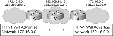
![]() In Figure 1-14, Routers A and B do not advertise the 172.16.5.0 255.255.255.0 and 172.16.6.0 255.255.255.0 subnets to Router C because RIPv1 cannot advertise subnets across a different major network; both Router A and Router B advertise 172.16.0.0 to Router C. This leads to confusion when routing across network 192.168.14.16/28. Router C, for example, receives routes about 172.16.0.0 from two different directions; it therefore might make an incorrect routing decision.
In Figure 1-14, Routers A and B do not advertise the 172.16.5.0 255.255.255.0 and 172.16.6.0 255.255.255.0 subnets to Router C because RIPv1 cannot advertise subnets across a different major network; both Router A and Router B advertise 172.16.0.0 to Router C. This leads to confusion when routing across network 192.168.14.16/28. Router C, for example, receives routes about 172.16.0.0 from two different directions; it therefore might make an incorrect routing decision.
![]() Although they are classless protocols, RIPv2 and EIGRP also automatically summarize at network boundaries by default. However, this feature can be turned off in RIPv2 and EIGRP. It cannot be turned off for RIPv1.
Although they are classless protocols, RIPv2 and EIGRP also automatically summarize at network boundaries by default. However, this feature can be turned off in RIPv2 and EIGRP. It cannot be turned off for RIPv1.
![]() You can resolve this situation by using RIPv2, OSPF, IS-IS, or EIGRP and not using summarization, so that the subnet routes will be advertised with their actual subnet masks.
You can resolve this situation by using RIPv2, OSPF, IS-IS, or EIGRP and not using summarization, so that the subnet routes will be advertised with their actual subnet masks.
| Note |
|
The ip classless Command
![]() The behavior of a classful routing protocol changes when the ip classless global configuration command is used.
The behavior of a classful routing protocol changes when the ip classless global configuration command is used.
| Note |
|
![]() When you are running a classful protocol (RIPv1), ip classless must be enabled if you want the router to use the default route when it receives a packet destined to an unknown subnet of a network for which it knows some subnets. For example, consider a router’s routing table that has entries for subnets 10.5.0.0/16 and 10.6.0.0/16 and a default route of 0.0.0.0. If a packet arrives for a destination on the 10.7.0.0/16 subnet and ip classless is not enabled, the packet is dropped. Classful protocols assume that if they know some of the subnets of network 10.0.0.0, they must know all that network’s existing subnets. Enabling ip classless tells the router that it should follow the best supernet route or the default route for unknown subnets of known networks, and for unknown networks. In this example, the router would use the default route to forward the packet for the 10.7.0.0/16 subnet.
When you are running a classful protocol (RIPv1), ip classless must be enabled if you want the router to use the default route when it receives a packet destined to an unknown subnet of a network for which it knows some subnets. For example, consider a router’s routing table that has entries for subnets 10.5.0.0/16 and 10.6.0.0/16 and a default route of 0.0.0.0. If a packet arrives for a destination on the 10.7.0.0/16 subnet and ip classless is not enabled, the packet is dropped. Classful protocols assume that if they know some of the subnets of network 10.0.0.0, they must know all that network’s existing subnets. Enabling ip classless tells the router that it should follow the best supernet route or the default route for unknown subnets of known networks, and for unknown networks. In this example, the router would use the default route to forward the packet for the 10.7.0.0/16 subnet.
![]() The routing table itself acts classfully by default without the ip classless command and will do so even if no routing protocols are running. For example, if you have only static routes and no routing protocols, you still would not be able to reach a subnet of a known major network using a default route unless the ip classless command is enabled.
The routing table itself acts classfully by default without the ip classless command and will do so even if no routing protocols are running. For example, if you have only static routes and no routing protocols, you still would not be able to reach a subnet of a known major network using a default route unless the ip classless command is enabled.
![]() A CCIE technical reviewer of an earlier edition of this book performed the following test (using two Cisco 2520 routers running Cisco IOS c2500-i-l.122-8.T5.bin). The two routers, R1 and R2, were connected via interface E0, and no routing protocols were enabled on either router.
A CCIE technical reviewer of an earlier edition of this book performed the following test (using two Cisco 2520 routers running Cisco IOS c2500-i-l.122-8.T5.bin). The two routers, R1 and R2, were connected via interface E0, and no routing protocols were enabled on either router.
![]() Router R1 configuration:
Router R1 configuration:
interface Loopback 0
ip address 10.1.0.1 255.255.0.0
interface Loopback 1
ip address 10.2.0.1 255.255.0.0
interface Ethernet 0
ip address 10.3.0.1 255.255.0.0
!
ip route 0.0.0.0 0.0.0.0 10.3.0.2
!
no ip classless
![]() Router R2 configuration:
Router R2 configuration:
interface Loopback 0
ip address 10.4.0.1 255.255.0.0
interface Ethernet 0
ip address 10.3.0.2 255.255.0.0
!
![]() Test 1:
Test 1:
![]() R1 has a default route pointing to R2 and has the no ip classless command configured. A ping from R1 to R2’s loopback0 fails. When the ip classless command is entered on R1, the ping from R1 to R2’s loopback0, via the default route, succeeds. This test proves that even though no routing protocols are used, the routing table acts classfully.
R1 has a default route pointing to R2 and has the no ip classless command configured. A ping from R1 to R2’s loopback0 fails. When the ip classless command is entered on R1, the ping from R1 to R2’s loopback0, via the default route, succeeds. This test proves that even though no routing protocols are used, the routing table acts classfully.
![]() Test 2:
Test 2:
![]() The second step is to test the classful nature of the routing table using a classless routing protocol, OSPF. OSPF is turned on for all interfaces on R1 but is activated only on R2’s Ethernet link.
The second step is to test the classful nature of the routing table using a classless routing protocol, OSPF. OSPF is turned on for all interfaces on R1 but is activated only on R2’s Ethernet link.
![]() R2’s OSPF is configured to inject a default route into R1 using the default-information originate always command (which is covered in Chapter 3, “Configuring the Open Shortest Path First Protocol”). R1 therefore has a default route pointing to R2 that is introduced via OSPF. The pings from R1 to R2’s loopback0 succeed regardless of the ip classless command. Therefore, turning on OSPF, a classless protocol, overrides the routing table’s classful nature.
R2’s OSPF is configured to inject a default route into R1 using the default-information originate always command (which is covered in Chapter 3, “Configuring the Open Shortest Path First Protocol”). R1 therefore has a default route pointing to R2 that is introduced via OSPF. The pings from R1 to R2’s loopback0 succeed regardless of the ip classless command. Therefore, turning on OSPF, a classless protocol, overrides the routing table’s classful nature.
Classless Routing Protocol Concepts
![]() Classless routing protocols can be considered second-generation protocols because they are designed to address some of the limitations of the earlier classful routing protocols. One of the most serious limitations in a classful network environment is that the subnet mask is not exchanged during the routing update process, and therefore, the same subnet mask must be used on all subnetworks within the same major network.
Classless routing protocols can be considered second-generation protocols because they are designed to address some of the limitations of the earlier classful routing protocols. One of the most serious limitations in a classful network environment is that the subnet mask is not exchanged during the routing update process, and therefore, the same subnet mask must be used on all subnetworks within the same major network.
![]() With classless routing protocols, different subnets within the same major network can have different subnet masks; in other words, they support VLSM. If more than one entry in the routing table matches a particular destination, the longest prefix match in the routing table is used. For example, if a routing table has different paths to 172.16.0.0/16 and to 172.16.5.0/24, packets addressed to 172.16.5.99 are routed through the 172.16.5.0/24 path, because that address has the longest match with the destination network.
With classless routing protocols, different subnets within the same major network can have different subnet masks; in other words, they support VLSM. If more than one entry in the routing table matches a particular destination, the longest prefix match in the routing table is used. For example, if a routing table has different paths to 172.16.0.0/16 and to 172.16.5.0/24, packets addressed to 172.16.5.99 are routed through the 172.16.5.0/24 path, because that address has the longest match with the destination network.
![]() Another limitation of the classful approach is the need to automatically summarize to the classful network boundary at major network boundaries. In a classless environment, the route summarization process can be controlled manually and can usually be invoked at any bit position within the address. Because subnet routes might be propagated throughout the routing domain, manual route summarization might be required to keep the size of the routing tables manageable.
Another limitation of the classful approach is the need to automatically summarize to the classful network boundary at major network boundaries. In a classless environment, the route summarization process can be controlled manually and can usually be invoked at any bit position within the address. Because subnet routes might be propagated throughout the routing domain, manual route summarization might be required to keep the size of the routing tables manageable.
RIPv2 and EIGRP Automatic Network-Boundary Summarization
![]() As mentioned earlier, by default RIPv2 and EIGRP perform automatic network summarization at classful boundaries, just like a classful protocol does. Automatic summarization lets RIPv2 and EIGRP be backward compatible with their predecessors, RIPv1 and Interior Gateway Routing Protocol (IGRP).
As mentioned earlier, by default RIPv2 and EIGRP perform automatic network summarization at classful boundaries, just like a classful protocol does. Automatic summarization lets RIPv2 and EIGRP be backward compatible with their predecessors, RIPv1 and Interior Gateway Routing Protocol (IGRP).
| Note |
|
![]() The difference between these protocols and their predecessors is that you can manually turn off automatic summarization, using the no auto-summary router configuration command. You do not need this command when you are using OSPF or IS-IS because neither protocol performs automatic network summarization by default.
The difference between these protocols and their predecessors is that you can manually turn off automatic summarization, using the no auto-summary router configuration command. You do not need this command when you are using OSPF or IS-IS because neither protocol performs automatic network summarization by default.
![]() The autosummarization behavior can cause problems in a network that has discontiguous subnets or if some of the summarized subnets cannot be reached via the advertising router. If a summarized route indicates that certain subnets can be reached via a router, when in fact those subnets are discontiguous or unreachable via that router, the network might have problems similar to those caused by a classful protocol. For example, in Figure 1-15, both Router A and Router B are advertising a summarized route to 172.16.0.0/16. Router C therefore receives two routes to 172.16.0.0/16 and cannot identify which subnets are attached to which router.
The autosummarization behavior can cause problems in a network that has discontiguous subnets or if some of the summarized subnets cannot be reached via the advertising router. If a summarized route indicates that certain subnets can be reached via a router, when in fact those subnets are discontiguous or unreachable via that router, the network might have problems similar to those caused by a classful protocol. For example, in Figure 1-15, both Router A and Router B are advertising a summarized route to 172.16.0.0/16. Router C therefore receives two routes to 172.16.0.0/16 and cannot identify which subnets are attached to which router.
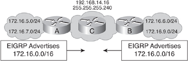
![]() You can resolve this problem by disabling automatic summarization when running RIPv2 or EIGRP. Classless routers use the longest prefix match when selecting a route from the routing table. Therefore, if one of the routers advertises without summarizing, the other routers see subnet routes and the summary route. The other routers can then select the longest prefix match and follow the correct path. For example, in Figure 1-15, if Router A continues to summarize to 172.16.0.0/16 and Router B is configured not to summarize, Router C receives explicit routes for 172.16.6.0/24 and 172.16.9.0/24, along with the summarized route to 172.16.0.0/16. All traffic for Router B subnets is sent to Router B, and all other traffic for the 172.16.0.0 network is sent to Router A.
You can resolve this problem by disabling automatic summarization when running RIPv2 or EIGRP. Classless routers use the longest prefix match when selecting a route from the routing table. Therefore, if one of the routers advertises without summarizing, the other routers see subnet routes and the summary route. The other routers can then select the longest prefix match and follow the correct path. For example, in Figure 1-15, if Router A continues to summarize to 172.16.0.0/16 and Router B is configured not to summarize, Router C receives explicit routes for 172.16.6.0/24 and 172.16.9.0/24, along with the summarized route to 172.16.0.0/16. All traffic for Router B subnets is sent to Router B, and all other traffic for the 172.16.0.0 network is sent to Router A.
![]() Another example is shown in Figure 1-16 and Figure 1-17. In the RIPv2 network illustrated in Figure 1-16, notice what routing information Router C, which is attached to Router B via the 192.168.5.0/24 network, has about network 172.16.0.0. Router B automatically summarizes the 172.16.1.0/24 and 172.16.2.0/24 subnets to 172.16.0.0/16 before sending the route to Router C, because it is sent over an interface in a different network. Instead of using the subnet mask known to Router B (/24), Router C uses this default classful mask for a Class B address (/16) when it stores the 172.16.0.0 information in its routing table.
Another example is shown in Figure 1-16 and Figure 1-17. In the RIPv2 network illustrated in Figure 1-16, notice what routing information Router C, which is attached to Router B via the 192.168.5.0/24 network, has about network 172.16.0.0. Router B automatically summarizes the 172.16.1.0/24 and 172.16.2.0/24 subnets to 172.16.0.0/16 before sending the route to Router C, because it is sent over an interface in a different network. Instead of using the subnet mask known to Router B (/24), Router C uses this default classful mask for a Class B address (/16) when it stores the 172.16.0.0 information in its routing table.


![]() In the OSPF network shown in Figure 1-16, Router B passes the subnet and subnet mask information to Router C, and Router C puts the subnet details in its routing table. Router C does not need to use default classful masks for the received routing information because the subnet mask is included in the routing update, and OSPF does not automatically summarize networks.
In the OSPF network shown in Figure 1-16, Router B passes the subnet and subnet mask information to Router C, and Router C puts the subnet details in its routing table. Router C does not need to use default classful masks for the received routing information because the subnet mask is included in the routing update, and OSPF does not automatically summarize networks.
![]() You can disable automatic summarization for RIPv2 and EIGRP with the no auto-summary router configuration command. When automatic summarization is disabled, RIPv2 and EIGRP forward subnet information, even over interfaces belonging to different major networks. In the RIPv2 network in Figure 1-17, automatic summarization has been disabled. Notice that now the routing table is the same for both the RIPv2 and the OSPF routers.
You can disable automatic summarization for RIPv2 and EIGRP with the no auto-summary router configuration command. When automatic summarization is disabled, RIPv2 and EIGRP forward subnet information, even over interfaces belonging to different major networks. In the RIPv2 network in Figure 1-17, automatic summarization has been disabled. Notice that now the routing table is the same for both the RIPv2 and the OSPF routers.
| Note |
|
RIP
![]() This section describes the two versions of RIP—RIPv1 and RIPv2—and how to configure them. Later chapters in this book detail other routing protocols.
This section describes the two versions of RIP—RIPv1 and RIPv2—and how to configure them. Later chapters in this book detail other routing protocols.
Characteristics of RIPv1
![]() RIPv1 is described in RFC 1058, Routing Information Protocol. Its key characteristics include the following:
RIPv1 is described in RFC 1058, Routing Information Protocol. Its key characteristics include the following:
- Hop count is used as the metric for path selection.
- The maximum allowable hop count is 15.
- Routing updates are broadcast every 30 seconds by default. Because it is a distance vector routing protocol, updates are sent even if no change has occurred.
- RIP can load balance over as many as 16 equal-cost paths (4 paths by default).
- It has no authentication support.
| Note |
|
![]() RIPv1 is a classful distance vector routing protocol that does not send the subnet mask in its updates. Therefore, RIPv1 does not support VLSM or discontiguous subnets. RIPv1 automatically summarizes at the network boundary and cannot be configured not to.
RIPv1 is a classful distance vector routing protocol that does not send the subnet mask in its updates. Therefore, RIPv1 does not support VLSM or discontiguous subnets. RIPv1 automatically summarizes at the network boundary and cannot be configured not to.
Characteristics of RIPv2
![]() RIPv2 is a classless distance vector routing protocol defined in RFC 1721, RIP Version 2 Protocol Analysis; RFC 1722, RIP Version 2 Protocol Applicability Statement; and RFC 2453, RIP Version 2. The most significant addition to RIPv2 is the inclusion of the mask in the RIPv2 routing update packet, allowing RIPv2 to support VLSM and discontiguous subnets. RIPv2 automatically summarizes routes on classful network boundaries. As described earlier, however, you can disable this behavior.
RIPv2 is a classless distance vector routing protocol defined in RFC 1721, RIP Version 2 Protocol Analysis; RFC 1722, RIP Version 2 Protocol Applicability Statement; and RFC 2453, RIP Version 2. The most significant addition to RIPv2 is the inclusion of the mask in the RIPv2 routing update packet, allowing RIPv2 to support VLSM and discontiguous subnets. RIPv2 automatically summarizes routes on classful network boundaries. As described earlier, however, you can disable this behavior.
![]() In addition, RIPv2 uses multicast addressing for more-efficient periodic updating on each interface. RIPv2 uses the 224.0.0.9 multicast address to advertise to other RIPv2 routers. This approach is more efficient than RIPv1’s approach. RIPv1 uses a 255.255.255.255 broadcast address, so all devices, including PCs and servers, must process the update packet. They perform the checksum on the Layer 2 packet and pass it up their IP stack. IP sends the packet to the User Datagram Protocol (UDP) process, and UDP checks to see whether RIP port 520 is available. Most PCs and servers do not have any process running on this port and discard the packet.
In addition, RIPv2 uses multicast addressing for more-efficient periodic updating on each interface. RIPv2 uses the 224.0.0.9 multicast address to advertise to other RIPv2 routers. This approach is more efficient than RIPv1’s approach. RIPv1 uses a 255.255.255.255 broadcast address, so all devices, including PCs and servers, must process the update packet. They perform the checksum on the Layer 2 packet and pass it up their IP stack. IP sends the packet to the User Datagram Protocol (UDP) process, and UDP checks to see whether RIP port 520 is available. Most PCs and servers do not have any process running on this port and discard the packet.
![]() RIP can fit up to 25 networks and subnets in each update, and updates are dispatched every 30 seconds. For example, if the routing table has 1000 subnets, 40 packets are dispatched every 30 seconds (80 packets a minute). With each packet being a broadcast for RIPv1, all devices must look at it; most of the devices discard the packet.
RIP can fit up to 25 networks and subnets in each update, and updates are dispatched every 30 seconds. For example, if the routing table has 1000 subnets, 40 packets are dispatched every 30 seconds (80 packets a minute). With each packet being a broadcast for RIPv1, all devices must look at it; most of the devices discard the packet.
![]() The IP multicast address for RIPv2 has its own multicast MAC address. Devices that can distinguish between a multicast and a broadcast at Layer 2 read the start of the frame and determine whether the destination MAC address is for them. Nonrouting devices can then discard all these packets at the interface level and not use CPU resources or buffer memory for these unwanted packets. Even on devices that cannot distinguish between broadcast and multicast at Layer 2, the worst that will happen is that the RIPv2 updates will be discarded at the IP layer instead of being passed to UDP, because those devices are not using the 224.0.0.9 multicast address.
The IP multicast address for RIPv2 has its own multicast MAC address. Devices that can distinguish between a multicast and a broadcast at Layer 2 read the start of the frame and determine whether the destination MAC address is for them. Nonrouting devices can then discard all these packets at the interface level and not use CPU resources or buffer memory for these unwanted packets. Even on devices that cannot distinguish between broadcast and multicast at Layer 2, the worst that will happen is that the RIPv2 updates will be discarded at the IP layer instead of being passed to UDP, because those devices are not using the 224.0.0.9 multicast address.
![]() RIPv2 also supports security between RIP routers using message-digest or clear-text authentication. (RIPv2 security features are not covered in this book.)
RIPv2 also supports security between RIP routers using message-digest or clear-text authentication. (RIPv2 security features are not covered in this book.)
RIP Configuration Commands
![]() To activate the RIP process (version 1 by default), use the router rip global configuration command.
To activate the RIP process (version 1 by default), use the router rip global configuration command.
![]() By default, the Cisco IOS software processes both RIPv1 and RIPv2 packets. However, it sends only version 1 packets. To configure the software to send and receive packets from only one version, use the version {1 | 2} router configuration command.
By default, the Cisco IOS software processes both RIPv1 and RIPv2 packets. However, it sends only version 1 packets. To configure the software to send and receive packets from only one version, use the version {1 | 2} router configuration command.
![]() To select participating attached networks, use the network network-number router configuration command, specifying the major classful network number. Regardless of the RIP version, at least one network command, using a classful network number, is required under the RIP routing process.
To select participating attached networks, use the network network-number router configuration command, specifying the major classful network number. Regardless of the RIP version, at least one network command, using a classful network number, is required under the RIP routing process.
![]() Although the RIP version command controls RIP’s overall default behavior, you might need to control the version of RIP on a per-interface basis, for example when you are connecting legacy RIP networks to newer networks. To control the version of RIP on each interface, use the ip rip {send | receive} version {1 | 2 | 1 2} interface configuration command.
Although the RIP version command controls RIP’s overall default behavior, you might need to control the version of RIP on a per-interface basis, for example when you are connecting legacy RIP networks to newer networks. To control the version of RIP on each interface, use the ip rip {send | receive} version {1 | 2 | 1 2} interface configuration command.
![]() By default, automatic summarization across network boundaries is activated for all networks in both versions of RIP. Manually summarizing routes in RIPv2 improves scalability and efficiency in large networks because the more-specific routes are not advertised. Only the summary routes are advertised, thus reducing the size of the IP routing table and allowing the router to handle more routes.
By default, automatic summarization across network boundaries is activated for all networks in both versions of RIP. Manually summarizing routes in RIPv2 improves scalability and efficiency in large networks because the more-specific routes are not advertised. Only the summary routes are advertised, thus reducing the size of the IP routing table and allowing the router to handle more routes.
![]() Manual summarization is done at the interface. One limitation of RIPv2 is that routes can be summarized only up to the classful network boundary; RIPv2 does not support classless interdomain routing (CIDR)-type summarization to the left of the classful boundary.
Manual summarization is done at the interface. One limitation of RIPv2 is that routes can be summarized only up to the classful network boundary; RIPv2 does not support classless interdomain routing (CIDR)-type summarization to the left of the classful boundary.
| Note |
![]() To summarize RIP routes on nonclassful boundaries, do the following:
To summarize RIP routes on nonclassful boundaries, do the following:
- Turn off automatic summarization using the no auto-summary router configuration command.
- Use the ip summary-address rip network-number mask interface configuration command to define a network number and mask that meet the particular summarization requirement.
![]() Figure 1-18 illustrates how RIPv1 and RIPv2 may coexist in the same network. Router A is running RIPv2, and Router C is running RIPv1. Router B runs both versions of RIP. Notice that the ip rip send version 1 and ip rip receive version 1 commands are required only on interface Serial 0/0/3 of Router B, because RIPv2 is configured as the primary version for all interfaces. The Serial 0/0/3 interface has to be manually configured to support RIPv1 so that it can connect correctly with Router C.
Figure 1-18 illustrates how RIPv1 and RIPv2 may coexist in the same network. Router A is running RIPv2, and Router C is running RIPv1. Router B runs both versions of RIP. Notice that the ip rip send version 1 and ip rip receive version 1 commands are required only on interface Serial 0/0/3 of Router B, because RIPv2 is configured as the primary version for all interfaces. The Serial 0/0/3 interface has to be manually configured to support RIPv1 so that it can connect correctly with Router C.


![]() An ip summary-address rip command is configured on Router A along with the no auto-summary command. The combination of these two commands allows Router A to send the 172.16.1.0 subnet detail to Router B. Because the interface between Router A and Router B is in a different network (10.0.0.0), the default behavior for Router A is to send only the classful summarization (172.16.0.0) to Router B.
An ip summary-address rip command is configured on Router A along with the no auto-summary command. The combination of these two commands allows Router A to send the 172.16.1.0 subnet detail to Router B. Because the interface between Router A and Router B is in a different network (10.0.0.0), the default behavior for Router A is to send only the classful summarization (172.16.0.0) to Router B.
| Note |
|
![]() Commands used to verify RIP include the show ip route command to examine the IP routing table, and the show ip rip database command to display summary address entries in the RIP routing database entries if relevant child routes are being summarized.
Commands used to verify RIP include the show ip route command to examine the IP routing table, and the show ip rip database command to display summary address entries in the RIP routing database entries if relevant child routes are being summarized.
Populating the Routing Table
![]() This section describes how Cisco routers populate their routing tables. Administrative distance, routing metrics, and floating static routes are discussed. The criteria routers use for inserting routes into the IP routing table are described.
This section describes how Cisco routers populate their routing tables. Administrative distance, routing metrics, and floating static routes are discussed. The criteria routers use for inserting routes into the IP routing table are described.
Administrative Distance
![]() Most routing protocols have metric structures and algorithms that are incompatible with other protocols. It is critical that a network using multiple routing protocols be able to seamlessly exchange route information and be able to select the best path across multiple protocols. Cisco routers use a value called administrative distance to select the best path when they learn of two or more routes to the same destination with the same prefix from different routing protocols.
Most routing protocols have metric structures and algorithms that are incompatible with other protocols. It is critical that a network using multiple routing protocols be able to seamlessly exchange route information and be able to select the best path across multiple protocols. Cisco routers use a value called administrative distance to select the best path when they learn of two or more routes to the same destination with the same prefix from different routing protocols.
![]() Administrative distance rates a routing protocol’s believability or trustworthiness. Cisco has assigned a default administrative distance value to each routing protocol supported on its routers. Each routing protocol is prioritized in the order of most to least believable.
Administrative distance rates a routing protocol’s believability or trustworthiness. Cisco has assigned a default administrative distance value to each routing protocol supported on its routers. Each routing protocol is prioritized in the order of most to least believable.
![]() The administrative distance is a value between 0 and 255. The lower the administrative distance value, the higher the protocol’s believability or trustworthiness. Table 1-6 lists the default administrative distance of the protocols supported by Cisco routers.
The administrative distance is a value between 0 and 255. The lower the administrative distance value, the higher the protocol’s believability or trustworthiness. Table 1-6 lists the default administrative distance of the protocols supported by Cisco routers.
| Note |
|
![]() For example, in Figure 1-19, if Router A receives a route to network 10.0.0.0 from RIP and also receives a route to the same network from OSPF, the router compares RIP’s administrative distance, 120, with OSPF’s administrative distance, 110, and determines that OSPF is more believable. The router therefore adds the OSPF route to network 10.0.0.0 to the routing table.
For example, in Figure 1-19, if Router A receives a route to network 10.0.0.0 from RIP and also receives a route to the same network from OSPF, the router compares RIP’s administrative distance, 120, with OSPF’s administrative distance, 110, and determines that OSPF is more believable. The router therefore adds the OSPF route to network 10.0.0.0 to the routing table.
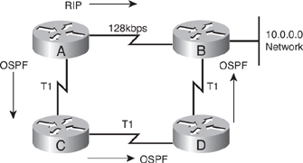
Routing Protocol Metrics
![]() RIPv1 and RIPv2 use only the hop count to determine the best path (the path with the smallest hop count is preferred). Because they do not consider bandwidth, RIPv1 and RIPv2 are not suitable for networks that have significantly different transmission speeds on redundant paths. For networks that use diverse media on redundant paths, routing protocols must account for bandwidth and possibly the delay of the links.
RIPv1 and RIPv2 use only the hop count to determine the best path (the path with the smallest hop count is preferred). Because they do not consider bandwidth, RIPv1 and RIPv2 are not suitable for networks that have significantly different transmission speeds on redundant paths. For networks that use diverse media on redundant paths, routing protocols must account for bandwidth and possibly the delay of the links.
![]() By default EIGRP uses the minimum bandwidth and accumulated delay of the path toward the destination network in its metric calculation. Other parameters (reliability and load) can also be used, but should be configured only if the consequences are fully understood because, if misconfigured, they might affect convergence and cause routing loops. The EIGRP minimum bandwidth is the minimum (slowest) bandwidth along the path. An interface’s bandwidth is either the default value of the interface or as specified by the bandwidth command—this command is usually used on serial interfaces.
By default EIGRP uses the minimum bandwidth and accumulated delay of the path toward the destination network in its metric calculation. Other parameters (reliability and load) can also be used, but should be configured only if the consequences are fully understood because, if misconfigured, they might affect convergence and cause routing loops. The EIGRP minimum bandwidth is the minimum (slowest) bandwidth along the path. An interface’s bandwidth is either the default value of the interface or as specified by the bandwidth command—this command is usually used on serial interfaces.
| Note |
|
![]() In the case of link-state protocols (OSPF and IS-IS), a cumulative cost or metric is used (the lowest cost or metric path is selected). OSPF uses cost for path calculation, usually reflecting the link’s bandwidth (the OSPF RFC does not specify what the cost should be, but on Cisco routers it defaults to being inversely proportional to the link’s bandwidth). As a result, the highest bandwidth (lowest cost) is used to select the best path. The IS-IS interface metric defaults to 10 on Cisco routers; this value can be changed, to reflect different bandwidths, for example.
In the case of link-state protocols (OSPF and IS-IS), a cumulative cost or metric is used (the lowest cost or metric path is selected). OSPF uses cost for path calculation, usually reflecting the link’s bandwidth (the OSPF RFC does not specify what the cost should be, but on Cisco routers it defaults to being inversely proportional to the link’s bandwidth). As a result, the highest bandwidth (lowest cost) is used to select the best path. The IS-IS interface metric defaults to 10 on Cisco routers; this value can be changed, to reflect different bandwidths, for example.
| Note |
|
![]() BGP uses many attributes to select the best path. One of these is the AS-path attribute; the length of this attribute is the number of autonomous systems that must be traversed to reach a destination, and is usually a factor that influences the path selection. Another attribute is the multiexit discriminator (MED). The MED attribute is called the metric in the Cisco IOS. In the output of the show ip bgp command for example, the MED is displayed in the metric column. BGP incorporates additional path attributes that can influence routing decisions; these can be manually configured.
BGP uses many attributes to select the best path. One of these is the AS-path attribute; the length of this attribute is the number of autonomous systems that must be traversed to reach a destination, and is usually a factor that influences the path selection. Another attribute is the multiexit discriminator (MED). The MED attribute is called the metric in the Cisco IOS. In the output of the show ip bgp command for example, the MED is displayed in the metric column. BGP incorporates additional path attributes that can influence routing decisions; these can be manually configured.
Criteria for Inserting Routes into the IP Routing Table
![]() A Cisco router chooses the best route for a specific destination among those presented by routing protocols, manual configuration, and various other means by considering the following four criteria:
A Cisco router chooses the best route for a specific destination among those presented by routing protocols, manual configuration, and various other means by considering the following four criteria:
- Valid next-hop IP address— As each routing process receives updates and other information, the router first verifies that the route has a valid next-hop IP address.
- Metric— If the next hop is valid, the routing protocol chooses the best path to any given destination based on the lowest metric. The routing protocol offers this path to the routing table. For example, if EIGRP learns of a path to 10.1.1.0/24 and decides that this particular path is the best EIGRP path to this destination, the routing protocol offers the learned path to the routing table.
- Administrative distance— The next consideration is administrative distance. If more than one route exists for the same network, and with the same prefix, from different routing sources, the router decides which route to install based on the administrative distance of the route’s source. The route with the lowest administrative distance is installed in the routing table. Routes with higher administrative distances are rejected. For example, if both EIGRP and OSPF offered the 10.1.1.0/24 route, the EIGRP route would be installed in the routing table because EIGRP has a lower administrative distance (by default).
- Prefix— The router looks at the prefix being advertised. Routes to the same network but with different prefixes can coexist in the routing table. For example, suppose the router has three routing processes running on it, and the routing protocols have received and installed the following routes:
- RIPv2: 192.168.32.0/26
- OSPF: 192.168.32.0/24
- EIGRP: 192.168.32.0/19
Because each route has a different prefix length (different subnet mask), the routes are considered different destinations and are all installed in the routing table. As discussed in the “Classless Routing Protocol Concepts” section, earlier in this chapter, if more than one entry in the routing table matches a particular destination, the longest prefix match in the routing table is used. Therefore, in this example, if a packet arrives for the address 192.168.32.5, the router will use the 192.168.32.0/26 subnet, advertised by RIPv2, because it is the longest match for this address. -
Floating Static Routes
![]() Based on the default administrative distances, routers believe static routes over any dynamically learned route. Sometimes, however, this default behavior might not be the desired behavior. For example, when you configure a static route as a backup to a dynamically learned route, you do not want the static route to be used as long as the dynamic route is available. In this case, you can manipulate the optional distance parameter in the ip route command to make the static route appear less desirable than another static or dynamic route.
Based on the default administrative distances, routers believe static routes over any dynamically learned route. Sometimes, however, this default behavior might not be the desired behavior. For example, when you configure a static route as a backup to a dynamically learned route, you do not want the static route to be used as long as the dynamic route is available. In this case, you can manipulate the optional distance parameter in the ip route command to make the static route appear less desirable than another static or dynamic route.
![]() A static route that appears in the routing table only when the primary route goes away is called a floating static route. The administrative distance of the static route is configured to be higher than the administrative distance of the primary route and it “floats” above the primary route, until the primary route is no longer available.
A static route that appears in the routing table only when the primary route goes away is called a floating static route. The administrative distance of the static route is configured to be higher than the administrative distance of the primary route and it “floats” above the primary route, until the primary route is no longer available.
![]() In Figure 1-20, Routers A and B have two connections: a point-to-point serial connection that is the primary link, and a backup connection to be used if the other line goes down. Both routers use EIGRP, but do not use a routing protocol on the backup 172.16.1.0 network link.
In Figure 1-20, Routers A and B have two connections: a point-to-point serial connection that is the primary link, and a backup connection to be used if the other line goes down. Both routers use EIGRP, but do not use a routing protocol on the backup 172.16.1.0 network link.


![]() A static route that points to the backup interface of the other router has been created on each router. Because EIGRP has an administrative distance of 90, the static route has been given an administrative distance of 100. As long as Router A has an EIGRP route to the 10.0.0.0 network, it appears more believable than the static route, and the EIGRP route is used. If the serial link goes down, deleting the EIGRP route, Router A will insert the static route into the routing table. A similar process happens on Router B with its route to the 172.17.0.0 network.
A static route that points to the backup interface of the other router has been created on each router. Because EIGRP has an administrative distance of 90, the static route has been given an administrative distance of 100. As long as Router A has an EIGRP route to the 10.0.0.0 network, it appears more believable than the static route, and the EIGRP route is used. If the serial link goes down, deleting the EIGRP route, Router A will insert the static route into the routing table. A similar process happens on Router B with its route to the 172.17.0.0 network.
IP Routing Protocol Comparisons
![]() This section provides comparative summaries of routing protocols.
This section provides comparative summaries of routing protocols.
![]() IGRP, EIGRP, and OSPF are transport layer protocols, because, like UDP and TCP, they run directly over IP. In contrast, RIP and BGP both reside at the application layer. RIP uses UDP as its transport protocol; its updates are sent unreliably with best-effort delivery. BGP uses TCP as its transport protocol; it takes advantage of TCP’s reliability mechanisms and windowing. Table 1-7 lists the protocol numbers, port numbers, and how reliability is handled for the various routing protocols.
IGRP, EIGRP, and OSPF are transport layer protocols, because, like UDP and TCP, they run directly over IP. In contrast, RIP and BGP both reside at the application layer. RIP uses UDP as its transport protocol; its updates are sent unreliably with best-effort delivery. BGP uses TCP as its transport protocol; it takes advantage of TCP’s reliability mechanisms and windowing. Table 1-7 lists the protocol numbers, port numbers, and how reliability is handled for the various routing protocols.
|
|
|
| |
|---|---|---|---|
|
|
|
|
|
|
|
|
|
|
|
|
|
|
|
|
|
|
|
|
|
|
|
|
|
| Note |
|
![]() Table 1-8 compares some of the characteristics of the different routing protocols.
Table 1-8 compares some of the characteristics of the different routing protocols.
|
|
|
|
|
|
|
|---|---|---|---|---|---|
|
|
|
|
| ||
|
|
|
| |||
|
|
|
| |||
|
|
|
|
| ||
|
|
|
|
|
|
|
|
|
|
|
|
|
|
|
|
|
|
|
|
|
|
|
|
|
|
|
|
|
|
|
|
|
|
|
Routing and Routing Protocols Within the Enterprise Composite Network Model
![]() Routing protocols are an integral part of any network. When designing a network using the architectures and models introduced in this chapter, routing protocol selection and planning are among the design decisions to be made. Although the best practice is to use one IP routing protocol throughout the enterprise if possible, in many cases multiple routing protocols might be required, as illustrated in Figure 1-21. For example, BGP might be used in the Corporate Internet module, whereas static routes are often used for remote-access and VPN users. Therefore, enterprises might have to deal with multiple routing protocols.
Routing protocols are an integral part of any network. When designing a network using the architectures and models introduced in this chapter, routing protocol selection and planning are among the design decisions to be made. Although the best practice is to use one IP routing protocol throughout the enterprise if possible, in many cases multiple routing protocols might be required, as illustrated in Figure 1-21. For example, BGP might be used in the Corporate Internet module, whereas static routes are often used for remote-access and VPN users. Therefore, enterprises might have to deal with multiple routing protocols.


![]() The Enterprise Composite Network Model can assist in determining where each routing protocol is implemented, where the boundaries between protocols are, and how traffic flows between them will be managed.
The Enterprise Composite Network Model can assist in determining where each routing protocol is implemented, where the boundaries between protocols are, and how traffic flows between them will be managed.
![]() Each routing protocol has its own unique characteristics. You can use a table, like Table 1-9, to identify the characteristics of the routing protocols that are being considered for a network, so that they can be compared and a decision on which to use can be made.
Each routing protocol has its own unique characteristics. You can use a table, like Table 1-9, to identify the characteristics of the routing protocols that are being considered for a network, so that they can be compared and a decision on which to use can be made.
|
|
|
|
|
|---|---|---|---|
|
|
|
|
|
|
|
|
|
|
|
|
|
|
|
|
|
|
|
|
|
|
|
|
|
![]() Although static routes may be used (for example, for Internet connectivity) and RIPv2 is a plausible choice for smaller networks, EIGRP and OSPF are the recommended protocols within the Enterprise. BGP is required for inter–autonomous system connectivity on the Internet.
Although static routes may be used (for example, for Internet connectivity) and RIPv2 is a plausible choice for smaller networks, EIGRP and OSPF are the recommended protocols within the Enterprise. BGP is required for inter–autonomous system connectivity on the Internet.
![]() Subsequent chapters in this book cover EIGRP, OSPF, and BGP characteristics, operation, and configuration, and manipulating routing updates and traffic.
Subsequent chapters in this book cover EIGRP, OSPF, and BGP characteristics, operation, and configuration, and manipulating routing updates and traffic.
Summary
![]() In this chapter, you learned about network models, requirements, and implementation plans, and reviewed IP routing principles. The chapter focused on the following topics:
In this chapter, you learned about network models, requirements, and implementation plans, and reviewed IP routing principles. The chapter focused on the following topics:
- Traffic in converged networks, including voice and video, voice applications, mission-critical, transactional, routing protocol, and network management.
- The three phases of the Cisco IIN: integrated transport, integrated services, and integrated applications.
- The three layers of the Cisco SONA architectural framework: networked infrastructure, interactive services, application.
- The components of the Cisco Enterprise Architecture for integration of the entire network: campus, data center, branches, teleworkers, and WAN.
- The traditional hierarchical network model with its three layers: core, distribution, and access.
- The Cisco Enterprise Composite Network Model with its three functional areas and their associated modules:
- Enterprise Campus: Building, Building Distribution, Core, Edge Distribution, Server Farm, Management
- Enterprise Edge: E-commerce, Corporate Internet, VPN and Remote Access, WAN
- Service Provider Edge: ISP, PSTN, Frame Relay/ATM.
-
- The two approaches to implementing changes to a network: using an ad hoc approach or using a structured approach.
- Four models used in IT services lifecycles: Cisco Lifecycle Services (PPDIOO), ITIL, FCAPS, and TMN.
- Creating an implementation plan, as part of the network design phase, including
- Network convergence, when routing tables on all routers in the network are synchronized and contain a route to all destination networks. Convergence time is the time it takes for all routers in a network to agree on the new topology.
- Static routing characteristics and configuration (using the ip route global configuration command).
- Characteristics and configuration (with the router odr global configuration command) of ODR, which uses CDP to carry network information between spoke (stub) routers and the hub router.
- Dynamic routing protocol characteristics, including
- The metric, a value that routing protocols use to measure paths to a destination.
- Configuration, using the router protocol global configuration command.
- Distance vector routing, in which all the routers periodically send their routing tables (or a portion of their tables) to only their neighboring routers.
- Link-state routing, in which each of the routers sends the state of its own interfaces (its links) to all other routers (or to all routers in a part of the network, known as an area) only when there is a change.
- Advanced distance vector routing, in which routers send only changed information when there is a change (similar to link-state protocols) but only to neighboring routers (similar to distance vector protocols).
- Classful routing protocol updates, which do not include the subnet mask. Classful protocols (such as RIPv1) do not support VLSM or discontiguous subnets and must automatically summarize across the network boundary to the classful address.
- Classless routing protocol updates, which do include the subnet mask. Classless protocols (such as RIPv2, EIGRP, and OSPF) do support VLSM and discontiguous subnets, and do not have to summarize automatically across network boundaries.
-
- RIPv1 and RIPv2 characteristics and configuration, including
- The router rip global configuration command to enable RIP
- The version {1 | 2} router configuration command to send and receive packets from only one version
- The network network-number router configuration command to configure RIP to start up the protocol on interfaces in that network, and send advertisements for the networks connected to the specified interfaces.
- The ip rip {send | receive} version {1 | 2 | 1 2} interface configuration command to control the version of RIP on each interface
- The no auto-summary router configuration command to turn off automatic summarization
- The ip summary-address rip network-number mask interface configuration command to define a network number and mask that meet the particular summarization requirement
-
- The process that Cisco routers use to populate their routing tables:
- Valid next-hop IP address— The router first verifies that the route has a valid next-hop IP address.
- Metric— If the next hop is valid, the routing protocol chooses the best path to any given destination based on the lowest metric and offers this path to the routing table.
- Administrative distance— If more than one route exists for the same network, and with the same prefix from different routing sources, the router decides which route to install based on the administrative distance of the route’s source. The administrative distance is a value between 0 and 255. The lower the administrative distance value, the higher the protocol’s believability or trustworthiness. The route with the lowest administrative distance is installed in the routing table. Routes with higher administrative distances are rejected.
- Prefix— The router looks at the prefix being advertised; routes to the same network but with different prefixes can coexist in the routing table.
-
- A comparison of the various IP routing protocols. Multiple protocols may be used within the modules of the Enterprise Composite Network Model. EIGRP and OSPF are the recommended protocols within the Enterprise; BGP is required for inter–autonomous system connectivity on the Internet.
0 comments
Post a Comment