
 Complex Enterprise Network Frameworks, Architectures, and Models
![]() This section introduces converged networks and the variety of traffic within them. To accommodate the requirements of such networks, Cisco has introduced the Intelligent Information Network (IIN) strategy, along with the Service-Oriented Network Architecture (SONA) framework, which guides the evolution of enterprise networks toward an IIN, both of which are described in this section.
This section introduces converged networks and the variety of traffic within them. To accommodate the requirements of such networks, Cisco has introduced the Intelligent Information Network (IIN) strategy, along with the Service-Oriented Network Architecture (SONA) framework, which guides the evolution of enterprise networks toward an IIN, both of which are described in this section.
![]() This section also introduces the components of the Cisco Enterprise Architecture, and describes the traditional hierarchical network model and the Enterprise Composite Network Model.
This section also introduces the components of the Cisco Enterprise Architecture, and describes the traditional hierarchical network model and the Enterprise Composite Network Model.
Traffic Conditions in a Converged Network
![]() A converged network is one in which data, voice, and video traffic coexist on a single network. When voice and video are transported across a network, the voice and video are seen by the network as being just like any other application data.
A converged network is one in which data, voice, and video traffic coexist on a single network. When voice and video are transported across a network, the voice and video are seen by the network as being just like any other application data.
![]() Converged networks contain a variety of different types of traffic, including the following:
Converged networks contain a variety of different types of traffic, including the following:
- Voice and video traffic— Examples include IP telephony, video broadcast, and conferencing.
- Voice applications traffic— Generated by voice-related applications, such as contact centers.
- Mission-critical traffic— Generated by applications critical to an organization (for example, information generated by a stock exchange application at a finance company, patient records at a hospital, and so forth).
- Transactional traffic— Generated by applications such as those for e-commerce.
- Routing protocol traffic— Data from whichever routing protocols are running in the network, such as the Routing Information Protocol (RIP), Open Shortest Path First Protocol (OSPF), Enhanced Interior Gateway Routing Protocol (EIGRP), Intermediate System-to-Intermediate System Protocol (IS-IS), and Border Gateway Protocol (BGP).
- Network management traffic— Including information about the status of the network and its devices.
| Note |
|
![]() The requirements on the network differ significantly depending on the mix of traffic types, especially in terms of security and performance. For example, voice and video performance requirements include constant bandwidth and low delay and jitter (variation in delay), whereas transactional traffic requires high reliability and security with relatively low bandwidth. Voice applications, such as IP telephony, also require high reliability and availability because users expect to hear a “dial tone” sound when they pick up their phone in an IP network, just as they do in a traditional telephone network. Video traffic is frequently carried as IP multicast traffic, requiring multicast features to be enabled on the network. To meet these traffic requirements, converged networks use quality of service (QoS) mechanisms so that, for example, voice and video traffic are given priority over web-based traffic.
The requirements on the network differ significantly depending on the mix of traffic types, especially in terms of security and performance. For example, voice and video performance requirements include constant bandwidth and low delay and jitter (variation in delay), whereas transactional traffic requires high reliability and security with relatively low bandwidth. Voice applications, such as IP telephony, also require high reliability and availability because users expect to hear a “dial tone” sound when they pick up their phone in an IP network, just as they do in a traditional telephone network. Video traffic is frequently carried as IP multicast traffic, requiring multicast features to be enabled on the network. To meet these traffic requirements, converged networks use quality of service (QoS) mechanisms so that, for example, voice and video traffic are given priority over web-based traffic.
![]() Several security strategies, such as device hardening with strict access control and authentication, intrusion protection, intrusion detection, and traffic protection with encryption, can minimize or possibly eliminate network security threats. Security is a key issue in all networks and becomes even more important in wireless networks.
Several security strategies, such as device hardening with strict access control and authentication, intrusion protection, intrusion detection, and traffic protection with encryption, can minimize or possibly eliminate network security threats. Security is a key issue in all networks and becomes even more important in wireless networks.
Cisco IIN and SONA Framework
![]() To accommodate today’s and tomorrow’s network requirements, the Cisco vision of the future includes the IIN, a strategy that addresses how the network is integrated with businesses and business priorities. The Cisco SONA is an architectural framework that illustrates how to build integrated systems and guides the evolution of enterprise networks toward an IIN.
To accommodate today’s and tomorrow’s network requirements, the Cisco vision of the future includes the IIN, a strategy that addresses how the network is integrated with businesses and business priorities. The Cisco SONA is an architectural framework that illustrates how to build integrated systems and guides the evolution of enterprise networks toward an IIN.
Cisco IIN
![]() The IIN encompasses the following features:
The IIN encompasses the following features:
- Integration of networked resources and information assets that have been largely unlinked— The modern converged networks with integrated voice, video, and data require that IT departments (and other departments that were traditionally responsible for other technologies) more closely link the IT infrastructure with the network.
- Intelligence across multiple products and infrastructure layers— The intelligence built in to each component of the network is extended networkwide and applies end to end.
- Active participation of the network in the delivery of services and applications— With added intelligence, the IIN makes it possible for the network to actively manage, monitor, and optimize service and application delivery across the entire IT environment.
![]() The IIN offers much more than basic connectivity, bandwidth for users, and access to applications. It offers an end-to-end functionality and centralized, unified control that promotes true business transparency and agility.
The IIN offers much more than basic connectivity, bandwidth for users, and access to applications. It offers an end-to-end functionality and centralized, unified control that promotes true business transparency and agility.
![]() With the IIN, Cisco is helping organizations to address new IT challenges, such as the deployment of service-oriented architectures, web services, and virtualization (as described in the upcoming “Phase 2” bullet). The IIN technology vision offers an evolutionary approach that consists of three phases in which functionality can be added to the infrastructure as required, as follows:
With the IIN, Cisco is helping organizations to address new IT challenges, such as the deployment of service-oriented architectures, web services, and virtualization (as described in the upcoming “Phase 2” bullet). The IIN technology vision offers an evolutionary approach that consists of three phases in which functionality can be added to the infrastructure as required, as follows:
- Phase 1: Integrated transport— Everything (data, voice, and video) consolidates onto an IP network for secure network convergence. By integrating data, voice, and video transport into a single, standards-based, modular network, organizations can simplify network management and generate enterprisewide efficiencies. Network convergence also lays the foundation for a new class of IP-enabled applications, delivered through Cisco Unified Communications solutions.
Note Cisco Unified Communications is the name, launched in March 2006, for the entire range of what were previously known as Cisco IP Communications products. These include all call control, conferencing, voice-mail and messaging, customer contact, IP phone, video telephony, videoconferencing, rich media clients, and voice application products. - Phase 2: Integrated services— When the network infrastructure is converged, IT resources can be pooled and shared, or virtualized, to flexibly address the changing needs of the organization. Integrated services help to unify common elements, such as storage and data center server capacity. By extending this virtualization concept to encompass server, storage, and network elements, an organization can transparently use all of its resources more efficiently. Business continuity is also enhanced because in the event of a local systems failure, shared resources across the IIN can provide needed services.
- Phase 3: Integrated applications— This phase focuses on making the network application-aware so that it can optimize application performance and more efficiently deliver networked applications to users. With Application-Oriented Networking (AON) technology, Cisco has entered this third IIN phase. In addition to capabilities such as content caching, load balancing, and application-level security, the Cisco AON makes it possible for the network to simplify the application infrastructure by integrating intelligent application message handling, optimization, and security into the existing network.
Cisco SONA Framework
![]() The Cisco SONA architectural framework guides the evolution of enterprise networks toward an IIN. Using the SONA framework, enterprises can improve flexibility and increase efficiency by optimizing applications, business processes, and resources to enable IT to have a greater impact on business.
The Cisco SONA architectural framework guides the evolution of enterprise networks toward an IIN. Using the SONA framework, enterprises can improve flexibility and increase efficiency by optimizing applications, business processes, and resources to enable IT to have a greater impact on business.
![]() The SONA framework uses the extensive product-line services, proven architectures, and experience of Cisco and its partners to help enterprises achieve their business goals.
The SONA framework uses the extensive product-line services, proven architectures, and experience of Cisco and its partners to help enterprises achieve their business goals.
![]() The SONA framework, shown in Figure 1-1, shows how integrated systems can allow a dynamic, flexible architecture and provide for operational efficiency through standardization and virtualization. In this framework, the network is the common element that connects and enables all components of the IT infrastructure.
The SONA framework, shown in Figure 1-1, shows how integrated systems can allow a dynamic, flexible architecture and provide for operational efficiency through standardization and virtualization. In this framework, the network is the common element that connects and enables all components of the IT infrastructure.


![]() The SONA framework outlines the following three layers:
The SONA framework outlines the following three layers:
- Networked infrastructure layer— Interconnects all the IT resources across a converged network foundation. The IT resources include servers, storage, and clients. The networked infrastructure layer represents how these resources exist in different places in the network, including the campus, branch, data center, wide-area network (WAN), metropolitan-area network (MAN), and with the teleworker. The objective of this layer is to provide connectivity, anywhere and anytime.
- Interactive services layer— Enables efficient allocation of resources to applications and business processes delivered through the networked infrastructure. This layer includes these services:
- Application layer— Includes business applications and collaboration applications. The objective of this layer is to meet business requirements and achieve efficiencies by leveraging the interactive services layer.
| Note |
|
![]() For example, within an organization with some remote offices, segmentation can be done to the three basic layers of SONA:
For example, within an organization with some remote offices, segmentation can be done to the three basic layers of SONA:
- The networked infrastructure layer represents the physical infrastructure (that is, the combination of network, servers, clients, and storage hardware that is deployed throughout an enterprise network).
- The interactive services layer represents the network-based functionality by making resources available to applications and business processes. Application delivery, real-time communication, management, mobility, security, transport, and virtualization are included in the interactive services layer.
- The application layer represents the enterprise software that addresses the needs of organizational processes and data flow, often in a distributed manner.
Cisco Network Models
![]() This section describes Cisco network models, starting with the Cisco Enterprise Architecture, followed by the hierarchical network model, and concluding with the Enterprise Composite Network Model.
This section describes Cisco network models, starting with the Cisco Enterprise Architecture, followed by the hierarchical network model, and concluding with the Enterprise Composite Network Model.
Cisco Enterprise Architecture
![]() Cisco provides an enterprisewide systems architecture that helps companies to protect, optimize, and grow the infrastructure that supports their business processes. As illustrated in Figure 1-2, the architecture provides for integration of the entire network—campus, data center, branches, teleworkers, and WAN—offering staff secure access to the tools, processes, and services they require.
Cisco provides an enterprisewide systems architecture that helps companies to protect, optimize, and grow the infrastructure that supports their business processes. As illustrated in Figure 1-2, the architecture provides for integration of the entire network—campus, data center, branches, teleworkers, and WAN—offering staff secure access to the tools, processes, and services they require.


![]() The Cisco Enterprise Campus Architecture combines a core infrastructure of intelligent switching and routing with tightly integrated productivity-enhancing technologies, including IP communications, mobility, and advanced security. The architecture provides the enterprise with high availability through a resilient multilayer design, redundant hardware and software features, and automatic procedures for reconfiguring network paths when failures occur. IP multicast capabilities provide optimized bandwidth consumption, and QoS features ensure that real-time traffic (such as voice, video, or critical data) is not dropped or delayed. Integrated security protects against and mitigates the impact of worms, viruses, and other attacks on the network, including at the switch port level. For example, the Cisco enterprisewide architecture extends support for security standards, such as the Institute for Electrical and Electronic Engineers (IEEE) 802.1x port-based network access control standard and the Extensible Authentication Protocol (EAP). It also provides the flexibility to add IP security (IPsec) and Multiprotocol Label Switching virtual private networks (MPLS VPNs), identity and access management, and virtual local-area networks (VLANs) to compartmentalize access. These features help improve performance and security while decreasing costs.
The Cisco Enterprise Campus Architecture combines a core infrastructure of intelligent switching and routing with tightly integrated productivity-enhancing technologies, including IP communications, mobility, and advanced security. The architecture provides the enterprise with high availability through a resilient multilayer design, redundant hardware and software features, and automatic procedures for reconfiguring network paths when failures occur. IP multicast capabilities provide optimized bandwidth consumption, and QoS features ensure that real-time traffic (such as voice, video, or critical data) is not dropped or delayed. Integrated security protects against and mitigates the impact of worms, viruses, and other attacks on the network, including at the switch port level. For example, the Cisco enterprisewide architecture extends support for security standards, such as the Institute for Electrical and Electronic Engineers (IEEE) 802.1x port-based network access control standard and the Extensible Authentication Protocol (EAP). It also provides the flexibility to add IP security (IPsec) and Multiprotocol Label Switching virtual private networks (MPLS VPNs), identity and access management, and virtual local-area networks (VLANs) to compartmentalize access. These features help improve performance and security while decreasing costs.
![]() The Cisco Enterprise Data Center Architecture is a cohesive, adaptive network architecture that supports requirements for consolidation, business continuance, and security while enabling emerging service-oriented architectures, virtualization, and on-demand computing. Staff, suppliers, or customers can be provided with secure access to applications and resources, simplifying and streamlining management and significantly reducing overhead. Redundant data centers provide backup using synchronous and asynchronous data and application replication. The network and devices offer server and application load balancing to maximize performance. This architecture allows the enterprise to scale without major changes to the infrastructure.
The Cisco Enterprise Data Center Architecture is a cohesive, adaptive network architecture that supports requirements for consolidation, business continuance, and security while enabling emerging service-oriented architectures, virtualization, and on-demand computing. Staff, suppliers, or customers can be provided with secure access to applications and resources, simplifying and streamlining management and significantly reducing overhead. Redundant data centers provide backup using synchronous and asynchronous data and application replication. The network and devices offer server and application load balancing to maximize performance. This architecture allows the enterprise to scale without major changes to the infrastructure.
![]() The Cisco Enterprise Branch Architecture allows enterprises to extend head-office applications and services (such as security, IP communications, and advanced application performance) to thousands of remote locations and users or to a small group of branches. Cisco integrates security, switching, network analysis, caching, and converged voice and video services into a series of integrated services routers (ISRs) in the branch so that the enterprises can deploy new services without buying new routers. This architecture provides secure access to voice, mission-critical data, and video applications—anywhere, anytime. Advanced routing, VPNs, redundant WAN links, application content caching, and local IP telephony call processing features are available with high levels of resilience for all the branch offices. An optimized network uses the WAN and LAN to reduce traffic and save bandwidth and operational expenses. The enterprise can easily support branch offices with the ability to centrally configure, monitor, and manage devices located at remote sites, including tools, such as AutoQoS, which configures devices to handle congestion and bandwidth issues before they affect network performance.
The Cisco Enterprise Branch Architecture allows enterprises to extend head-office applications and services (such as security, IP communications, and advanced application performance) to thousands of remote locations and users or to a small group of branches. Cisco integrates security, switching, network analysis, caching, and converged voice and video services into a series of integrated services routers (ISRs) in the branch so that the enterprises can deploy new services without buying new routers. This architecture provides secure access to voice, mission-critical data, and video applications—anywhere, anytime. Advanced routing, VPNs, redundant WAN links, application content caching, and local IP telephony call processing features are available with high levels of resilience for all the branch offices. An optimized network uses the WAN and LAN to reduce traffic and save bandwidth and operational expenses. The enterprise can easily support branch offices with the ability to centrally configure, monitor, and manage devices located at remote sites, including tools, such as AutoQoS, which configures devices to handle congestion and bandwidth issues before they affect network performance.
![]() The Cisco Enterprise Teleworker Architecture allows enterprises to securely deliver voice and data services to remote small or home offices over a standard broadband access service, providing a business-resiliency solution for the enterprise and a flexible work environment for employees. Centralized management minimizes the IT support costs. Integrated security and identity-based networking services enable the enterprise to extend campus security policies to the teleworker. Staff can securely log in to the network over an always-on VPN and gain access to authorized applications and services from a single cost-effective platform. Productivity can further be enhanced by adding an IP phone, thereby providing cost-effective access to a centralized IP communications system with voice and unified messaging services.
The Cisco Enterprise Teleworker Architecture allows enterprises to securely deliver voice and data services to remote small or home offices over a standard broadband access service, providing a business-resiliency solution for the enterprise and a flexible work environment for employees. Centralized management minimizes the IT support costs. Integrated security and identity-based networking services enable the enterprise to extend campus security policies to the teleworker. Staff can securely log in to the network over an always-on VPN and gain access to authorized applications and services from a single cost-effective platform. Productivity can further be enhanced by adding an IP phone, thereby providing cost-effective access to a centralized IP communications system with voice and unified messaging services.
![]() The Cisco Enterprise WAN Architecture offers the convergence of voice, video, and data services over a single Cisco Unified Communications network, which enables the enterprise to cost-effectively span large geographic areas. QoS, granular service levels, and comprehensive encryption options help ensure the secure delivery of high-quality corporate voice, video, and data resources to all corporate sites, enabling staff to work productively and efficiently wherever they are located. Security is provided with multiservice VPNs (using IPsec and MPLS) over Layer 2 or Layer 3 WANs, hub-and-spoke, or full-mesh topologies.
The Cisco Enterprise WAN Architecture offers the convergence of voice, video, and data services over a single Cisco Unified Communications network, which enables the enterprise to cost-effectively span large geographic areas. QoS, granular service levels, and comprehensive encryption options help ensure the secure delivery of high-quality corporate voice, video, and data resources to all corporate sites, enabling staff to work productively and efficiently wherever they are located. Security is provided with multiservice VPNs (using IPsec and MPLS) over Layer 2 or Layer 3 WANs, hub-and-spoke, or full-mesh topologies.
Cisco Hierarchical Network Model
![]() Traditionally, the three-layer hierarchical model, illustrated in Figure 1-3, has been used in network design, providing a modular framework that allows design flexibility and facilitates implementation and troubleshooting. The hierarchical model divides networks or modular blocks within a network into the access, distribution, and core layers. The features of the hierarchical layers are as follows:
Traditionally, the three-layer hierarchical model, illustrated in Figure 1-3, has been used in network design, providing a modular framework that allows design flexibility and facilitates implementation and troubleshooting. The hierarchical model divides networks or modular blocks within a network into the access, distribution, and core layers. The features of the hierarchical layers are as follows:


- Access layer— This layer is used to grant users access to network devices. In a network campus, the access layer generally incorporates switched LAN devices with ports that provide connectivity to workstations and servers. In the WAN environment, the access layer at remote sites or at teleworkers’ homes provides access to the corporate network across various WAN technologies.
- Distribution layer— This layer aggregates the wiring closet connections and uses switches to segment workgroups and isolate network problems in a campus environment. Similarly, the distribution layer aggregates WAN connections at the edge of the campus and provides policy-based connectivity (in other words, it implements the organization’s policies).
- Core layer (also referred to as the backbone)— The core layer is a high-speed backbone and is designed to switch packets as fast as possible. Because the core is critical for connectivity, it must provide a high level of availability and adapt to changes quickly.
![]() The hierarchical model can be applied to networks that include any type of connectivity, such as LANs, WANs, wireless LANs (WLANs), MANs, and VPNs.
The hierarchical model can be applied to networks that include any type of connectivity, such as LANs, WANs, wireless LANs (WLANs), MANs, and VPNs.
![]() For example, Figure 1-4 demonstrates the model applied to the enterprise campus, and Figure 1-5 demonstrates the model applied to a WAN environment.
For example, Figure 1-4 demonstrates the model applied to the enterprise campus, and Figure 1-5 demonstrates the model applied to a WAN environment.


![]() The hierarchical model is useful for smaller networks, but does not scale well to today’s larger, more complex networks. The Enterprise Composite Network Model, introduced in the following section, provides additional modularity and functionality.
The hierarchical model is useful for smaller networks, but does not scale well to today’s larger, more complex networks. The Enterprise Composite Network Model, introduced in the following section, provides additional modularity and functionality.
Cisco Enterprise Composite Network Model
![]() Cisco has developed a set of best practices for security, comprising a blueprint for network designers and administrators for the proper deployment of security solutions to support network applications and the existing network infrastructure. This blueprint is called “SAFE.” SAFE includes the Enterprise Composite Network Model, which network professionals can use to describe and analyze any modern enterprise network. This model supports larger networks than those designed with only the hierarchical model and clarifies the functional boundaries within the network.
Cisco has developed a set of best practices for security, comprising a blueprint for network designers and administrators for the proper deployment of security solutions to support network applications and the existing network infrastructure. This blueprint is called “SAFE.” SAFE includes the Enterprise Composite Network Model, which network professionals can use to describe and analyze any modern enterprise network. This model supports larger networks than those designed with only the hierarchical model and clarifies the functional boundaries within the network.
| Note |
|
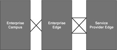
![]() The Enterprise Composite Network Model first divides the network into three functional areas, as illustrated in Figure 1-6 and described as follows:
The Enterprise Composite Network Model first divides the network into three functional areas, as illustrated in Figure 1-6 and described as follows:
- Enterprise Campus— This functional area contains the modules required to build a hierarchical, highly robust campus network. Access, distribution, and core principles are applied to these modules appropriately.
- Enterprise Edge— This functional area aggregates connectivity from the various elements at the edge of the enterprise network, including to remote locations, the Internet, and remote users.
- Service Provider Edge— This area is not implemented by the organization; instead, it is included to represent connectivity to service providers such as Internet service providers (ISPs), WAN providers, and the public switched telephone network (PSTN).
![]() As illustrated in Figure 1-7, each of these functional areas contains various network modules. These modules can in turn include hierarchical core, distribution, and access layer functionality.
As illustrated in Figure 1-7, each of these functional areas contains various network modules. These modules can in turn include hierarchical core, distribution, and access layer functionality.


![]() The Enterprise Campus functional area comprises the following modules:
The Enterprise Campus functional area comprises the following modules:
- Building— Contains access switches and end-user devices (including PCs and IP phones).
- Building Distribution— Includes distribution multilayer switches to provide access between workgroups and to the Core.
- Core— Also called the backbone, provides a high-speed connection between buildings themselves, and between buildings and the Server Farm and Edge Distribution modules.
- Edge Distribution— The interface between the Enterprise Campus and the Enterprise Edge functional areas. This module concentrates connectivity to and from all branches and teleworkers accessing the campus via a WAN or the Internet.
- Server Farm— Represents the campus’s data center.
- Management— Represents the network management functionality, including monitoring, logging, security, and other management features within an enterprise.
![]() Figure 1-8 illustrates how the Building, Building Distribution, and Core modules map directly onto the hierarchical model’s access, distribution, and core layers. The figure also shows how multiple buildings can be represented by multiple sets of a Building and a Building Distribution module, with each connected to the Core.
Figure 1-8 illustrates how the Building, Building Distribution, and Core modules map directly onto the hierarchical model’s access, distribution, and core layers. The figure also shows how multiple buildings can be represented by multiple sets of a Building and a Building Distribution module, with each connected to the Core.


![]() The Enterprise Edge functional area is the interface between the Enterprise Campus functional area (through the Edge Distribution module) and the Service Provider Edge functional area. It is composed of the following four modules:
The Enterprise Edge functional area is the interface between the Enterprise Campus functional area (through the Edge Distribution module) and the Service Provider Edge functional area. It is composed of the following four modules:
- E-commerce— Includes the servers, network devices, and so forth necessary for an organization to provide e-commerce functionality, such as online ordering
- Corporate Internet— Provides Internet access for the organization, and passes VPN traffic from external users to the VPN and Remote Access module
- VPN and Remote Access— Terminates VPN traffic and dial-in connections from external users
- WAN— Provides connectivity from remote sites using various WAN technologies
![]() The three modules within the Service Provider Edge functional area are as follows:
The three modules within the Service Provider Edge functional area are as follows:
- ISP— Represents Internet connections (in Figure 1-7, two instances of this module are shown, representing a dual-homed connection to two ISPs)
- PSTN— Represents all nonpermanent connections, including via analog phone, cellular phone, and Integrated Services Digital Network (ISDN)
- Frame Relay/Asynchronous Transfer Mode (ATM)— Represents all permanent connections to remote locations, including via Frame Relay, ATM, leased lines, cable, digital subscriber line (DSL), MPLS, and wireless bridging
| Note |
|
Creating, Documenting, and Executing an Implementation Plan
![]() An effective, documented, implementation plan is a result of good processes and procedures during network design, deployment, and performance testing. This section describes approaches to creating an implementation plan and its associated documentation.
An effective, documented, implementation plan is a result of good processes and procedures during network design, deployment, and performance testing. This section describes approaches to creating an implementation plan and its associated documentation.
Approaches to Creating an Implementation Plan
![]() There are two approaches to implementing changes to a network: using an ad hoc approach or using a structured approach.
There are two approaches to implementing changes to a network: using an ad hoc approach or using a structured approach.
![]() In an ad hoc approach, the network engineer identifies the need for a change, such as a routing protocol implementation, and implements the solution without planning any of the tasks. The many tasks such as connectivity, addressing, routing, and security are implemented and configured as required. New equipment may be added, and new offices may be deployed. With such an approach, it is more likely that scalability issues, suboptimal routing, and security issues can occur. A good implementation plan is required to avoid such difficulties.
In an ad hoc approach, the network engineer identifies the need for a change, such as a routing protocol implementation, and implements the solution without planning any of the tasks. The many tasks such as connectivity, addressing, routing, and security are implemented and configured as required. New equipment may be added, and new offices may be deployed. With such an approach, it is more likely that scalability issues, suboptimal routing, and security issues can occur. A good implementation plan is required to avoid such difficulties.
![]() In a structured approach, the network engineer identifies the need for a network upgrade (for example, a new routing protocol implementation) and starts with planning as the first step. Based on the existing topology, all potential changes are reviewed, and many considerations are taken into account. The design and implementation plan are completed, and may include a new topology, an IP addressing plan, a solution to scalability issues, a link utilization upgrade, remote network connectivity, and changes to other network parameters. The design and implementation plan must meet both technical and business requirements. All details are documented in the implementation plan before the implementation. After the successful implementation, the documentation is updated to include the tools and resources used, and the implementation results.
In a structured approach, the network engineer identifies the need for a network upgrade (for example, a new routing protocol implementation) and starts with planning as the first step. Based on the existing topology, all potential changes are reviewed, and many considerations are taken into account. The design and implementation plan are completed, and may include a new topology, an IP addressing plan, a solution to scalability issues, a link utilization upgrade, remote network connectivity, and changes to other network parameters. The design and implementation plan must meet both technical and business requirements. All details are documented in the implementation plan before the implementation. After the successful implementation, the documentation is updated to include the tools and resources used, and the implementation results.
![]() Many models and methodologies used in IT define a lifecycle approach using various processes to help provide high-quality IT services. Network implementation, including an implementation plan, is just one part of these models. The following are some examples of these models:
Many models and methodologies used in IT define a lifecycle approach using various processes to help provide high-quality IT services. Network implementation, including an implementation plan, is just one part of these models. The following are some examples of these models:
- The Cisco Lifecycle Services approach defines the minimum set of activities needed to help customers successfully deploy and operate Cisco technologies and optimize their performance throughout the lifecycle of the network. The Cisco Lifecycle Services approach defines six phases in the network lifecycle and is referred to as the Prepare, Plan, Design, Implement, Operate, and Optimize (PPDIOO) model. The implementation plan is part of the Design phase; implementation is of course part of the Implement phase.
- IT Infrastructure Library (ITIL) is a framework of best practices for IT service management, providing high-quality IT services that are aligned with business requirements and processes. The implementation plan and implementation are part of ITIL best practices.
- The Fault, Configuration, Accounting, Performance, and Security (FCAPS) model is defined by the International Organization for Standardization (ISO) and defines the minimum set of categories needed for successful network management. Five different categories are defined: Fault Management, Configuration Management, Accounting Management, Performance Management, and Security Management. The implementation plan and implementation are part of the Configuration Management category.
- The Telecommunications Management Network (TMN) model is similar to the FCAPS model and defines a framework for the management of telecommunication networks. The Telecommunications Standardization Sector (ITU-T) took the main aspects of the FCAPS Model and refined it to create the TMN framework. The implementation plan and implementation are one of the building blocks within the framework.
![]() Each organization has unique requirements. The model and its elements chosen should fit the organization, and its business and technical requirements. Different models may be combined and adapted for an optimal fit. For example, the service components, processes, and procedures needed to create an implementation plan successfully can be chosen to help ensure a successful implementation.
Each organization has unique requirements. The model and its elements chosen should fit the organization, and its business and technical requirements. Different models may be combined and adapted for an optimal fit. For example, the service components, processes, and procedures needed to create an implementation plan successfully can be chosen to help ensure a successful implementation.
![]() After the model has been selected, the cost-effective tools that support the model are chosen to allow a successful deployment of Cisco technologies with optimized performance.
After the model has been selected, the cost-effective tools that support the model are chosen to allow a successful deployment of Cisco technologies with optimized performance.
![]() After the requirements, models, and tools have been defined and collected, the implementation plan can be created.
After the requirements, models, and tools have been defined and collected, the implementation plan can be created.
| Note |
|
Creating an Implementation Plan
![]() As detailed in the Cisco Press book Authorized Self-Study Guide: Designing for Cisco Internetwork Solutions (DESGN), Second Edition, the design methodology recommended for use with the PPDIOO model includes three basic steps:
As detailed in the Cisco Press book Authorized Self-Study Guide: Designing for Cisco Internetwork Solutions (DESGN), Second Edition, the design methodology recommended for use with the PPDIOO model includes three basic steps:
![]() When the design is complete, the design implementation process is executed; this process includes the following steps:
When the design is complete, the design implementation process is executed; this process includes the following steps:
|
|
|
|
|
|
|
|
|
![]() Thus, the process of creating the implementation plan is part of the Design phase. Before developing the implementation plan, you must identify all the following information:
Thus, the process of creating the implementation plan is part of the Design phase. Before developing the implementation plan, you must identify all the following information:
- Network specific information, and the activities and tasks associated with developing the implementation plan— The network information includes the existing topology, equipment, and software versions; the IP addressing plan; scalability requirements (summarization, stub areas, and so on); the list of advertised networks; the link utilization; and the metric requirements for primary and backup links. Other requirements to consider include site-specific implementation requirements, the tools required, and specific commands (for configuration and verification) that should be used.
- The dependencies that your implementation plan development has on other service components and the existing network— Implementation risks should be identified and a plan to manage them established.
- The recommended resources to accomplish the activities and tasks associated with the implementation plan development— The implementation schedule and the roles and responsibilities of the resources should also be established.
![]() Based on the information gathered, the network engineer determines the implementation tasks required. For example, topology design, IP addressing, or any other changes might be required to the existing network. After the implementation plan is developed, the solution is implemented and verified, and the documentation is updated.
Based on the information gathered, the network engineer determines the implementation tasks required. For example, topology design, IP addressing, or any other changes might be required to the existing network. After the implementation plan is developed, the solution is implemented and verified, and the documentation is updated.
![]() The following steps are completed during creation and execution of an implementation plan:
The following steps are completed during creation and execution of an implementation plan:
- Selecting the tools and resources required
- Coordinating work with specialists
- Verifying the implementation
- Interpreting performance results
- Documenting the baseline, performance, and recommendations
![]() The tasks in a site-specific implementation plan may include the following:
The tasks in a site-specific implementation plan may include the following:
- Identifying applications and devices to be implemented
- Creating installation tasks and checklists
- Defining device configuration and software requirements
- Creating site-specific device configurations, installation tasks, and checklists
- Creating installation verification tests
Implementation Plan Documentation
![]() The implementation plan documentation must be correct and up-to-date, because it is needed during both implementation and verification. After implementation, all verification steps and results should be added to the documentation so that it will be useful for troubleshooting, and for planning future upgrades and changes to the network.
The implementation plan documentation must be correct and up-to-date, because it is needed during both implementation and verification. After implementation, all verification steps and results should be added to the documentation so that it will be useful for troubleshooting, and for planning future upgrades and changes to the network.
![]() The documentation must also be accessible (for example, to troubleshooting engineers). The documentation should contain all the current information about the equipment and configuration, and should include known issues, the baseline status, and the details and results of the verification tasks.
The documentation must also be accessible (for example, to troubleshooting engineers). The documentation should contain all the current information about the equipment and configuration, and should include known issues, the baseline status, and the details and results of the verification tasks.
![]() The documentation can also be used to create reports about the implementation, including the tasks performed, the schedule, the resources involved, and so forth.
The documentation can also be used to create reports about the implementation, including the tasks performed, the schedule, the resources involved, and so forth.
![]() The implementation plan documentation should include the following:
The implementation plan documentation should include the following:
- Network information
- Tools required
- Resources required
- Implementation plan tasks
- Verification tasks
- Performance measurement and results
![]() The documentation creation process is not finished until the end of the project, when the verification information is added to it.
The documentation creation process is not finished until the end of the project, when the verification information is added to it.
![]() Use a template for an implementation plan and add information to it during every step of the process. If a standard template does not exist within the organization, create one. At the end of the project, archive the documentation so that it can be used to review, troubleshoot, and update the network in the future.
Use a template for an implementation plan and add information to it during every step of the process. If a standard template does not exist within the organization, create one. At the end of the project, archive the documentation so that it can be used to review, troubleshoot, and update the network in the future.
Implementation Plan Example
![]() This section provides an example of the process of creating an implementation plan.
This section provides an example of the process of creating an implementation plan.
Example Network Scenario
![]() In this example, an organization has an existing network that it wants to upgrade. The company wants to implement a scalable solution with a routing protocol that provides fast convergence. For more optimal routing and packet forwarding, hierarchical addressing with the summarization is required. Users require high-speed access to the server farm with redundant connectivity. The company has many remote offices, and a redundant connection to the Internet is required to provide the remote offices with nonstop access to its server farm. For remote offices, a secure connection is implemented to prevent unauthorized persons from accessing their data.
In this example, an organization has an existing network that it wants to upgrade. The company wants to implement a scalable solution with a routing protocol that provides fast convergence. For more optimal routing and packet forwarding, hierarchical addressing with the summarization is required. Users require high-speed access to the server farm with redundant connectivity. The company has many remote offices, and a redundant connection to the Internet is required to provide the remote offices with nonstop access to its server farm. For remote offices, a secure connection is implemented to prevent unauthorized persons from accessing their data.
![]() Network engineers should review the existing topology and other network information needed to implement the new solution. All requirements must be taken into account, and a complete implementation plan must be created and documented; the results of the verification tests must be added to the documentation when they are complete.
Network engineers should review the existing topology and other network information needed to implement the new solution. All requirements must be taken into account, and a complete implementation plan must be created and documented; the results of the verification tests must be added to the documentation when they are complete.
Example Network Requirements
![]() Before the implementation plan can be created, the requirements must be defined, and the existing network characterized.
Before the implementation plan can be created, the requirements must be defined, and the existing network characterized.
![]() The existing topology in this example provides redundant connectivity among all the network devices. Internet connectivity is dual-homed, providing redundant access to the remote sites and World Wide Web resources. The equipment used is able to provide all the functionalities required, but the software version of the operation system must be upgraded.
The existing topology in this example provides redundant connectivity among all the network devices. Internet connectivity is dual-homed, providing redundant access to the remote sites and World Wide Web resources. The equipment used is able to provide all the functionalities required, but the software version of the operation system must be upgraded.
![]() The networking equipment has existing IP addressing that needs to be changed to ensure more optimal routing and forwarding of packets, and to allow summarization. The existing QoS configuration is not affected by the new requirements. The server farm hosts the company’s critical applications, which along with Voice over IP (VoIP), require high priority. OSPF is currently configured in the network; the configuration must be changed to EIGRP because faster convergence time is required.
The networking equipment has existing IP addressing that needs to be changed to ensure more optimal routing and forwarding of packets, and to allow summarization. The existing QoS configuration is not affected by the new requirements. The server farm hosts the company’s critical applications, which along with Voice over IP (VoIP), require high priority. OSPF is currently configured in the network; the configuration must be changed to EIGRP because faster convergence time is required.
![]() The existing configuration is sufficient to provide secure access to internal resources and remote office connectivity.
The existing configuration is sufficient to provide secure access to internal resources and remote office connectivity.
![]() After gathering this information, all details and requirements are documented, including the following:
After gathering this information, all details and requirements are documented, including the following:
- A list of existing and required equipment
- The current and required software versions on the equipment
- The network topology (physical and logical)
- The design documentation
- The current configurations, including IP addressing, summarization, routing, QoS, security, and so forth
- Current link utilization and metrics
- Site-specific requirements, including IP addressing, software required, topology changes, routing protocol requirements, QoS, security, and so forth
Example Network Implementation Plan
![]() The implementation plan can then be created, and includes the following:
The implementation plan can then be created, and includes the following:
- A project contact list and statements of work, to define all the people involved and their commitments to the project
- Site and equipment location information and details of how access to the premises is obtained
- Tools and resources required
- Assumptions made
- Tasks to be performed, including detailed descriptions
- Network staging plan
![]() Table 1-1 is an example template for a project contact list; in this example the project involves Cisco personnel and customer representatives.
Table 1-1 is an example template for a project contact list; in this example the project involves Cisco personnel and customer representatives.
|
| |
|---|---|
|
|
|
|
|
|
|
|
|
|
|
|
|
|
|
![]() Table 1-2 is an example template for an equipment floor plan, to provide equipment location information and access details for the premises.
Table 1-2 is an example template for an equipment floor plan, to provide equipment location information and access details for the premises.
|
|
|
|---|---|
|
| |
|
| |
|
| |
|
| |
|
|
![]() Table 1-3 is an example of a list of tools required by the implementation engineer to do the work detailed in the implementation plan.
Table 1-3 is an example of a list of tools required by the implementation engineer to do the work detailed in the implementation plan.
|
|
|
|---|---|
|
|
|
|
|
|
|
|
|
![]() Table 1-4 is an example implementation task list, providing a breakdown of the steps and a detailed description of each. The output of each activity should be indicated on the implementation record.
Table 1-4 is an example implementation task list, providing a breakdown of the steps and a detailed description of each. The output of each activity should be indicated on the implementation record.
|
| |
|---|---|
|
|
|
|
|
|
|
|
|
|
|
|
|
|
|
|
|
|
![]() After successful implementation, the documentation must be updated to include all the details, verification steps, and results.
After successful implementation, the documentation must be updated to include all the details, verification steps, and results.
0 comments
Post a Comment