![]() Nevertheless, designing an enterprise campus network is no different than designing any large, complex system—such as a piece of software or even something as sophisticated as the international space station. The use of a guiding set of fundamental engineering principles serves to ensure that the campus design provides for the balance of availability, security, flexibility, and manageability required to meet current and future business and technological needs. This chapter introduces you to the concepts of enterprise campus designs, along with an implementation process that can ensure a successful campus network deployment.
Nevertheless, designing an enterprise campus network is no different than designing any large, complex system—such as a piece of software or even something as sophisticated as the international space station. The use of a guiding set of fundamental engineering principles serves to ensure that the campus design provides for the balance of availability, security, flexibility, and manageability required to meet current and future business and technological needs. This chapter introduces you to the concepts of enterprise campus designs, along with an implementation process that can ensure a successful campus network deployment.
 Introduction to Enterprise Campus Network Design
![]() Cisco has several different design models to abstract and modularize the enterprise network. However, for the content in this book the enterprise network is broken down into the following sections:
Cisco has several different design models to abstract and modularize the enterprise network. However, for the content in this book the enterprise network is broken down into the following sections:
-
 Core Backbone
 -
 Campus
 -
 Data Center
 -
 Branch/WAN
 -
 Internet Edge
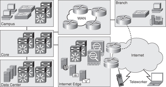
![]() Figure 1-1 illustrates at a high level a sample view of the enterprise network.
Figure 1-1 illustrates at a high level a sample view of the enterprise network.
![]() The campus, as a part of the enterprise network, is generally understood as that portion of the computing infrastructure that provides access to network communication services and resources to end users and devices spread over a single geographic location. It might span a single floor, a building, or even a large group of buildings spread over an extended geographic area. Some networks have a single campus that also acts as the core or backbone of the network and provides interconnectivity between other portions of the overall network. The campus core can often interconnect the campus access, the data center, and WAN portions of the network. In the largest enterprises, there might be multiple campus sites distributed worldwide with each providing both end-user access and local backbone connectivity. Figure 1-1 depicts the campus and the campus core as separate functional areas. Physically, the campus core is generally self contained. The campus itself may be physically spread out through an enterprise to reduce the cost of cabling. For example, it might be less expensive to aggregate switches for end-user connectivity in wiring closets dispersed throughout the enterprise.
The campus, as a part of the enterprise network, is generally understood as that portion of the computing infrastructure that provides access to network communication services and resources to end users and devices spread over a single geographic location. It might span a single floor, a building, or even a large group of buildings spread over an extended geographic area. Some networks have a single campus that also acts as the core or backbone of the network and provides interconnectivity between other portions of the overall network. The campus core can often interconnect the campus access, the data center, and WAN portions of the network. In the largest enterprises, there might be multiple campus sites distributed worldwide with each providing both end-user access and local backbone connectivity. Figure 1-1 depicts the campus and the campus core as separate functional areas. Physically, the campus core is generally self contained. The campus itself may be physically spread out through an enterprise to reduce the cost of cabling. For example, it might be less expensive to aggregate switches for end-user connectivity in wiring closets dispersed throughout the enterprise.
![]() The data center, as a part of the enterprise network, is generally understood to be a facility used to house computing systems and associated components. Examples of computing systems are servers that house mail, database, or market data applications. Historically, the data center was referred to as the server farm. Computing systems in the data center are generally used to provide services to users in the campus, such as algorithmic market data. Data center technologies are evolving quickly and imploring new technologies centered on virtualization. Nonetheless, this book focuses exclusively on the campus network of the enterprise network; consult Cisco.com for additional details about the Cisco data center architectures and technologies.
The data center, as a part of the enterprise network, is generally understood to be a facility used to house computing systems and associated components. Examples of computing systems are servers that house mail, database, or market data applications. Historically, the data center was referred to as the server farm. Computing systems in the data center are generally used to provide services to users in the campus, such as algorithmic market data. Data center technologies are evolving quickly and imploring new technologies centered on virtualization. Nonetheless, this book focuses exclusively on the campus network of the enterprise network; consult Cisco.com for additional details about the Cisco data center architectures and technologies.
| Note |
|
| Note |
|
![]() The branch/WAN portion of the enterprise network contains the routers, switches, and so on to interconnect a main office to branch offices and interconnect multiple main sites. Keep in mind, many large enterprises are composed of multiple campuses and data centers that interconnect. Often in large enterprise networks, connecting multiple enterprise data centers requires additional routing features and higher bandwidth links to interconnect remote sites. As such, Cisco designs now partition these designs into a grouping known as Data Center Interconnect (DCI). Branch/WAN and DCI are both out of scope of CCNP SWITCH and this book.
The branch/WAN portion of the enterprise network contains the routers, switches, and so on to interconnect a main office to branch offices and interconnect multiple main sites. Keep in mind, many large enterprises are composed of multiple campuses and data centers that interconnect. Often in large enterprise networks, connecting multiple enterprise data centers requires additional routing features and higher bandwidth links to interconnect remote sites. As such, Cisco designs now partition these designs into a grouping known as Data Center Interconnect (DCI). Branch/WAN and DCI are both out of scope of CCNP SWITCH and this book.
![]() Internet Edge is the portion of the enterprise network that encompasses the routers, switches, firewalls, and network devices that interconnect the enterprise network to the Internet. This section includes technology necessary to connect telecommuters from the Internet to services in the enterprise. Generally, the Internet Edge focuses heavily on network security because it connects the private enterprise to the public domain. Nonetheless, the topic of the Internet Edge as part of the enterprise network is outside the scope of this text and CCNP SWITCH.
Internet Edge is the portion of the enterprise network that encompasses the routers, switches, firewalls, and network devices that interconnect the enterprise network to the Internet. This section includes technology necessary to connect telecommuters from the Internet to services in the enterprise. Generally, the Internet Edge focuses heavily on network security because it connects the private enterprise to the public domain. Nonetheless, the topic of the Internet Edge as part of the enterprise network is outside the scope of this text and CCNP SWITCH.
![]() In review, the enterprise network is composed of four distinct areas: core backbone, campus, data center, branch/WAN, and Internet edge. These areas can have subcomponents, and additional areas can be defined in other publications or design documents. For the purpose of CCNP SWITCH and this text, focus is only the campus section of the enterprise network. The next section discusses regulatory standards that drive enterprise networks designs and models holistically, especially the data center. This section defines early information that needs gathering before designing a campus network.
In review, the enterprise network is composed of four distinct areas: core backbone, campus, data center, branch/WAN, and Internet edge. These areas can have subcomponents, and additional areas can be defined in other publications or design documents. For the purpose of CCNP SWITCH and this text, focus is only the campus section of the enterprise network. The next section discusses regulatory standards that drive enterprise networks designs and models holistically, especially the data center. This section defines early information that needs gathering before designing a campus network.
 Regulatory Standards Driving Enterprise Architectures
![]() Many regulatory standards drive enterprise architectures. Although most of these regulatory standards focus on data and information, they nonetheless drive network architectures. For example, to ensure that data is as safe as the Health Insurance Portability and Accountability Act (HIPAA) specifies, integrated security infrastructures are becoming paramount. Furthermore, the Sarbanes-Oxley Act, which specifies legal standards for maintaining the integrity of financial data, requires public companies to have multiple redundant data centers with synchronous, real-time copies of financial data.
Many regulatory standards drive enterprise architectures. Although most of these regulatory standards focus on data and information, they nonetheless drive network architectures. For example, to ensure that data is as safe as the Health Insurance Portability and Accountability Act (HIPAA) specifies, integrated security infrastructures are becoming paramount. Furthermore, the Sarbanes-Oxley Act, which specifies legal standards for maintaining the integrity of financial data, requires public companies to have multiple redundant data centers with synchronous, real-time copies of financial data.
![]() Because the purpose of this book is to focus on campus design applied to switching, additional detailed coverage of regulatory compliance with respect to design is not covered. Nevertheless, regulatory standards are important concepts for data centers, disaster recovery, and business continuance. In designing any campus network, you need to review any regulatory standards applicable to your business prior to beginning your design. Feel free to review the following regulatory compliance standards as additional reading:
Because the purpose of this book is to focus on campus design applied to switching, additional detailed coverage of regulatory compliance with respect to design is not covered. Nevertheless, regulatory standards are important concepts for data centers, disaster recovery, and business continuance. In designing any campus network, you need to review any regulatory standards applicable to your business prior to beginning your design. Feel free to review the following regulatory compliance standards as additional reading:
-
 Sarbanes-Oxley (http://www.sarbanes-oxley.com)
 -
 HIPAA (http://www.hippa.com)
 -
 SEC 17a-4, “Records to Be Preserved by Certain Exchange Members, Brokers and Dealers”
![]() Moreover, the preceding list is not an exhaustive list of regulatory standards but instead a list of starting points for reviewing compliance standards. If regulatory compliance is applicable to your enterprise, consult internally within your organization for further information about regulatory compliance before embarking on designing an enterprise network. The next section describes the motivation behind sound campus designs.
Moreover, the preceding list is not an exhaustive list of regulatory standards but instead a list of starting points for reviewing compliance standards. If regulatory compliance is applicable to your enterprise, consult internally within your organization for further information about regulatory compliance before embarking on designing an enterprise network. The next section describes the motivation behind sound campus designs.
 Campus Designs
![]() Properly designed campus architectures yield networks that are module, resilient, and flexible. In other words, properly designed campus architectures save time and money, make IT engineers’ jobs easier, and significantly increase business productivity.
Properly designed campus architectures yield networks that are module, resilient, and flexible. In other words, properly designed campus architectures save time and money, make IT engineers’ jobs easier, and significantly increase business productivity.
![]() To restate, adhering to design best-practices and design principles yield networks with the following characteristics:
To restate, adhering to design best-practices and design principles yield networks with the following characteristics:
-
 Modular: Campus network designs that are modular easily support growth and change. By using building blocks, also referred to as pods or modules, scaling the network is eased by adding new modules instead of complete redesigns.
 -
 Resilient: Campus network designs deploying best practices and proper high-availability (HA) characteristics have uptime of near 100 percent. Campus networks deployed by financial services might lose millions of dollars in revenue from a simple 1-second network outage.
 -
 Flexibility: Change in business is a guarantee for any enterprise. As such, these business changes drive campus network requirements to adapt quickly. Following campus network designs yields faster and easier changes.
![]() The next section of this text describes legacy campus designs that lead to current generation campus designs published today. This information is useful as it sets the ground work for applying current generation designs.
The next section of this text describes legacy campus designs that lead to current generation campus designs published today. This information is useful as it sets the ground work for applying current generation designs.
Legacy Campus Designs
![]() Legacy campus designs were originally based on a simple flat Layer-2 topology with a router-on-a-stick. The concept of router-on-a-stick defines a router connecting multiple LAN segments and routing between them, a legacy method of routing in campus networks.
Legacy campus designs were originally based on a simple flat Layer-2 topology with a router-on-a-stick. The concept of router-on-a-stick defines a router connecting multiple LAN segments and routing between them, a legacy method of routing in campus networks.
![]() Nevertheless, simple flat networks have many inherit limitations. Layer 2 networks are limited and do not achieve the following characteristics:
Nevertheless, simple flat networks have many inherit limitations. Layer 2 networks are limited and do not achieve the following characteristics:
-
 Scalability
 -
 Security
 -
 Modularity
 -
 Flexibility
 -
 Resiliency
 -
 High Availability
![]() A later section, “Layer 2 Switching In-Depth” provides additional information about the limitations of Layer 2 networks.
A later section, “Layer 2 Switching In-Depth” provides additional information about the limitations of Layer 2 networks.
![]() One of the original benefits of Layer 2 switching, and building Layer 2 networks, was speed. However, with the advent of high-speed switching hardware found on Cisco Catalyst and Nexus switches, Layer 3 switching performance is now equal to Layer 2 switching performance. As such, Layer 3 switching is now being deployed at scale. Examples of Cisco switches that are capable of equal Layer 2 and Layer 3 switching performance are the Catalyst 3000, 4000, and 6500 family of switches and the Nexus 7000 family of switches.
One of the original benefits of Layer 2 switching, and building Layer 2 networks, was speed. However, with the advent of high-speed switching hardware found on Cisco Catalyst and Nexus switches, Layer 3 switching performance is now equal to Layer 2 switching performance. As such, Layer 3 switching is now being deployed at scale. Examples of Cisco switches that are capable of equal Layer 2 and Layer 3 switching performance are the Catalyst 3000, 4000, and 6500 family of switches and the Nexus 7000 family of switches.
| Note |
|
| Note |
|
![]() Since Layer 3 switching performance of Cisco switches allowed for scaled networks, hierarchical designs for campus networks were developed to handle this scale effectively. The next section introduces, briefly, the hierarchical concepts in the campus. These concepts are discussed in more detail in later sections; however, a brief discussion of these topics is needed before discussing additional campus designs concepts.
Since Layer 3 switching performance of Cisco switches allowed for scaled networks, hierarchical designs for campus networks were developed to handle this scale effectively. The next section introduces, briefly, the hierarchical concepts in the campus. These concepts are discussed in more detail in later sections; however, a brief discussion of these topics is needed before discussing additional campus designs concepts.
Hierarchical Models for Campus Design
![]() Consider the Open System Interconnection (OSI) reference model, which is a layered model for understanding and implementing computer communications. By using layers, the OSI model simplifies the task required for two computers to communicate.
Consider the Open System Interconnection (OSI) reference model, which is a layered model for understanding and implementing computer communications. By using layers, the OSI model simplifies the task required for two computers to communicate.
![]() Cisco campus designs also use layers to simplify the architectures. Each layer can be focused on specific functions, thereby enabling the networking designer to choose the right systems and features for the layer. This model provides a modular framework that enables flexibility in network design and facilitates implementation and troubleshooting. The Cisco Campus Architecture fundamentally divides networks or their modular blocks into the following access, distribution, and core layers with associated characteristics:
Cisco campus designs also use layers to simplify the architectures. Each layer can be focused on specific functions, thereby enabling the networking designer to choose the right systems and features for the layer. This model provides a modular framework that enables flexibility in network design and facilitates implementation and troubleshooting. The Cisco Campus Architecture fundamentally divides networks or their modular blocks into the following access, distribution, and core layers with associated characteristics:
-
 Access layer: Used to grant the user, server, or edge device access to the network. In a campus design, the access layer generally incorporates switches with ports that provide connectivity to workstations, servers, printers, wireless access points, and so on. In the WAN environment, the access layer for telecommuters or remote sites might provide access to the corporate network across a WAN technology. The access layer is the most feature-rich section of the campus network because it is a best practice to apply features as close to the edge as possible. These features that include security, access control, filters, management, and so on are covered in later chapters.
 -
 Distribution layer: Aggregates the wiring closets, using switches to segment workgroups and isolate network problems in a campus environment. Similarly, the distribution layer aggregates WAN connections at the edge of the campus and provides a level of security. Often, the distribution layer acts as a service and control boundary between the access and core layers.
 -
 Core layer (also referred to as the backbone): A high-speed backbone, designed to switch packets as fast as possible. In current generation campus designs, the core backbone connects other switches a minimum of 10 Gigabit Ethernet. Because the core is critical for connectivity, it must provide a high level of availability and adapt to changes quickly. This layer’s design also provides for scalability and fast convergence
![]() This hierarchical model is not new and has been consistent for campus architectures for some time. In review, the hierarchical model is advantageous over nonhierarchical modes for the following reasons:
This hierarchical model is not new and has been consistent for campus architectures for some time. In review, the hierarchical model is advantageous over nonhierarchical modes for the following reasons:
-
 Provides modularity
 -
 Easier to understand
 -
 Increases flexibility
 -
 Eases growth and scalability
 -
 Provides for network predictability
 -
 Reduces troubleshooting complexity
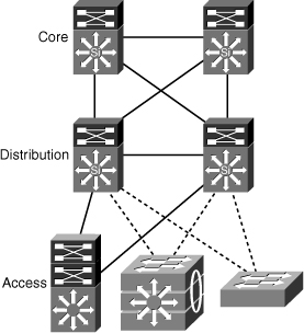
![]() Figure 1-2 illustrates the hierarchical model at a high level as applied to a modeled campus network design.
Figure 1-2 illustrates the hierarchical model at a high level as applied to a modeled campus network design.
![]() The next section discusses background information on Cisco switches and begins the discussion of the role of Cisco switches in campus network design.
The next section discusses background information on Cisco switches and begins the discussion of the role of Cisco switches in campus network design.
 Impact of Multilayer Switches on Network Design
![]() Understanding Ethernet switching is a prerequisite to building a campus network. As such, the next section reviews Layer 2 and Layer 3 terminology and concepts before discussing enterprise campus designs in subsequent sections. A subset of the material presented is a review of CCNA material.
Understanding Ethernet switching is a prerequisite to building a campus network. As such, the next section reviews Layer 2 and Layer 3 terminology and concepts before discussing enterprise campus designs in subsequent sections. A subset of the material presented is a review of CCNA material.
Ethernet Switching Review
![]() Product marketing in the networking technology field uses many terms to describe product capabilities. In many situations, product marketing stretches the use of technology terms to distinguish products among multiple vendors. One such case is the terminology of Layers 2, 3, 4, and 7 switching. These terms are generally exaggerated in the networking technology field and need careful review.
Product marketing in the networking technology field uses many terms to describe product capabilities. In many situations, product marketing stretches the use of technology terms to distinguish products among multiple vendors. One such case is the terminology of Layers 2, 3, 4, and 7 switching. These terms are generally exaggerated in the networking technology field and need careful review.
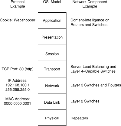
![]() The Layers 2, 3, 4, and 7 switching terminology correlates switching features to the OSI reference model. Figure 1-3 illustrates the OSI reference model and its relationship to protocols and network hardware.
The Layers 2, 3, 4, and 7 switching terminology correlates switching features to the OSI reference model. Figure 1-3 illustrates the OSI reference model and its relationship to protocols and network hardware.
![]() The next section provides a CCNA review of Layer 2 switching. Although this section is a review, it is a critical subject for later chapters.
The next section provides a CCNA review of Layer 2 switching. Although this section is a review, it is a critical subject for later chapters.
Layer 2 Switching
![]() Product marketing labeling a Cisco switch as either as a Layer 2 or as a Layer 3 switching is no longer black and white because the terminology is not consistent with product capabilities. In review, Layer 2 switches are capable of switching packets based only on MAC addresses. Layer 2 switches increase network bandwidth and port density without much complexity. The term Layer 2 switching implies that frames forwarded by the switch are not modified in any way; however, Layer 2 switches such as the Catalyst 2960 are capable of a few Layer 3 features, such as classifying packets for quality of service (QoS) and network access control based on IP address. An example of QoS marking at Layer 4 is marking the differentiated services code point (DSCP) bits in the IP header based on the TCP port number in the TCP header. Do not be concerned with understanding the QoS technology at this point as highlighted in the proceeding sentence in this chapter; this terminology is covered in more detail in later chapters. To restate, Layer 2-only switches are not capable of routing frames based on IP address and are limited to forwarding frames only based on MAC address. Nonetheless, Layer 2 switches might support features that read Layer 3 information of a frame for specific features.
Product marketing labeling a Cisco switch as either as a Layer 2 or as a Layer 3 switching is no longer black and white because the terminology is not consistent with product capabilities. In review, Layer 2 switches are capable of switching packets based only on MAC addresses. Layer 2 switches increase network bandwidth and port density without much complexity. The term Layer 2 switching implies that frames forwarded by the switch are not modified in any way; however, Layer 2 switches such as the Catalyst 2960 are capable of a few Layer 3 features, such as classifying packets for quality of service (QoS) and network access control based on IP address. An example of QoS marking at Layer 4 is marking the differentiated services code point (DSCP) bits in the IP header based on the TCP port number in the TCP header. Do not be concerned with understanding the QoS technology at this point as highlighted in the proceeding sentence in this chapter; this terminology is covered in more detail in later chapters. To restate, Layer 2-only switches are not capable of routing frames based on IP address and are limited to forwarding frames only based on MAC address. Nonetheless, Layer 2 switches might support features that read Layer 3 information of a frame for specific features.
![]() Legacy Layer 2 switches are limited in network scalability due to many factors. Consequently, all network devices on a legacy Layer 2 switch must reside on the same subnet and, as a result, exchange broadcast packets for address resolution purposes. Network devices grouped together to exchange broadcast packets constitute a broadcast domain. Layer 2 switches flood unknown unicast, multicast, and broadcast traffic throughout the entire broadcast domain. As a result, all network devices in the broadcast domain process all flooded traffic. As the size of the broadcast domain grows, its network devices become overwhelmed by the task of processing this unnecessary traffic. This caveat prevents network topologies from growing to more than a few legacy Layer 2 switches. Lack of QoS and security features are other features that can prevent the use of low-end Layer 2 switches in campus networks and data centers.
Legacy Layer 2 switches are limited in network scalability due to many factors. Consequently, all network devices on a legacy Layer 2 switch must reside on the same subnet and, as a result, exchange broadcast packets for address resolution purposes. Network devices grouped together to exchange broadcast packets constitute a broadcast domain. Layer 2 switches flood unknown unicast, multicast, and broadcast traffic throughout the entire broadcast domain. As a result, all network devices in the broadcast domain process all flooded traffic. As the size of the broadcast domain grows, its network devices become overwhelmed by the task of processing this unnecessary traffic. This caveat prevents network topologies from growing to more than a few legacy Layer 2 switches. Lack of QoS and security features are other features that can prevent the use of low-end Layer 2 switches in campus networks and data centers.
![]() However, all current and most legacy Cisco Catalyst switches support virtual LANs (VLAN), which segment traffic into separate broadcast domains and, as a result, IP subnets. VLANs overcome several of the limitations of the basic Layer 2 networks, as discussed in the previous paragraph. This book discusses VLANs in more detail in the next chapter.
However, all current and most legacy Cisco Catalyst switches support virtual LANs (VLAN), which segment traffic into separate broadcast domains and, as a result, IP subnets. VLANs overcome several of the limitations of the basic Layer 2 networks, as discussed in the previous paragraph. This book discusses VLANs in more detail in the next chapter.
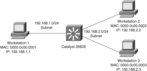
![]() Figure 1-4 illustrates an example of a Layer 2 switch with workstations attached. Because the switch is only capable of MAC address forwarding, the workstations must reside on the same subnet to communicate.
Figure 1-4 illustrates an example of a Layer 2 switch with workstations attached. Because the switch is only capable of MAC address forwarding, the workstations must reside on the same subnet to communicate.
Layer 3 Switching
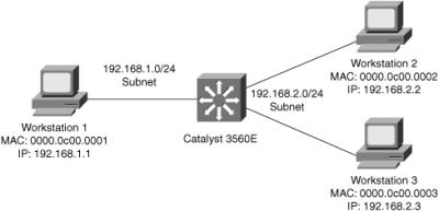
![]() Layer 3 switches include Layer 3 routing capabilities. Many of the current-generation Catalyst Layer 3 switches can use routing protocols such as BGP, RIP, OSPF, and EIGRP to make optimal forwarding decisions. A few Cisco switches that support routing protocols do not support BGP because they do not have the memory necessary for large routing tables. These routing protocols are reviewed in later chapters. Figure 1-5 illustrates a Layer 3 switch with several workstations attached. In this example, the Layer 3 switch routes packets between the two subnets.
Layer 3 switches include Layer 3 routing capabilities. Many of the current-generation Catalyst Layer 3 switches can use routing protocols such as BGP, RIP, OSPF, and EIGRP to make optimal forwarding decisions. A few Cisco switches that support routing protocols do not support BGP because they do not have the memory necessary for large routing tables. These routing protocols are reviewed in later chapters. Figure 1-5 illustrates a Layer 3 switch with several workstations attached. In this example, the Layer 3 switch routes packets between the two subnets.
| Note |
|
Layer 4 and Layer 7 Switching
![]() Layers 4 and 7 switching terminology is not as straightforward as Layers 2 and 3 switching terminology. Layer 4 switching implies switching based on protocol sessions. In other words, Layer 4 switching uses not only source and destination IP addresses in switching decisions, but also IP session information contained in the TCP and User Datagram Protocol (UDP) portions of the packet. The most common method of distinguishing traffic with Layer 4 switching is to use the TCP and UDP port numbers. Server load balancing, a Layer 4 to Layer 7 switching feature, can use TCP information such as TCP SYN, FIN, and RST to make forwarding decisions. (Refer to RFC 793 for explanations of TCP SYN, FIN, and RST.) As a result, Layer 4 switches can distinguish different types of IP traffic flows, such as differentiating the FTP, Network Time Protocol (NTP), HTTP, Secure HTTP (S-HTTP), and Secure Shell (SSH) traffic.
Layers 4 and 7 switching terminology is not as straightforward as Layers 2 and 3 switching terminology. Layer 4 switching implies switching based on protocol sessions. In other words, Layer 4 switching uses not only source and destination IP addresses in switching decisions, but also IP session information contained in the TCP and User Datagram Protocol (UDP) portions of the packet. The most common method of distinguishing traffic with Layer 4 switching is to use the TCP and UDP port numbers. Server load balancing, a Layer 4 to Layer 7 switching feature, can use TCP information such as TCP SYN, FIN, and RST to make forwarding decisions. (Refer to RFC 793 for explanations of TCP SYN, FIN, and RST.) As a result, Layer 4 switches can distinguish different types of IP traffic flows, such as differentiating the FTP, Network Time Protocol (NTP), HTTP, Secure HTTP (S-HTTP), and Secure Shell (SSH) traffic.
![]() Layer 7 switching is switching based on application information. Layer 7 switching capability implies content-intelligence. Content-intelligence with respect to web browsing implies features such as inspection of URLs, cookies, host headers, and so on. Content-intelligence with respect to VoIP can include distinguishing call destinations such as local or long distance.
Layer 7 switching is switching based on application information. Layer 7 switching capability implies content-intelligence. Content-intelligence with respect to web browsing implies features such as inspection of URLs, cookies, host headers, and so on. Content-intelligence with respect to VoIP can include distinguishing call destinations such as local or long distance.
![]() Table 1-1 summarizes the layers of the OSI model with their respective protocol data units (PDU), which represent the data exchanged at each layer. Note the difference between frames and packets and their associated OSI level. The table also contains a column illustrating sample device types operating at the specified layer.
Table 1-1 summarizes the layers of the OSI model with their respective protocol data units (PDU), which represent the data exchanged at each layer. Note the difference between frames and packets and their associated OSI level. The table also contains a column illustrating sample device types operating at the specified layer.
|
|
|
|
|
|
|---|---|---|---|---|
|
|
|
|
|
|
|
|
|
|
|
|
|
|
|
|
|
|
|
|
|
|
|
|
|
|
|
|
|
|
 Layer 2 Switching In-Depth
![]() Layer 2 switching is also referred to as hardware-based bridging. In a Layer 2-only switch, ASICs handle frame forwarding. Moreover, Layer 2 switches deliver the ability to increase bandwidth to the wiring closet without adding unnecessary complexity to the network. At Layer 2, no modification is required to the frame content when going between Layer 1 interfaces, such as Fast Ethernet to 10 Gigabit Ethernet.
Layer 2 switching is also referred to as hardware-based bridging. In a Layer 2-only switch, ASICs handle frame forwarding. Moreover, Layer 2 switches deliver the ability to increase bandwidth to the wiring closet without adding unnecessary complexity to the network. At Layer 2, no modification is required to the frame content when going between Layer 1 interfaces, such as Fast Ethernet to 10 Gigabit Ethernet.
![]() In review, the network design properties of current-generation Layer 2 switches include the following:
In review, the network design properties of current-generation Layer 2 switches include the following:
-
 Designed for near wire-speed performance
 -
 Built using high-speed, specialized ASICs
 -
 Switches at low latency
 -
 Scalable to a several switch topology without a router or Layer 3 switch
 -
 Supports Layer 3 functionality such as Internet Group Management Protocol (IGMP) snooping and QoS marking
 -
 Offers limited scalability in large networks without Layer 3 boundaries
 Layer 3 Switching In-Depth
![]() Layer 3 switching is hardware-based routing. Layer 3 switches overcome the inadequacies of Layer 2 scalability by providing routing domains. The packet forwarding in Layer 3 switches is handled by ASICs and other specialized circuitry. A Layer 3 switch performs everything on a packet that a traditional router does, including the following:
Layer 3 switching is hardware-based routing. Layer 3 switches overcome the inadequacies of Layer 2 scalability by providing routing domains. The packet forwarding in Layer 3 switches is handled by ASICs and other specialized circuitry. A Layer 3 switch performs everything on a packet that a traditional router does, including the following:
-
 Determines the forwarding path based on Layer 3 information
 -
 Validates the integrity of the Layer 3 packet header via the Layer 3 checksum
 -
 Verifies and decrements packet Time-To-Live (TTL) expiration
 -
 Rewrites the source and destination MAC address during IP rewrites
 -
 Updates Layer 2 CRC during Layer 3 rewrite
 -
 Processes and responds to any option information in the packet such as the Internet Control Message Protocol (ICMP) record
 -
 Updates forwarding statistics for network management applications
 -
 Applies security controls and classification of service if required
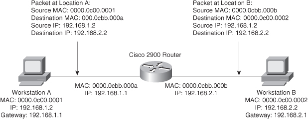
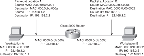
![]() Layer 3 routing requires the ability of packet rewriting. Packet rewriting occurs on any routed boundary. Figure 1-6 illustrates the basic packet rewriting requirements of Layer 3 routing in an example in which two workstations are communicating using ICMP.
Layer 3 routing requires the ability of packet rewriting. Packet rewriting occurs on any routed boundary. Figure 1-6 illustrates the basic packet rewriting requirements of Layer 3 routing in an example in which two workstations are communicating using ICMP.
![]() Address Resolution Protocol (ARP) plays an important role in Layer 3 packet rewriting. When Workstation A in Figure 1-6 sends five ICMP echo requests to Workstation B, the following events occur (assuming all the devices in this example have yet to communicate, use static addressing versus DHCP, and there is no event to trigger a gratuitous ARP):
Address Resolution Protocol (ARP) plays an important role in Layer 3 packet rewriting. When Workstation A in Figure 1-6 sends five ICMP echo requests to Workstation B, the following events occur (assuming all the devices in this example have yet to communicate, use static addressing versus DHCP, and there is no event to trigger a gratuitous ARP):
-
 Workstation A sends an ARP request for its default gateway. Workstation A sends this ARP to obtain the MAC address of the default gateway. Without knowing the MAC address of the default gateway, Workstation A cannot send any traffic outside the local subnet. Note that, in this example, Workstation A’s default gateway is the Cisco 2900 router with two Ethernet interfaces.
 -
 The default gateway, the Cisco 2900, responds to the ARP request with an ARP reply, sent to the unicast MAC address and IP address of Workstation A, indicating the default gateway’s MAC address. The default gateway also adds an ARP entry for Workstation A in its ARP table upon receiving the ARP request.
 -
 Workstation A sends the first ICMP echo request to the destination IP address of Workstation B with a destination MAC address of the default gateway.
 -
 The router receives the ICMP echo request and determines the shortest path to the destination IP address.
 -
 Because the default gateway does not have an ARP entry for the destination IP address, Workstation B, the default gateway drops the first ICMP echo request from Workstation A. The default gateway drops packets in the absence of ARP entries to avoid storing packets that are destined for devices without ARP entries as defined by the original RFCs governing ARP.
 -
 The default gateway sends an ARP request to Workstation B to get Workstation B’s MAC address.
 -
 Upon receiving the ARP request, Workstation B sends an ARP response with its MAC address.
 -
 By this time, Workstation A is sending a second ICMP echo request to the destination IP of Workstation B via its default gateway.
 -
 Upon receipt of the second ICMP echo request, the default gateway now has an ARP entry for Workstation B. The default gateway in turn rewrites the source MAC address to itself and the destination MAC to Workstation B’s MAC address, and then forwards the frame to Workstation B.
 -
 Workstation B receives the ICMP echo request and sends an ICMP echo reply to the IP address of Workstation A with the destination MAC address of the default gateway.
![]() Figure 1-6 illustrates the Layer 2 and Layer 3 rewriting at different places along the path between Workstation A and B. This figure and example illustrate the fundamental operation of Layer 3 routing and switching.
Figure 1-6 illustrates the Layer 2 and Layer 3 rewriting at different places along the path between Workstation A and B. This figure and example illustrate the fundamental operation of Layer 3 routing and switching.
![]() The primary difference between the packet-forwarding operation of a router and Layer 3 switching is the physical implementation. Layer 3 switches use different hardware components and have greater port density than traditional routers.
The primary difference between the packet-forwarding operation of a router and Layer 3 switching is the physical implementation. Layer 3 switches use different hardware components and have greater port density than traditional routers.
![]() These concepts of Layer 2 switching, Layer 3 forwarding, and Layer 3 switching are applied in a single platform: the multilayer switch. Because it is designed to handle high-performance LAN traffic, a Layer 3 switch is locatable when there is a need for a router and a switch within the network, cost effectively replacing the traditional router and router-on-a-stick designs of the past.
These concepts of Layer 2 switching, Layer 3 forwarding, and Layer 3 switching are applied in a single platform: the multilayer switch. Because it is designed to handle high-performance LAN traffic, a Layer 3 switch is locatable when there is a need for a router and a switch within the network, cost effectively replacing the traditional router and router-on-a-stick designs of the past.
 Understanding Multilayer Switching
![]() Multilayer switching combines Layer 2 switching and Layer 3 routing functionality. Generally, the networking field uses the terms Layer 3 switch and multilayer switch interchangeably to describe a switch that is capable of Layer 2 and Layer 3 switching. In specific terms, multilayer switches move campus traffic at wire speed while satisfying Layer 3 connectivity requirements. This combination not only solves throughput problems but also helps to remove the conditions under which Layer 3 bottlenecks form. Moreover, multilayer switches support many other Layer 2 and Layer 3 features besides routing and switching. For example, many multilayer switches support QoS marking. Combining both Layer 2 and Layer 3 functionality and features allows for ease of deployment and simplified network topologies.
Multilayer switching combines Layer 2 switching and Layer 3 routing functionality. Generally, the networking field uses the terms Layer 3 switch and multilayer switch interchangeably to describe a switch that is capable of Layer 2 and Layer 3 switching. In specific terms, multilayer switches move campus traffic at wire speed while satisfying Layer 3 connectivity requirements. This combination not only solves throughput problems but also helps to remove the conditions under which Layer 3 bottlenecks form. Moreover, multilayer switches support many other Layer 2 and Layer 3 features besides routing and switching. For example, many multilayer switches support QoS marking. Combining both Layer 2 and Layer 3 functionality and features allows for ease of deployment and simplified network topologies.
![]() Moreover, Layer 3 switches limit the scale of spanning tree by segmenting Layer 2, which eases network complexity. In addition, Layer 3 routing protocols enable load-balancing, fast convergence, scalability, and control compared to traditional Layer 2 features.
Moreover, Layer 3 switches limit the scale of spanning tree by segmenting Layer 2, which eases network complexity. In addition, Layer 3 routing protocols enable load-balancing, fast convergence, scalability, and control compared to traditional Layer 2 features.
![]() In review, multilayer switching is a marketing term used to refer to any Cisco switch capable of Layer 2 switching and Layer 3 routing. From a design perspective, all enterprise campus designs include multilayer switches in some aspect, most likely in the core or distribution layers. Moreover, some campus designs are evolving to include an option for designing Layer 3 switching all the way to the access layer with a future option of supporting Layer 3 network ports on each individual access port. Over the next few years, the trend in the campus is to move to a pure Layer 3 environment consisting of inexpensive Layer 3 switches.
In review, multilayer switching is a marketing term used to refer to any Cisco switch capable of Layer 2 switching and Layer 3 routing. From a design perspective, all enterprise campus designs include multilayer switches in some aspect, most likely in the core or distribution layers. Moreover, some campus designs are evolving to include an option for designing Layer 3 switching all the way to the access layer with a future option of supporting Layer 3 network ports on each individual access port. Over the next few years, the trend in the campus is to move to a pure Layer 3 environment consisting of inexpensive Layer 3 switches.
| Note |
|
 Introduction to Cisco Switches
![]() Cisco has a plethora of Layer 2 and Layer 3 switch models. For brevity, this section highlights a few popular models used in the campus, core backbone, and data center. For a complete list of Cisco switches, consult product documentation at Cisco.com.
Cisco has a plethora of Layer 2 and Layer 3 switch models. For brevity, this section highlights a few popular models used in the campus, core backbone, and data center. For a complete list of Cisco switches, consult product documentation at Cisco.com.
Cisco Catalyst 6500 Family of Switches
![]() The Cisco Catalyst 6500 family of switches are the most popular switches Cisco ever produced. They are found in a wide variety of installs not only including campus, data center, and backbone, but also found in deployment of services, WAN, branch, and so on in both enterprise and service provider networks. For the purpose of CCNP SWITCH and the scope of this book, the Cisco Catalyst 6500 family of switches are summarized as follows:
The Cisco Catalyst 6500 family of switches are the most popular switches Cisco ever produced. They are found in a wide variety of installs not only including campus, data center, and backbone, but also found in deployment of services, WAN, branch, and so on in both enterprise and service provider networks. For the purpose of CCNP SWITCH and the scope of this book, the Cisco Catalyst 6500 family of switches are summarized as follows:
-
 Scalable modular switch up to 13 slots
 -
 Supports up to 16 10-Gigabit Ethernet interfaces per slot in an over-subscription model
 -
 Up to 80 Gbps of bandwidth per slot in current generation hardware
 -
 Supports Cisco IOS with a plethora of Layer 2 and Layer 3 switching features
 -
 Optionally supports up to Layer 7 features with specialized modules
 -
 Integrated redundant and high-available power supplies, fans, and supervisor engineers
 -
 Supports Layer 3 Non-Stop Forwarding (NSF) whereby routing peers are maintained during a supervisor switchover.
 -
 Backward capability and investment protection have lead to a long life cycle
Cisco Catalyst 4500 Family of Switches
![]() The Cisco Catalyst 4500 family of switches is a vastly popular modular switch found in many campus networks at the distribution layer or in collapsed core networks of small to medium-sized networks. Collapsed core designs combine the core and distribution layers into a single area. The Catalyst 4500 is one step down from the Catalyst 6500 but does support a wide array of Layer 2 and Layer 3 features. In summary, the Cisco Catalyst 4500 family of switches are summarized as follows:
The Cisco Catalyst 4500 family of switches is a vastly popular modular switch found in many campus networks at the distribution layer or in collapsed core networks of small to medium-sized networks. Collapsed core designs combine the core and distribution layers into a single area. The Catalyst 4500 is one step down from the Catalyst 6500 but does support a wide array of Layer 2 and Layer 3 features. In summary, the Cisco Catalyst 4500 family of switches are summarized as follows:
Cisco Catalyst 4948G, 3750, and 3560 Family of Switches
![]() The Cisco Catalyst 4948G, 3750, and 3560 family of switches are popular switches used in campus networks for fixed-port scenarios, most often the access layer. These switches are summarized as follows:
The Cisco Catalyst 4948G, 3750, and 3560 family of switches are popular switches used in campus networks for fixed-port scenarios, most often the access layer. These switches are summarized as follows:
-
 Available in a variety of fixed port configurations with up to 48 1-Gbps access layer ports and 4 10-Gigabit Ethernet interfaces for uplinks to distribution layer
 -
 Supports Cisco IOS
 -
 Supports both Layer 2 and Layer 3 switching
 -
 Not architected with redundant hardware
Cisco Catalyst 2000 Family of Switches
![]() The Cisco Catalyst 2000 family of switches are Layer 2-only switches capable of few Layer 3 features aside from Layer 3 routing. These features are often found in the access layer in campus networks. These switches are summarized as follows:
The Cisco Catalyst 2000 family of switches are Layer 2-only switches capable of few Layer 3 features aside from Layer 3 routing. These features are often found in the access layer in campus networks. These switches are summarized as follows:
-
 Available in a variety of fixed port configurations with up to 48 1-Gbps access layer ports and multiple 10-Gigabit Ethernet uplinks
 -
 Supports Cisco IOS
 -
 Supports only Layer 2 switching
 -
 Not architected with redundant hardware
Nexus 7000 Family of Switches
![]() The Nexus 7000 family of switches are the Cisco premier data center switches. The product launch in 2008; and thus, the Nexus 7000 software does not support all the features of Cisco IOS yet. Nonetheless, the Nexus 7000 is summarized as follows:
The Nexus 7000 family of switches are the Cisco premier data center switches. The product launch in 2008; and thus, the Nexus 7000 software does not support all the features of Cisco IOS yet. Nonetheless, the Nexus 7000 is summarized as follows:
Nexus 5000 and 2000 Family of Switches
![]() The Nexus 5000 and 2000 family of switches are low-latency switches designed for deployment in the access layer of the data center. These switches are Layer 2-only switches today but support cut-through switching for low latency. The Nexus 5000 switches are designed for 10-Gigabit Ethernet applications and also support Fibre Channel over Ethernet (FCOE).
The Nexus 5000 and 2000 family of switches are low-latency switches designed for deployment in the access layer of the data center. These switches are Layer 2-only switches today but support cut-through switching for low latency. The Nexus 5000 switches are designed for 10-Gigabit Ethernet applications and also support Fibre Channel over Ethernet (FCOE).
 Hardware and Software-Switching Terminology
![]() This book refers to the terms hardware-switching and software-switching regularly throughout the text. The industry term hardware-switching refers to the act of processing packets at any Layers 2 through 7, via specialized hardware components referred to as application-specific integrated circuits (ASIC). ASICs can generally reach throughput at wire speed without performance degradation for advanced features such as QoS marking, ACL processing, or IP rewriting.
This book refers to the terms hardware-switching and software-switching regularly throughout the text. The industry term hardware-switching refers to the act of processing packets at any Layers 2 through 7, via specialized hardware components referred to as application-specific integrated circuits (ASIC). ASICs can generally reach throughput at wire speed without performance degradation for advanced features such as QoS marking, ACL processing, or IP rewriting.
| Note |
|
![]() Switching and routing traffic via hardware-switching is considerably faster than the traditional software-switching of frames via a CPU. Many ASICs, especially ASICs for Layer 3 routing, use specialized memory referred to as ternary content addressable memory (TCAM) along with packet-matching algorithms to achieve high performance, whereas CPUs simply use higher processing rates to achieve greater degrees of performance. Generally, ASICs can achieve higher performance and availability than CPUs. In addition, ASICs scale easily in switching architecture, whereas CPUs do not. ASICs integrate not only on Supervisor Engines, but also on individual line modules of Catalyst switches to hardware-switch packets in a distributed manner.
Switching and routing traffic via hardware-switching is considerably faster than the traditional software-switching of frames via a CPU. Many ASICs, especially ASICs for Layer 3 routing, use specialized memory referred to as ternary content addressable memory (TCAM) along with packet-matching algorithms to achieve high performance, whereas CPUs simply use higher processing rates to achieve greater degrees of performance. Generally, ASICs can achieve higher performance and availability than CPUs. In addition, ASICs scale easily in switching architecture, whereas CPUs do not. ASICs integrate not only on Supervisor Engines, but also on individual line modules of Catalyst switches to hardware-switch packets in a distributed manner.
![]() ASICs do have memory limitations. For example, the Catalyst 6500 family of switches can accommodate ACLs with a larger number of entries compared to the Catalyst 3560E family of switches due to the larger ASIC memory on the Catalyst 6500 family of switches. Generally, the size of the ASIC memory is relative to the cost and application of the switch. Furthermore, ASICs do not support all the features of the traditional Cisco IOS. For instance, the Catalyst 6500 family of switches with a Supervisor Engine 720 and an MSFC3 (Multilayer Switch Feature Card) must software-switch all packets requiring Network Address Translation (NAT) without the use of specialized line modules. As products continue to evolve and memory becomes cheaper, ASICs gain additional memory and feature support.
ASICs do have memory limitations. For example, the Catalyst 6500 family of switches can accommodate ACLs with a larger number of entries compared to the Catalyst 3560E family of switches due to the larger ASIC memory on the Catalyst 6500 family of switches. Generally, the size of the ASIC memory is relative to the cost and application of the switch. Furthermore, ASICs do not support all the features of the traditional Cisco IOS. For instance, the Catalyst 6500 family of switches with a Supervisor Engine 720 and an MSFC3 (Multilayer Switch Feature Card) must software-switch all packets requiring Network Address Translation (NAT) without the use of specialized line modules. As products continue to evolve and memory becomes cheaper, ASICs gain additional memory and feature support.
![]() For the purpose of CCNP SWITCH and campus network design, the concepts in this section are overly simplified. Use the content in this section as information for sections that refer to the terminology. The next section changes scope from switching hardware and technology to campus network types.
For the purpose of CCNP SWITCH and campus network design, the concepts in this section are overly simplified. Use the content in this section as information for sections that refer to the terminology. The next section changes scope from switching hardware and technology to campus network types.
 Campus Network Traffic Types
![]() Campus designs are significantly tied to network size. However, traffic patterns and traffic types through each layer hold significant importance on how to shape a campus design. Each type of traffic represents specific needs in terms of bandwidth and flow patterns. Table 1-2 lists several different types of traffic that might exist on a campus network. As such, indentifying traffic flows, types, and patterns is a prerequisite to designing a campus network.
Campus designs are significantly tied to network size. However, traffic patterns and traffic types through each layer hold significant importance on how to shape a campus design. Each type of traffic represents specific needs in terms of bandwidth and flow patterns. Table 1-2 lists several different types of traffic that might exist on a campus network. As such, indentifying traffic flows, types, and patterns is a prerequisite to designing a campus network.
![]() Table 1-2 highlights common traffic types with a description, common flow patterns, and a denotation of bandwidth (BW). The BW column highlights on a scale of low to very high the common rate of traffic for the corresponding traffic type for comparison purposes. Note: This table illustrates common traffic types and common characteristics; it is not uncommon to find scenarios of atypical traffic types.
Table 1-2 highlights common traffic types with a description, common flow patterns, and a denotation of bandwidth (BW). The BW column highlights on a scale of low to very high the common rate of traffic for the corresponding traffic type for comparison purposes. Note: This table illustrates common traffic types and common characteristics; it is not uncommon to find scenarios of atypical traffic types.
![]() For the purpose of enterprise campus design, note the traffic types in your network, particularly multicast traffic. Multicast traffic for servers-centric applications is generally restricted to the data center; however, whatever multicast traffics spans into the campus needs to be accounted for because it can significantly drive campus design. The next sections delve into several types of applications in more detail and their traffic flow characteristics.
For the purpose of enterprise campus design, note the traffic types in your network, particularly multicast traffic. Multicast traffic for servers-centric applications is generally restricted to the data center; however, whatever multicast traffics spans into the campus needs to be accounted for because it can significantly drive campus design. The next sections delve into several types of applications in more detail and their traffic flow characteristics.
| Note |
|
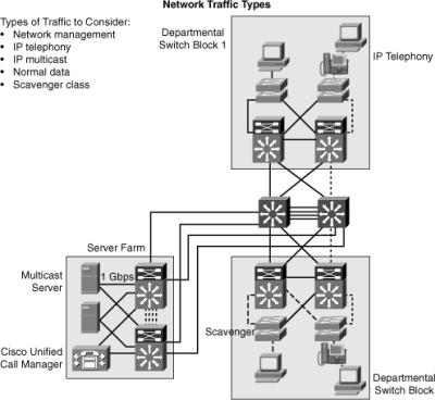
![]() Figure 1-7 illustrates a sample enterprise network with several traffic patterns highlighted as dotted lines to represent possible interconnects that might experience heavy traffic utilization.
Figure 1-7 illustrates a sample enterprise network with several traffic patterns highlighted as dotted lines to represent possible interconnects that might experience heavy traffic utilization.
Peer-to-Peer Applications
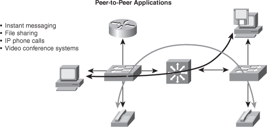
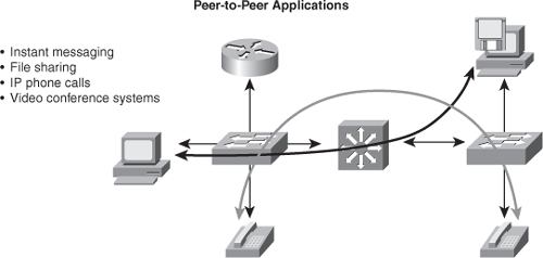
![]() Some traffic flows are based on a peer-to-peer model, where traffic flows between endpoints that may be far from each other. Peer-to-peer applications include applications where the majority of network traffic passes from one end device, such as a PC or IP phone, to another through the organizational network. (See Figure 1-8.) Some traffic flows are not sensitive to bandwidth and delay issues, whereas some others require real-time interaction between peer devices. Typical peer-to-peer applications include the following:
Some traffic flows are based on a peer-to-peer model, where traffic flows between endpoints that may be far from each other. Peer-to-peer applications include applications where the majority of network traffic passes from one end device, such as a PC or IP phone, to another through the organizational network. (See Figure 1-8.) Some traffic flows are not sensitive to bandwidth and delay issues, whereas some others require real-time interaction between peer devices. Typical peer-to-peer applications include the following:
-
 Instant messaging: Two peers establish communication between two end systems. When the connection is established, the conversation is direct.
 -
 File sharing: Some operating systems or applications require direct access to data on other workstations. Fortunately, most enterprises are banning such applications because they lack centralized or network-administered security.
 -
 IP phone calls: The network requirements of IP phone calls are strict because of the need for QoS treatment to minimize jitter.
 -
 Video conference systems: The network requirements of video conferencing are demanding because of the bandwidth consumption and class of service (CoS) requirements.
Client/Server Applications
![]() Many enterprise traffic flows are based on a client/server model, where connections to the server might become bottlenecks. Network bandwidth used to be costly, but today, it is cost-effective compared to the application requirements. For example, the cost of Gigabit Ethernet and 10 Gigabit is advantageous compared to application bandwidth requirements that rarely exceed 1 Gigabit Ethernet. Moreover, because the switch delay is insignificant for most client/server applications with high-performance Layer 3 switches, locating the servers centrally rather than in the workgroup is technically feasible and reduces support costs. Latency is extremely important to financial and market data applications, such as 29 West and Tibco. For situations in which the lowest latency is necessary, Cisco offers low-latency modules for the Nexus 7000 family of switches and the Nexus 5000 and 2000 that are low-latency for all variants. For the purpose of this book and CCNP SWITCH, the important take-away is that data center applications for financials and market trade can require a low latency switch, such as the Nexus 5000 family of switches.
Many enterprise traffic flows are based on a client/server model, where connections to the server might become bottlenecks. Network bandwidth used to be costly, but today, it is cost-effective compared to the application requirements. For example, the cost of Gigabit Ethernet and 10 Gigabit is advantageous compared to application bandwidth requirements that rarely exceed 1 Gigabit Ethernet. Moreover, because the switch delay is insignificant for most client/server applications with high-performance Layer 3 switches, locating the servers centrally rather than in the workgroup is technically feasible and reduces support costs. Latency is extremely important to financial and market data applications, such as 29 West and Tibco. For situations in which the lowest latency is necessary, Cisco offers low-latency modules for the Nexus 7000 family of switches and the Nexus 5000 and 2000 that are low-latency for all variants. For the purpose of this book and CCNP SWITCH, the important take-away is that data center applications for financials and market trade can require a low latency switch, such as the Nexus 5000 family of switches.
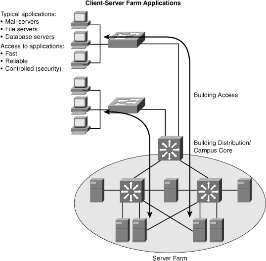
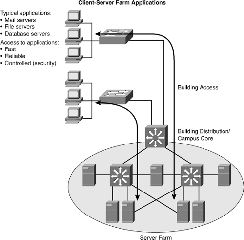
![]() Figure 1-9 depicts, at a high level, client/server application traffic flow.
Figure 1-9 depicts, at a high level, client/server application traffic flow.
![]() In large enterprises, the application traffic might cross more than one wiring closet or LAN to access applications to a server group in a data center. Client-server farm applications apply the 20/80 rule, in which only 20 percent of the traffic remains on the local LAN segment, and 80 percent leaves the segment to reach centralized servers, the Internet, and so on. Client-server farm applications include the following:
In large enterprises, the application traffic might cross more than one wiring closet or LAN to access applications to a server group in a data center. Client-server farm applications apply the 20/80 rule, in which only 20 percent of the traffic remains on the local LAN segment, and 80 percent leaves the segment to reach centralized servers, the Internet, and so on. Client-server farm applications include the following:
-
 Common file servers
 -
 Common database servers for organizational applications such as human resource, inventory, or sales applications
![]() Users of large enterprises require fast, reliable, and controlled access to critical applications. For example, traders need access to trading applications anytime with good response times to be competitive with other traders. To fulfill these demands and keep administrative costs low, the solution is to place the servers in a common server farm in a data center. The use of server farms in data centers requires a network infrastructure that is highly resilient and redundant and that provides adequate throughput. Typically, high-end LAN switches with the fastest LAN technologies, such as 10 Gigabit Ethernet, are deployed. For Cisco switches, the current trend is to deploy Nexus switches while the campus deploys Catalyst switches. The use of the Catalyst switches in the campus and Nexus in the data center is a market transition from earlier models that used Catalyst switches throughout the enterprise. At the time of publication, Nexus switches do not run the traditional Cisco IOS found on Cisco routers and switch. Instead, these switches run Nexus OS (NX-OS), which was derived from SAN-OS found on the Cisco MDS SAN platforms.
Users of large enterprises require fast, reliable, and controlled access to critical applications. For example, traders need access to trading applications anytime with good response times to be competitive with other traders. To fulfill these demands and keep administrative costs low, the solution is to place the servers in a common server farm in a data center. The use of server farms in data centers requires a network infrastructure that is highly resilient and redundant and that provides adequate throughput. Typically, high-end LAN switches with the fastest LAN technologies, such as 10 Gigabit Ethernet, are deployed. For Cisco switches, the current trend is to deploy Nexus switches while the campus deploys Catalyst switches. The use of the Catalyst switches in the campus and Nexus in the data center is a market transition from earlier models that used Catalyst switches throughout the enterprise. At the time of publication, Nexus switches do not run the traditional Cisco IOS found on Cisco routers and switch. Instead, these switches run Nexus OS (NX-OS), which was derived from SAN-OS found on the Cisco MDS SAN platforms.
![]() Nexus switches have a higher cost than Catalyst switches and do not support telephony, inline power, firewall, or load-balancing services, and so on. However, Nexus switches do support higher throughput, lower latency, high-availability, and high-density 10-Gigabit Ethernet suited for data center environments. A later section details the Cisco switches with more information.
Nexus switches have a higher cost than Catalyst switches and do not support telephony, inline power, firewall, or load-balancing services, and so on. However, Nexus switches do support higher throughput, lower latency, high-availability, and high-density 10-Gigabit Ethernet suited for data center environments. A later section details the Cisco switches with more information.
Client-Enterprise Edge Applications
![]() Client-enterprise edge applications use servers on the enterprise edge to exchange data between the organization and its public servers. Examples of these applications include external mail servers and public web servers.
Client-enterprise edge applications use servers on the enterprise edge to exchange data between the organization and its public servers. Examples of these applications include external mail servers and public web servers.
![]() The most important communication issues between the campus network and the enterprise edge are security and high availability. An application that is installed on the enterprise edge might be crucial to organizational process flow; therefore, outages can result in increased process cost.
The most important communication issues between the campus network and the enterprise edge are security and high availability. An application that is installed on the enterprise edge might be crucial to organizational process flow; therefore, outages can result in increased process cost.
![]() The organizations that support their partnerships through e-commerce applications also place their e-commerce servers in the enterprise edge. Communications with the servers located on the campus network are vital because of two-way data replication. As a result, high redundancy and resiliency of the network are important requirements for these applications.
The organizations that support their partnerships through e-commerce applications also place their e-commerce servers in the enterprise edge. Communications with the servers located on the campus network are vital because of two-way data replication. As a result, high redundancy and resiliency of the network are important requirements for these applications.
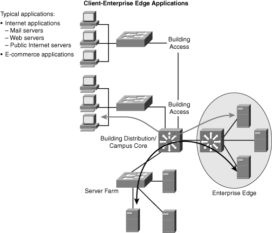
![]() Figure 1-10 illustrates traffic flow for a sample client-enterprise edge application with connections through the Internet.
Figure 1-10 illustrates traffic flow for a sample client-enterprise edge application with connections through the Internet.
![]() Recall from earlier sections that the client-enterprise edge applications in Figure 1-10 pass traffic through the Internet edge portion of the Enterprise network.
Recall from earlier sections that the client-enterprise edge applications in Figure 1-10 pass traffic through the Internet edge portion of the Enterprise network.
![]() In review, understanding traffic flow and patterns of an enterprise are necessary prior to designing a campus network. This traffic flow and pattern ultimately shapes scale, features, and use of Cisco switches in the campus network. Before further discussion on designing campus networks, the next section highlights two Cisco network architecture models that are useful in understanding all the elements that make a successful network deployment.
In review, understanding traffic flow and patterns of an enterprise are necessary prior to designing a campus network. This traffic flow and pattern ultimately shapes scale, features, and use of Cisco switches in the campus network. Before further discussion on designing campus networks, the next section highlights two Cisco network architecture models that are useful in understanding all the elements that make a successful network deployment.




0 comments
Post a Comment