| Note |
|
 Designing an IP Addressing Plan
![]() This section explores private and public address types, how to determine the size of the network in relation to the addressing plan, and how to plan an IP addressing hierarchy. The section concludes with a discussion of various IP address assignment and name resolution methods.
This section explores private and public address types, how to determine the size of the network in relation to the addressing plan, and how to plan an IP addressing hierarchy. The section concludes with a discussion of various IP address assignment and name resolution methods.
| Note |
|
 Private and Public IPv4 Addresses
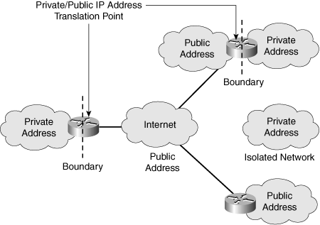
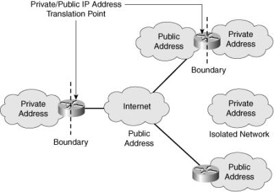
![]() Recall from Chapter 1 that the IP address space is divided into public and private spaces. Private addresses are reserved IP addresses that are to be used only internally within a company’s network, not on the Internet. Private addresses must therefore be mapped to a company’s external registered address when sending anything on the Internet. Public IP addresses are provided for external communication. Figure 6-1 illustrates the use of private and public addresses in a network.
Recall from Chapter 1 that the IP address space is divided into public and private spaces. Private addresses are reserved IP addresses that are to be used only internally within a company’s network, not on the Internet. Private addresses must therefore be mapped to a company’s external registered address when sending anything on the Internet. Public IP addresses are provided for external communication. Figure 6-1 illustrates the use of private and public addresses in a network.
![]() RFC 1918, Address Allocation for Private Internets, defines the private IP addresses as follows:
RFC 1918, Address Allocation for Private Internets, defines the private IP addresses as follows:
-
 10.0.0.0 to 10.255.255.255
 -
 172.16.0.0 to 172.31.255.255
 -
 192.168.0.0 to 192.168.255.255
![]() The remaining addresses are public addresses.
The remaining addresses are public addresses.
Private Versus Public Address Selection Criteria
![]() Very few public IP addresses are currently available, so Internet service providers (ISPs) can assign only a subset of Class C addresses to their customers. Therefore, in most cases, the number of public IP addresses assigned to an organization is inadequate for addressing their entire network.
Very few public IP addresses are currently available, so Internet service providers (ISPs) can assign only a subset of Class C addresses to their customers. Therefore, in most cases, the number of public IP addresses assigned to an organization is inadequate for addressing their entire network.
![]() The solution to this problem is to use private IP addresses within a network and to translate these private addresses to public addresses when Internet connectivity is required. When selecting addresses, the network designer should consider the following questions:
The solution to this problem is to use private IP addresses within a network and to translate these private addresses to public addresses when Internet connectivity is required. When selecting addresses, the network designer should consider the following questions:
-
 Are private, public, or both IP address types required?
 -
 How many end systems need only access to the public network? This is the number of end systems that need a limited set of external services (such as e-mail, file transfer, or web browsing) but do not need unrestricted external access. These end systems do not have to be visible to the public network.
 -
 How many end systems must have access to and be visible to the public network? This is the number of Internet connections and various servers that must be visible to the public network (such as public servers and servers used for e-commerce, such as web servers, database servers, and application servers) and defines the number of required public IP addresses. These end systems require globally unambiguous IP addresses.
 -
 Where will the boundaries between the private and public IP addresses be, and how will they be implemented?
Interconnecting Private and Public Addresses
![]() According to its needs, an organization can use both public and private addresses. A router or firewall acts as the interface between the network’s private and public sections.
According to its needs, an organization can use both public and private addresses. A router or firewall acts as the interface between the network’s private and public sections.
![]() When private addresses are used for addressing in a network and this network must be connected to the Internet, Network Address Translation (NAT) or Port Address Translation (PAT) must be used to translate from private to public addresses and vice versa. NAT or PAT is required if accessibility to the public Internet or public visibility is required.
When private addresses are used for addressing in a network and this network must be connected to the Internet, Network Address Translation (NAT) or Port Address Translation (PAT) must be used to translate from private to public addresses and vice versa. NAT or PAT is required if accessibility to the public Internet or public visibility is required.
![]() Static NAT is a one-to-one mapping of an unregistered IP address to a registered IP address.
Static NAT is a one-to-one mapping of an unregistered IP address to a registered IP address.
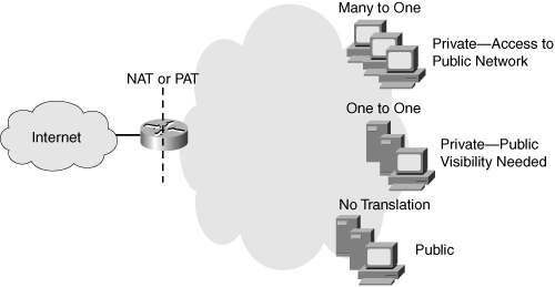
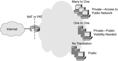
![]() Dynamic NAT maps an unregistered IP address to a registered IP address from a group of registered IP addresses. NAT overloading, or PAT, is a form of dynamic NAT that maps multiple unregistered IP addresses to a single registered IP address by using different port numbers. As shown in Figure 6-2, NAT or PAT can be used to translate the following:
Dynamic NAT maps an unregistered IP address to a registered IP address from a group of registered IP addresses. NAT overloading, or PAT, is a form of dynamic NAT that maps multiple unregistered IP addresses to a single registered IP address by using different port numbers. As shown in Figure 6-2, NAT or PAT can be used to translate the following:
-
 One private address to one public address: Used in cases when servers on the internal network with private IP addresses must be visible from the public network. The translation from the server’s private IP address to the public IP address is defined statically.
 -
 Many private addresses to one public address: Used for end systems that require access to the public network but do not have to be visible to the outside world.
 -
 Combination: It is common to see a combination of the previous two techniques deployed throughout networks.
![]() For additional details about NAT and PAT, see Appendix D, “Network Address Translation.”
For additional details about NAT and PAT, see Appendix D, “Network Address Translation.”
Guidelines for the Use of Private and Public Addresses in an Enterprise Network
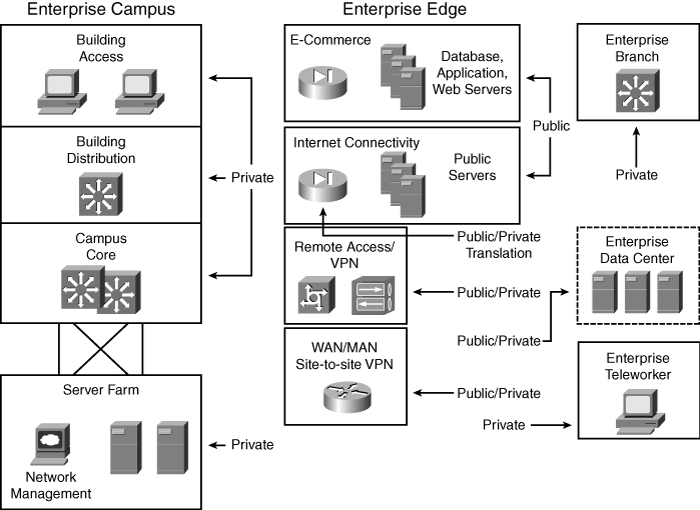
![]() As shown in Figure 6-3, the typical enterprise network uses both private and public IP addresses.
As shown in Figure 6-3, the typical enterprise network uses both private and public IP addresses.
![]() Private IP addresses are used throughout the Enterprise Campus, Enterprise Branch, and Enterprise Teleworker modules. The following modules include public addresses:
Private IP addresses are used throughout the Enterprise Campus, Enterprise Branch, and Enterprise Teleworker modules. The following modules include public addresses:
-
 The Internet Connectivity module, where public IP addresses are used for Internet connections and publicly accessible servers.
 -
 The E-commerce module, where public IP addresses are used for the database, application, and web servers.
 -
 The Remote Access and virtual private network (VPN) module, the Enterprise Data Center module, and the WAN and metropolitan-area network (MAN) and Site-to-Site VPN module, where public IP addresses are used for certain connections.
 Determining the Size of the Network
![]() The first step in designing an IP addressing plan is determining the size of the network to establish how many IP subnets and how many IP addresses are needed on each subnet. To gather this information, answer the following questions:
The first step in designing an IP addressing plan is determining the size of the network to establish how many IP subnets and how many IP addresses are needed on each subnet. To gather this information, answer the following questions:
-
 How many locations does the network consist of?: The designer must determine the number and type of locations.
 -
 How many devices in each location need addresses?: The network designer must determine the number of devices that need to be addressed, including end systems, router interfaces, switches, firewall interfaces, and any other devices.
 -
 What are the IP addressing requirements for individual locations?: The designer must collect information about which systems will use dynamic addressing, which will use static addresses, and which systems can use private instead of public addresses.
 -
 What subnet size is appropriate?: Based on the collected information about the number of networks and planned switch deployment, the designer estimates the appropriate subnet size. For example, deploying 48-port switches would mean that subnets with 64 host addresses would be appropriate, assuming one device per port.
Determining the Network Topology
![]() Initially, the designer should acquire a general picture of the network topology; this will help determine the correct information to gather about network size and its relation to the IP addressing plan.
Initially, the designer should acquire a general picture of the network topology; this will help determine the correct information to gather about network size and its relation to the IP addressing plan.
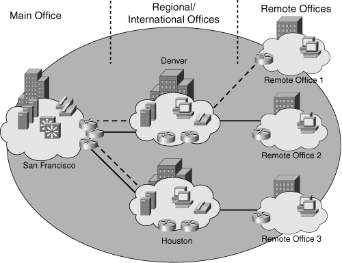
![]() With this general network topology information, the designer determines the number of locations, location types, and their correlations. For example, the network location information for the topology shown in Figure 6-4 is shown in Table 6-1.
With this general network topology information, the designer determines the number of locations, location types, and their correlations. For example, the network location information for the topology shown in Figure 6-4 is shown in Table 6-1.
|
|
|
|
|---|---|---|
|
|
|
|
|
|
|
|
|
|
|
|
|
|
| |
|
|
|
|
|
|
|
|
Size of Individual Locations
![]() The network size, in terms of the IP addressing plan, relates to the number of devices and interfaces that need an IP address. To establish the overall network size in a simplistic way, the designer determines the approximate number of workstations, servers, Cisco IP phones, router interfaces, switch management and Layer 3 interfaces, firewall interfaces, and other network devices at each location. This estimate provides the minimum overall number of IP addresses that are needed for the network. Table 6-2 provides the IP address requirements by location for the topology shown in Figure 6-4.
The network size, in terms of the IP addressing plan, relates to the number of devices and interfaces that need an IP address. To establish the overall network size in a simplistic way, the designer determines the approximate number of workstations, servers, Cisco IP phones, router interfaces, switch management and Layer 3 interfaces, firewall interfaces, and other network devices at each location. This estimate provides the minimum overall number of IP addresses that are needed for the network. Table 6-2 provides the IP address requirements by location for the topology shown in Figure 6-4.
|
|
|
|
|
|
|
|
|
|
|
|---|---|---|---|---|---|---|---|---|---|
|
|
|
|
|
|
|
|
|
|
|
|
|
|
|
|
|
|
|
|
|
|
|
|
|
|
|
|
|
|
|
|
|
|
|
|
|
|
|
|
|
|
|
|
|
|
|
|
|
|
|
|
|
|
|
|
|
|
|
|
|
|
|
|
|
|
|
|
|
|
|
|
|
|
|
![]() Some additional addresses should be reserved to allow for seamless potential network growth. The commonly suggested reserve is 20 percent for main and regional offices, and 10 percent for remote offices; however, this can vary from case to case. The designer should carefully discuss future network growth with the organization’s representative to obtain a more precise estimate of the required resources.
Some additional addresses should be reserved to allow for seamless potential network growth. The commonly suggested reserve is 20 percent for main and regional offices, and 10 percent for remote offices; however, this can vary from case to case. The designer should carefully discuss future network growth with the organization’s representative to obtain a more precise estimate of the required resources.
 Planning the IP Addressing Hierarchy
![]() The IP addressing hierarchy influences network routing. This section describes IP addressing hierarchy and how it reduces routing overhead. This section discusses the issues that influence the IP addressing plan and the routing protocol choice, including summarization, fixed-length subnet masking, variable-length subnet masking, and classful and classless routing protocols.
The IP addressing hierarchy influences network routing. This section describes IP addressing hierarchy and how it reduces routing overhead. This section discusses the issues that influence the IP addressing plan and the routing protocol choice, including summarization, fixed-length subnet masking, variable-length subnet masking, and classful and classless routing protocols.
| Note |
|
Hierarchical Addressing
![]() The telephone numbering system is a hierarchical system. For example, the North American Numbering Plan includes the country code, the area code, the local exchange, and the line number.
The telephone numbering system is a hierarchical system. For example, the North American Numbering Plan includes the country code, the area code, the local exchange, and the line number.
![]() The telephone architecture has handled prefix routing, or routing based only on the prefix part of the address, for many years. For example, a telephone switch in Detroit, Michigan does not have to know how to reach a specific line in Portland, Oregon. It must simply recognize that the call is not local. A long-distance carrier must recognize that area code 503 is for Oregon, but it does not have to know the details of how to reach the specific line in Oregon.
The telephone architecture has handled prefix routing, or routing based only on the prefix part of the address, for many years. For example, a telephone switch in Detroit, Michigan does not have to know how to reach a specific line in Portland, Oregon. It must simply recognize that the call is not local. A long-distance carrier must recognize that area code 503 is for Oregon, but it does not have to know the details of how to reach the specific line in Oregon.
![]() The IP addressing scheme is also hierarchical, and prefix routing is not new in the IP environment either. As in the telephone example, IP routers make hierarchical decisions. Recall that an IP address comprises a prefix part and a host part. A router has to know only how to reach the next hop; it does not have to know the details of how to reach an end node that is not local. Routers use the prefix to determine the path for a destination address that is not local. The host part is used to reach local hosts.
The IP addressing scheme is also hierarchical, and prefix routing is not new in the IP environment either. As in the telephone example, IP routers make hierarchical decisions. Recall that an IP address comprises a prefix part and a host part. A router has to know only how to reach the next hop; it does not have to know the details of how to reach an end node that is not local. Routers use the prefix to determine the path for a destination address that is not local. The host part is used to reach local hosts.
Route Summarization
![]() With route summarization, also referred to as route aggregation or supernetting, one route in the routing table represents many other routes. Summarizing routes reduces the routing update traffic (which can be important on low-speed links) and reduces the number of routes in the routing table and overall router overhead in the router receiving the routes. In a hierarchical network design, effective use of route summarization can limit the impact of topology changes to the routers in one section of the network.
With route summarization, also referred to as route aggregation or supernetting, one route in the routing table represents many other routes. Summarizing routes reduces the routing update traffic (which can be important on low-speed links) and reduces the number of routes in the routing table and overall router overhead in the router receiving the routes. In a hierarchical network design, effective use of route summarization can limit the impact of topology changes to the routers in one section of the network.
![]() If the Internet had not adapted route summarization by standardizing on classless interdomain routing (CIDR), it would not have survived.
If the Internet had not adapted route summarization by standardizing on classless interdomain routing (CIDR), it would not have survived.
![]() For summarization to work correctly, the following requirements must be met:
For summarization to work correctly, the following requirements must be met:
-
 Multiple IP addresses must share the same leftmost bits.
 -
 Routers must base their routing decisions on a 32-bit IP address and a prefix length of up to 32 bits.
 -
 Routing protocols must carry the prefix length with the 32-bit IP address.
![]() For example, assume that a router has the following networks behind it:
For example, assume that a router has the following networks behind it:
-
 192.168.168.0/24
 -
 192.168.169.0/24
 -
 192.168.170.0/24
 -
 192.168.171.0/24
 -
 192.168.172.0/24
 -
 192.168.173.0/24
 -
 192.168.174.0/24
 -
 192.168.175.0/24
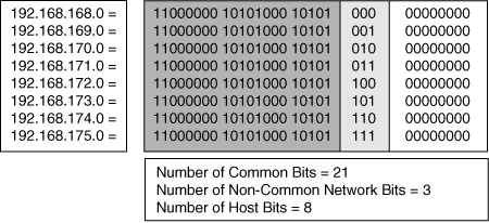
![]() Each of these networks could be advertised separately; however, this would mean advertising eight routes. Instead, this router can summarize the eight routes into one route and advertise 192.168.168.0/21. By advertising this one route, the router is saying, “Route packets to me if the destination has the first 21 bits the same as the first 21 bits of 192.168.168.0.”
Each of these networks could be advertised separately; however, this would mean advertising eight routes. Instead, this router can summarize the eight routes into one route and advertise 192.168.168.0/21. By advertising this one route, the router is saying, “Route packets to me if the destination has the first 21 bits the same as the first 21 bits of 192.168.168.0.”
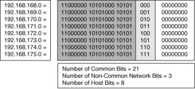
![]() Figure 6-5 illustrates how this summary route is determined. The addresses all have the first 21 bits in common and include all the combinations of the other 3 bits in the network portion of the address; therefore, only the first 21 bits are needed to determine whether the router can route to one of these specific addresses.
Figure 6-5 illustrates how this summary route is determined. The addresses all have the first 21 bits in common and include all the combinations of the other 3 bits in the network portion of the address; therefore, only the first 21 bits are needed to determine whether the router can route to one of these specific addresses.
IP Addressing Hierarchy Criteria
![]() IP addressing hierarchy has an important impact on the routing protocol choice, and vice versa. The decision about how to implement the IP addressing hierarchy is usually based on the following questions:
IP addressing hierarchy has an important impact on the routing protocol choice, and vice versa. The decision about how to implement the IP addressing hierarchy is usually based on the following questions:
-
 Is hierarchy needed within the IP addressing plan?
 -
 What are the criteria for dividing the network into route summarization groups?
 -
 How is route summarization performed, and what is the correlation with routing?
 -
 Is a hierarchy of route summarization groups required?
 -
 How many end systems does each route summarization group or subgroup contain?
Benefits of Hierarchical Addressing
![]() A network designer decides how to implement the IP addressing hierarchy based on the network’s size, geography, and topology. In large networks, hierarchy within the IP addressing plan is mandatory for a stable network (including stable routing tables). For the following reasons, a planned, hierarchical IP addressing structure, with room for growth, is recommended for networks of all sizes:
A network designer decides how to implement the IP addressing hierarchy based on the network’s size, geography, and topology. In large networks, hierarchy within the IP addressing plan is mandatory for a stable network (including stable routing tables). For the following reasons, a planned, hierarchical IP addressing structure, with room for growth, is recommended for networks of all sizes:
-
 Influence of IP addressing on routing: An IP addressing plan influences the network’s overall routing. Before allocating blocks of IP addresses to various parts of the network and assigning IP addresses to devices, consider the criteria for an appropriate and effective IP addressing scheme. Routing stability, service availability, network scalability, and modularity are some crucial and preferred network characteristics and are directly affected by IP address allocation and deployment.
 -
 Modular design and scalable solutions: Whether building a new network or adding a new service on top of an existing infrastructure, a modular design helps to deliver a long-term, scalable solution. IP addressing modularity allows the aggregation of routing information on a hierarchical basis.
 -
 Route aggregation: Route aggregation is used to reduce routing overhead and improve routing stability and scalability. However, to implement route aggregation, a designer must be able to divide a network into contiguous IP address areas and must have a solid understanding of IP address assignment, route aggregation, and hierarchical routing.
Summarization Groups
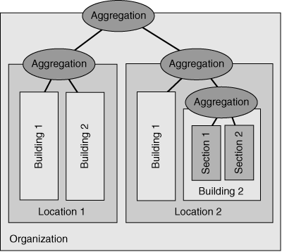
![]() To reduce the routing overhead in a large network, a multilevel hierarchy might be required. The depth of hierarchy depends on the network size and the size of the highest-level summarization group. Figure 6-6 shows an example of a network hierarchy.
To reduce the routing overhead in a large network, a multilevel hierarchy might be required. The depth of hierarchy depends on the network size and the size of the highest-level summarization group. Figure 6-6 shows an example of a network hierarchy.
![]() A typical organization has up to three levels of hierarchy:
A typical organization has up to three levels of hierarchy:
-
 First level: Network locations typically represent the first level of hierarchy in enterprise networks. Each location typically represents a group of summarized subnets, known as a summarization group.
 -
 Second level: A second level of hierarchy can be done within first-level summarization groups. For example, a large location can be divided into smaller summarization groups that represent the buildings or cities within that location. Not all first-level summarization groups require a second level of hierarchy.
 -
 Third level: To further minimize the potential routing overhead and instability, a third level of hierarchy can exist within the second-level summarization group. For example, sections or floors within individual buildings can represent the third-level summarization group.
Impact of Poorly Designed IP Addressing
![]() A poorly designed IP addressing scheme usually results in IP addresses that are randomly assigned on an as-needed basis. In this case, the IP addresses are most likely dispersed through the network with no thought as to whether they can be grouped or summarized. A poor design provides no opportunity for dividing the network into contiguous address areas, and therefore no means of implementing route summarization.
A poorly designed IP addressing scheme usually results in IP addresses that are randomly assigned on an as-needed basis. In this case, the IP addresses are most likely dispersed through the network with no thought as to whether they can be grouped or summarized. A poor design provides no opportunity for dividing the network into contiguous address areas, and therefore no means of implementing route summarization.
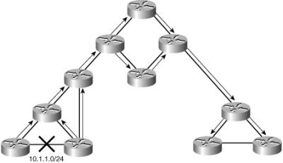
![]() Figure 6-7 is a sample network with poorly designed IP addressing; it uses a dynamic routing protocol. Suppose that a link in the network is flapping (changing its state from UP to DOWN, and vice versa) ten times per minute. Because dynamic routing is used, the routers that detect the change send routing updates to their neighbors, those neighbors send it to their neighbors, and so on. Because aggregation is not possible, the routing update is propagated throughout the entire network, even if there is no need for a distant router to have detailed knowledge of that link.
Figure 6-7 is a sample network with poorly designed IP addressing; it uses a dynamic routing protocol. Suppose that a link in the network is flapping (changing its state from UP to DOWN, and vice versa) ten times per minute. Because dynamic routing is used, the routers that detect the change send routing updates to their neighbors, those neighbors send it to their neighbors, and so on. Because aggregation is not possible, the routing update is propagated throughout the entire network, even if there is no need for a distant router to have detailed knowledge of that link.
![]() Impacts of poorly designed IP addressing include the following:
Impacts of poorly designed IP addressing include the following:
-
 Excess routing traffic consumes bandwidth: When any route changes, routers send routing updates. Without summarization, more updates are sent, and the routing traffic consumes more bandwidth.
 -
 Increased routing table recalculation: Routing updates require routing table recalculation, which affects the router’s performance and ability to forward traffic.
 -
 Possibility of routing loops: When too many routing changes prevent routers from converging with their neighbors, routing loops might occur, which might have global consequences for an organization.
Benefits of Route Aggregation
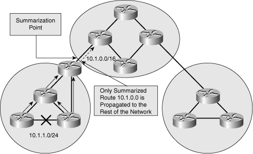
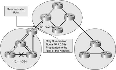
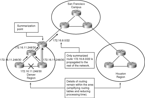
![]() Implementing route aggregation on border routers between contiguously addressed areas controls routing table size. Figure 6-8 shows an example of implementing route summarization (aggregation) on the area borders in a sample network. If a link within an area fails, routing updates are not propagated to the rest of the network, because only the summarized route is sent to the rest of the network, and it has not changed; the route information about the failed link stays within the area. This reduces bandwidth consumption related to routing overhead and relieves routers from unnecessary routing table recalculation.
Implementing route aggregation on border routers between contiguously addressed areas controls routing table size. Figure 6-8 shows an example of implementing route summarization (aggregation) on the area borders in a sample network. If a link within an area fails, routing updates are not propagated to the rest of the network, because only the summarized route is sent to the rest of the network, and it has not changed; the route information about the failed link stays within the area. This reduces bandwidth consumption related to routing overhead and relieves routers from unnecessary routing table recalculation.
![]() Efficient aggregation of routing advertisements narrows the scope of routing update propagation and significantly decreases the cumulative frequency of routing updates.
Efficient aggregation of routing advertisements narrows the scope of routing update propagation and significantly decreases the cumulative frequency of routing updates.
Fixed- and Variable-Length Subnet Masks
![]() Another consideration when designing the IP addressing hierarchy is the subnet mask to use—either the same mask for the entire major network or different masks for different parts of the major network.
Another consideration when designing the IP addressing hierarchy is the subnet mask to use—either the same mask for the entire major network or different masks for different parts of the major network.
![]() Some routing protocols require FLSM; others allow VLSM.
Some routing protocols require FLSM; others allow VLSM.
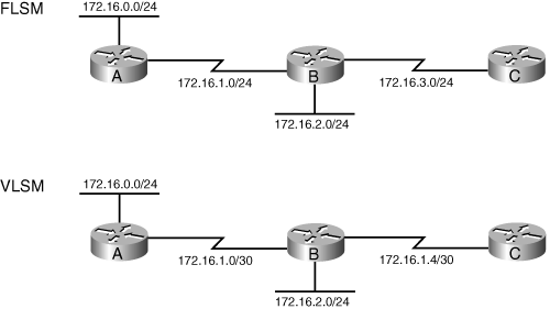
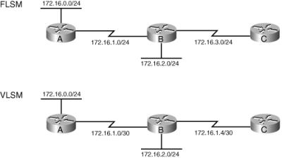
![]() FLSM requires that all subnets of a major network have the same subnet mask, which therefore results in less efficient address space allocation. For example, in the top network shown in Figure 6-9, network 172.16.0.0/16 is subnetted using FLSM. Each subnet is given a /24 mask. The network is composed of multiple LANs that are connected by point-to-point WAN links. Because FLSM is used, all subnets have the same subnet mask. This is inefficient, because even though only two addresses are needed on the point-to-point links, a /24 subnet mask with 254 available host addresses is used.
FLSM requires that all subnets of a major network have the same subnet mask, which therefore results in less efficient address space allocation. For example, in the top network shown in Figure 6-9, network 172.16.0.0/16 is subnetted using FLSM. Each subnet is given a /24 mask. The network is composed of multiple LANs that are connected by point-to-point WAN links. Because FLSM is used, all subnets have the same subnet mask. This is inefficient, because even though only two addresses are needed on the point-to-point links, a /24 subnet mask with 254 available host addresses is used.
![]() VLSM makes it possible to subnet with different subnet masks and therefore results in more efficient address space allocation. VLSM also provides a greater capability to perform route summarization, because it allows more hierarchical levels within an addressing plan. VLSM requires prefix length information to be explicitly sent with each address advertised in a routing update.
VLSM makes it possible to subnet with different subnet masks and therefore results in more efficient address space allocation. VLSM also provides a greater capability to perform route summarization, because it allows more hierarchical levels within an addressing plan. VLSM requires prefix length information to be explicitly sent with each address advertised in a routing update.
![]() For example, in the lower network shown in Figure 6-9, network 172.16.0.0/16 is subnetted using VLSM. The network is composed of multiple LANs that are connected by point-to-point WAN links. The point-to-point links have a subnet mask of /30, providing only two available host addresses, which is all that is needed on these links. The LANs have a subnet mask of /24 because they have more hosts that require addresses.
For example, in the lower network shown in Figure 6-9, network 172.16.0.0/16 is subnetted using VLSM. The network is composed of multiple LANs that are connected by point-to-point WAN links. The point-to-point links have a subnet mask of /30, providing only two available host addresses, which is all that is needed on these links. The LANs have a subnet mask of /24 because they have more hosts that require addresses.
Routing Protocol Considerations
![]() To use VLSM, the routing protocol in use must be classless. Classful routing protocols permit only FLSM.
To use VLSM, the routing protocol in use must be classless. Classful routing protocols permit only FLSM.
Classful Routing Protocols
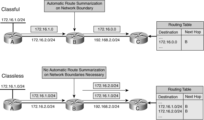
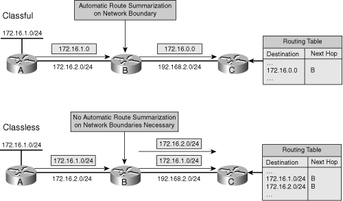
![]() As illustrated at the top of Figure 6-10, the following rules apply when classful routing protocols are used:
As illustrated at the top of Figure 6-10, the following rules apply when classful routing protocols are used:
-
 The routing updates do not include subnet masks.
 -
 When a routing update is received and the routing information is about one of the following:
-
 Routes within the same major network as configured on the receiving interface, the subnet mask configured on the receiving interface is assumed to apply to the received routes also. Therefore, the mask must be the same for all subnets of a major network. In other words, subnetting must be done with FLSM.
 -
 Routes in a different major network than configured on the receiving interface, the default major network mask is assumed to apply to the received routes. Therefore, automatic route summarization is performed across major network (Class A, B, or C) boundaries, and subnetted networks must be contiguous.
-
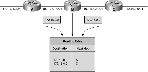
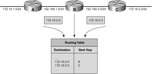
![]() Figure 6-11 illustrates a sample network with a discontiguous 172.16.0.0 network that runs a classful routing protocol. Routers A and C automatically summarize across the major network boundary, so both send routing information about 172.16.0.0 rather than the individual subnets (172.16.1.0/24 and 172.16.2.0/24). Consequently, Router B receives two entries for the major network 172.16.0.0, and it puts both entries into its routing table. Router B therefore might make incorrect routing decisions.
Figure 6-11 illustrates a sample network with a discontiguous 172.16.0.0 network that runs a classful routing protocol. Routers A and C automatically summarize across the major network boundary, so both send routing information about 172.16.0.0 rather than the individual subnets (172.16.1.0/24 and 172.16.2.0/24). Consequently, Router B receives two entries for the major network 172.16.0.0, and it puts both entries into its routing table. Router B therefore might make incorrect routing decisions.
![]() Because of these constraints, classful routing is not often used in modern networks. Routing Information Protocol (RIP) version 1 (RIPv1) is an example of a classful routing protocol.
Because of these constraints, classful routing is not often used in modern networks. Routing Information Protocol (RIP) version 1 (RIPv1) is an example of a classful routing protocol.
Classless Routing Protocols
![]() As illustrated in the lower portion of Figure 6-10, the following rules apply when classless routing protocols are used:
As illustrated in the lower portion of Figure 6-10, the following rules apply when classless routing protocols are used:
-
 The routing updates include subnet masks.
 -
 VLSM is supported.
 -
 Automatic route summarization at the major network boundary is not required, and route summarization can be manually configured.
 -
 Subnetted networks can be discontiguous.
![]() Consequently, all modern networks should use classless routing. Examples of classless routing protocols include RIP version 2 (RIPv2), Enhanced Interior Gateway Routing Protocol (EIGRP), OSPF, IS-IS, and Border Gateway Protocol (BGP).
Consequently, all modern networks should use classless routing. Examples of classless routing protocols include RIP version 2 (RIPv2), Enhanced Interior Gateway Routing Protocol (EIGRP), OSPF, IS-IS, and Border Gateway Protocol (BGP).
| Note |
|
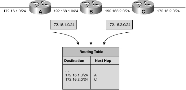
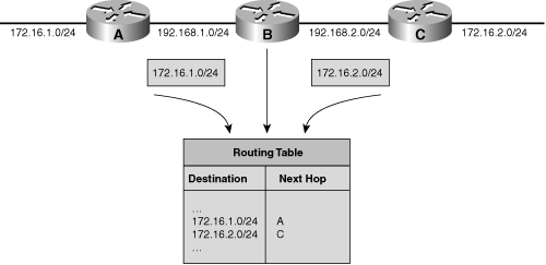
![]() Figure 6-12 illustrates how discontiguous networks are handled by a classless routing protocol. This figure shows the same network as in Figure 6-11, but running a classless routing protocol that does not automatically summarize at the network boundary. In this example, Router B learns about both subnetworks 172.16.1.0/24 and 172.16.2.0/24, one from each interface; routing is performed correctly.
Figure 6-12 illustrates how discontiguous networks are handled by a classless routing protocol. This figure shows the same network as in Figure 6-11, but running a classless routing protocol that does not automatically summarize at the network boundary. In this example, Router B learns about both subnetworks 172.16.1.0/24 and 172.16.2.0/24, one from each interface; routing is performed correctly.
| Note |
|
Hierarchical IP Addressing and Summarization Plan Example
![]() Recall that the number of available host addresses on a subnet is calculated by the formula 2h – 2, where h is the number of host bits (the number of bits set to 0 in the subnet mask).
Recall that the number of available host addresses on a subnet is calculated by the formula 2h – 2, where h is the number of host bits (the number of bits set to 0 in the subnet mask).
![]() The first two columns in Table 6-3 show the location and number of IP addresses required at each location for the sample network shown in Figure 6-4. The third column in this table is the next highest power of 2 from the required number of addresses; this value is used to calculate the required number of host bits, as shown in the fourth column. Assuming that the Class B address 172.16.0.0/16 is used to address this network, the fifth column illustrates sample address blocks allocated to each location.
The first two columns in Table 6-3 show the location and number of IP addresses required at each location for the sample network shown in Figure 6-4. The third column in this table is the next highest power of 2 from the required number of addresses; this value is used to calculate the required number of host bits, as shown in the fourth column. Assuming that the Class B address 172.16.0.0/16 is used to address this network, the fifth column illustrates sample address blocks allocated to each location.
|
|
|
|
|
|
|---|---|---|---|---|
|
|
|
|
|
|
|
|
|
|
| |
|
|
|
|
|
|
|
|
|
|
|
|
|
|
|
|
|
|
|
| |
|
|
|
|
|
|
|
|
|
|
![]() For the main campus, 2048 addresses are allocated; 11 host bits are required. This subnet is further divided into smaller subnets supporting floors or wiring closets. For the Denver region, 1024 addresses are allocated; 10 host bits are required. This address block is further divided into smaller subnets supporting buildings, floors, or wiring closets. Similarly, for the Houston region, 1024 addresses are also allocated and further subdivided, as shown in Table 6-3.
For the main campus, 2048 addresses are allocated; 11 host bits are required. This subnet is further divided into smaller subnets supporting floors or wiring closets. For the Denver region, 1024 addresses are allocated; 10 host bits are required. This address block is further divided into smaller subnets supporting buildings, floors, or wiring closets. Similarly, for the Houston region, 1024 addresses are also allocated and further subdivided, as shown in Table 6-3.
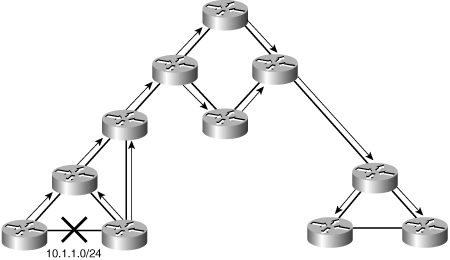
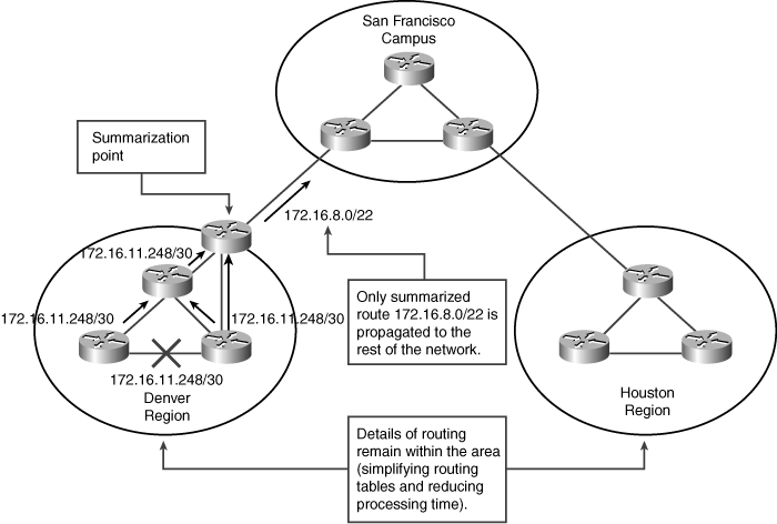
![]() Figure 6-13 illustrates one of the links in the Denver region going down and how summarization is performed to reduce routing update traffic.
Figure 6-13 illustrates one of the links in the Denver region going down and how summarization is performed to reduce routing update traffic.
 Methods of Assigning IP Addresses
![]() This section discusses methods of assigning IP addresses to end systems and explains their influence on administrative overhead. Address assignment includes assigning an IP address, a default gateway, one or more domain name servers that resolve names to IP addresses, time servers, and so forth. Before selecting the desired IP address assignment method, the following questions should be answered:
This section discusses methods of assigning IP addresses to end systems and explains their influence on administrative overhead. Address assignment includes assigning an IP address, a default gateway, one or more domain name servers that resolve names to IP addresses, time servers, and so forth. Before selecting the desired IP address assignment method, the following questions should be answered:
-
 How many devices need an IP address?
 -
 Which devices require static IP address assignment?
 -
 Is the administrator required to track devices and their IP addresses?
 -
 Do additional parameters (default gateway, name server, and so forth) have to be configured?
 -
 Are there any availability issues?
 -
 Are there any security issues?
Static Versus Dynamic IP Address Assignment Methods
![]() Following are the two basic IP address assignment strategies:
Following are the two basic IP address assignment strategies:
-
 Static: An IP address is statically assigned to a system. The network administrator configures the IP address, default gateway, and name servers manually by entering them into a special file or files on the end system with either a graphical or text interface. Static address assignment is an extra burden for the administrator—especially on large-scale networks—who must configure the address on every end system in the network.
 -
 Dynamic: IP addresses are dynamically assigned to the end systems. Dynamic address assignment relieves the administrator of manually assigning an address to every network device. Instead, the administrator must set up a server to assign the addresses. On that server, the administrator defines the address pools and additional parameters that should be sent to the host (default gateway, name servers, time servers, and so forth). On the host, the administrator enables the host to acquire the address dynamically; this is often the default. When IP address reconfiguration is needed, the administrator reconfigures the server, which then performs the host-renumbering task. Examples of available address assignment protocols include Reverse Address Resolution Protocol, Boot Protocol, and DHCP. DHCP is the newest and provides the most features.
When to Use Static or Dynamic Address Assignment
![]() To select either a static or dynamic end system IP address assignment method or a combination of the two, consider the following:
To select either a static or dynamic end system IP address assignment method or a combination of the two, consider the following:
-
 Node type: Network devices such as routers and switches typically have static addresses.
 End-user devices such as PCs typically have dynamic addresses.
 -
 The number of end systems: If there are more than 30 end systems, dynamic address assignment is preferred. Static assignment can be used for smaller networks.
 -
 Renumbering: If renumbering is likely to happen and there are many end systems, dynamic address assignment is the best choice. With DHCP, only DHCP server reconfiguration is needed; with static assignment, all hosts must be reconfigured.
 -
 Address tracking: If the network policy requires address tracking, the static address assignment method might be easier to implement than the dynamic address assignment method. However, address tracking is also possible with dynamic address assignment with additional DHCP server configuration.
 -
 Additional parameters: DHCP is the easiest solution when additional parameters must be configured. The parameters have to be entered only on the DHCP server, which then sends the address and those parameters to the clients.
 -
 High availability: Statically assigned IP addresses are always available. Dynamically assigned IP addresses must be acquired from the server; if the server fails, the addresses cannot be acquired. To ensure reliability, a redundant DHCP server is required.
 -
 Security: With dynamic IP address assignment, anyone who connects to the network can acquire a valid IP address, in most cases. This might be a security risk. Static IP address assignment poses only a minor security risk.
![]() The use of one address assignment method does not exclude the use of another in a different part of the network.
The use of one address assignment method does not exclude the use of another in a different part of the network.
Guidelines for Assigning IP Addresses in the Enterprise Network
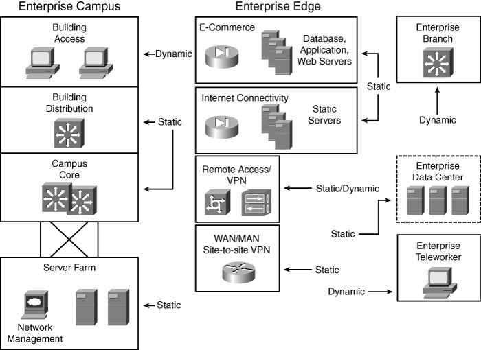
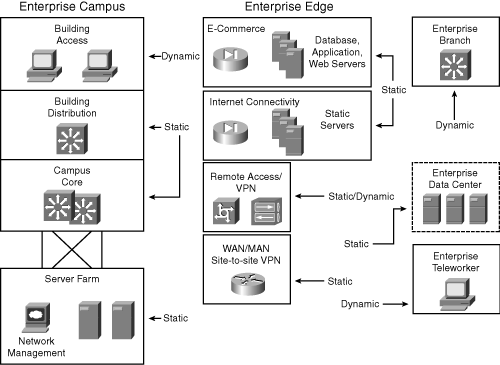
![]() The typical enterprise network uses both static and dynamic address assignment methods. As shown in Figure 6-14, the static IP address assignment method is typically used for campus network infrastructure devices, in the Server Farm and Enterprise Data Center modules, and in the modules of the Enterprise Edge (the E-Commerce, Internet Connectivity, Remote Access and VPN, and WAN and MAN and Site-to-Site VPN modules). Static addresses are required for systems such as servers or network devices, in which the IP address must be known at all times for connectivity, general access, or management.
The typical enterprise network uses both static and dynamic address assignment methods. As shown in Figure 6-14, the static IP address assignment method is typically used for campus network infrastructure devices, in the Server Farm and Enterprise Data Center modules, and in the modules of the Enterprise Edge (the E-Commerce, Internet Connectivity, Remote Access and VPN, and WAN and MAN and Site-to-Site VPN modules). Static addresses are required for systems such as servers or network devices, in which the IP address must be known at all times for connectivity, general access, or management.
![]() Dynamic IP address assignment is used for assigning IP addresses to end-user devices, including workstations, Cisco IP phones, and mobile devices.
Dynamic IP address assignment is used for assigning IP addresses to end-user devices, including workstations, Cisco IP phones, and mobile devices.
Using DHCP to Assign IP Addresses
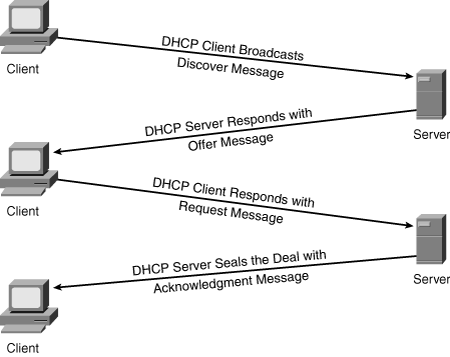
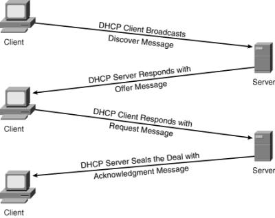
![]() DHCP is used to provide dynamic IP address allocation to hosts. DHCP uses a client/server model; the DHCP server can be a Windows server, a UNIX-based server, or a Cisco IOS device. Cisco IOS devices can also be DHCP relay agents and DHCP clients. Figure 6-15 shows the steps that occur when a DHCP client requests an IP address from a DHCP server.
DHCP is used to provide dynamic IP address allocation to hosts. DHCP uses a client/server model; the DHCP server can be a Windows server, a UNIX-based server, or a Cisco IOS device. Cisco IOS devices can also be DHCP relay agents and DHCP clients. Figure 6-15 shows the steps that occur when a DHCP client requests an IP address from a DHCP server.
![]() A DHCP client might receive offers from multiple DHCP servers and can accept any one of the offers; the client usually accepts the first offer it receives. An offer from the DHCP server is not a guarantee that the IP address will be allocated to the client; however, the server usually reserves the address until the client has had a chance to formally accept the address.
A DHCP client might receive offers from multiple DHCP servers and can accept any one of the offers; the client usually accepts the first offer it receives. An offer from the DHCP server is not a guarantee that the IP address will be allocated to the client; however, the server usually reserves the address until the client has had a chance to formally accept the address.
![]() DHCP supports three possible address allocation mechanisms:
DHCP supports three possible address allocation mechanisms:
-
 Manual: The network administrator assigns an IP address to a specific MAC address. DHCP is used to dispatch the assigned address to the host.
 -
 Automatic: DHCP permanently assigns the IP address to a host.
 -
 Dynamic: DHCP assigns the IP address to a host for a limited time (called a lease) or until the host explicitly releases the address. This mechanism supports automatic address reuse when the host to which the address has been assigned no longer needs the address.
 Name Resolution
![]() Names are used to identify different hosts and resources on the network and to provide user-friendly interaction with computers; a name is much easier to remember than an IP address. This section covers the purpose of name resolution, provides information about different available name resolution strategies, and discusses Domain Name System (DNS) name resolution.
Names are used to identify different hosts and resources on the network and to provide user-friendly interaction with computers; a name is much easier to remember than an IP address. This section covers the purpose of name resolution, provides information about different available name resolution strategies, and discusses Domain Name System (DNS) name resolution.
![]() Hosts (computers, servers, printers, and so forth) identify themselves to each other using various naming schemes. Each computer on the network can have an assigned name to provide easier communication between devices and among users. Because the IP network layer protocol uses IP addresses to transport datagrams, a name that is used to identify a host must be mapped or resolved into an IP address; this is known as name resolution. To select the desired name resolution method, the following questions should be answered:
Hosts (computers, servers, printers, and so forth) identify themselves to each other using various naming schemes. Each computer on the network can have an assigned name to provide easier communication between devices and among users. Because the IP network layer protocol uses IP addresses to transport datagrams, a name that is used to identify a host must be mapped or resolved into an IP address; this is known as name resolution. To select the desired name resolution method, the following questions should be answered:
-
 How many hosts require name resolution?
 -
 Are applications that depend on name resolution present?
 -
 Is the network isolated, or is it connected to the Internet?
 -
 If the network is isolated, how frequently are new hosts added, and how frequently do names change?
Static Versus Dynamic Name Resolution
![]() The process of resolving a hostname to an IP address can be either static or dynamic. Following are the differences between these two methods:
The process of resolving a hostname to an IP address can be either static or dynamic. Following are the differences between these two methods:
-
 Static: With static name-to-IP-address resolution, both the administrative overhead and the configuration are very similar to those of a static address assignment strategy. The network administrator manually defines name-to-IP-address resolutions by entering the name and IP address pairs into the local database (HOSTS file) using either a graphical or text interface. Manual entries create additional work for the administrator; they must be entered on every host and are prone to errors and omissions.
 -
 Dynamic: The dynamic name-to-IP-address resolution is similar to the dynamic address assignment strategy. The administrator has to enter the name-to-IP-address resolutions only on a local DNS server rather than on every host. The DNS server then performs the name-to-IP-address resolution. Renumbering and renaming are easier with the dynamic name-to-IP-address resolution method.
When to Use Static or Dynamic Name Resolution
![]() The selection of either a static or dynamic end-system name resolution method depends on the following criteria:
The selection of either a static or dynamic end-system name resolution method depends on the following criteria:
-
 The number of hosts: If there are more than 30 end systems, dynamic name resolution is preferred. Static name resolution is manageable for fewer hosts.
 -
 Isolated network: If the network is isolated (it does not have any connections to the Internet) and the number of hosts is small, static name resolution might be appropriate. The dynamic method is also possible; the choice is an administrative decision.
 -
 Internet connectivity: When Internet connectivity is available for end users, static name resolution is not an option, and dynamic name resolution using DNS is mandatory.
 -
 Frequent changes and adding of names: When dealing with frequent changes and adding names to a network, dynamic name resolution is recommended.
 -
 Applications depending on name resolution: If applications that depend on name resolution are used, dynamic name resolution is recommended.
Using DNS for Name Resolution
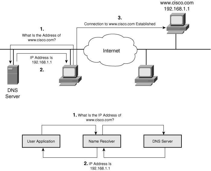
![]() To resolve symbolic names to actual network addresses, applications use resolver or name resolver programs, which are usually part of the host operating system. An application sends a query to a name resolver that resolves the request with either the local database (HOSTS file) or the DNS server.
To resolve symbolic names to actual network addresses, applications use resolver or name resolver programs, which are usually part of the host operating system. An application sends a query to a name resolver that resolves the request with either the local database (HOSTS file) or the DNS server.
![]() When numerous hosts or names must be resolved to IP addresses, statically defined resolutions in HOSTS files are unwieldy to maintain. To ease this process, DNS is used for name resolution. DNS is a client/server mechanism used to access a distributed database providing address-to-name resolution. A DNS server is special software that usually resides on dedicated hardware. DNS servers are organized in a hierarchical structure. A DNS server can query other DNS servers to retrieve partial resolutions for a certain name; for example, one DNS server could resolve cisco.com, and another could resolve www.
When numerous hosts or names must be resolved to IP addresses, statically defined resolutions in HOSTS files are unwieldy to maintain. To ease this process, DNS is used for name resolution. DNS is a client/server mechanism used to access a distributed database providing address-to-name resolution. A DNS server is special software that usually resides on dedicated hardware. DNS servers are organized in a hierarchical structure. A DNS server can query other DNS servers to retrieve partial resolutions for a certain name; for example, one DNS server could resolve cisco.com, and another could resolve www.
![]() To enable DNS name resolution, the network administrator sets up the DNS server, enters information about hostnames and corresponding IP addresses, and configures the hosts to use the DNS server for name resolution.
To enable DNS name resolution, the network administrator sets up the DNS server, enters information about hostnames and corresponding IP addresses, and configures the hosts to use the DNS server for name resolution.
![]() A recommended practice is to use a DNS server for internal name resolution when there are more than 30 hosts, services, or fully qualified domain names (FQDN) to resolve to IP addresses. An external DNS server is required to provide access to hosts outside the organization.
A recommended practice is to use a DNS server for internal name resolution when there are more than 30 hosts, services, or fully qualified domain names (FQDN) to resolve to IP addresses. An external DNS server is required to provide access to hosts outside the organization.
| Note |
|
![]() Figure 6-16 illustrates the process of resolving an IP address using a DNS server:
Figure 6-16 illustrates the process of resolving an IP address using a DNS server:
|
|
|
|
|
|
|
|
|
| Note |
|
| Note |
|
 DHCP and DNS Server Location in a Network
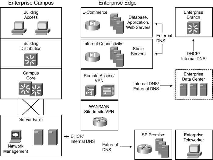
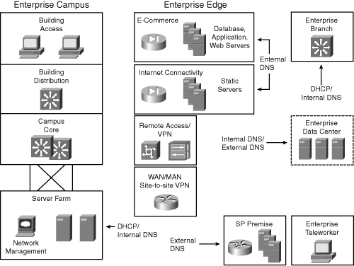
![]() As illustrated in Figure 6-17, DHCP and DNS servers can be located at multiple places in the network, depending on the service they support.
As illustrated in Figure 6-17, DHCP and DNS servers can be located at multiple places in the network, depending on the service they support.
![]() For the Enterprise Campus, DHCP and internal DNS servers should be located in the Server Farm; these servers should be redundant. For remote locations, Cisco routers can provide DHCP and DNS at the Enterprise Edge. External DNS servers should be redundant—for example, at two service provider facilities, or one at a service provider facility and one in a demilitarized zone at the Enterprise Campus or remote data center.
For the Enterprise Campus, DHCP and internal DNS servers should be located in the Server Farm; these servers should be redundant. For remote locations, Cisco routers can provide DHCP and DNS at the Enterprise Edge. External DNS servers should be redundant—for example, at two service provider facilities, or one at a service provider facility and one in a demilitarized zone at the Enterprise Campus or remote data center.

0 comments
Post a Comment