
Area and Domain Summarization
![]() There are many ways to summarize routes in OSPF. The effectiveness of route summarization mechanisms depends on the addressing scheme. Summarization should be supported into and out of areas at the ABR or ASBR. To minimize route information inserted into the area, consider the following guidelines when planning your OSPF internetwork:
There are many ways to summarize routes in OSPF. The effectiveness of route summarization mechanisms depends on the addressing scheme. Summarization should be supported into and out of areas at the ABR or ASBR. To minimize route information inserted into the area, consider the following guidelines when planning your OSPF internetwork:
-
 Configure the network addressing scheme so that the range of subnets assigned within an area is contiguous.
 - Create an address space that will split areas easily as the network grows. If possible, assign subnets according to simple octet boundaries.
- Plan ahead for the addition of new routers to the OSPF environment. Ensure that new routers are inserted appropriately as area, backbone, or border routers.
![]() Figure 3-14 shows some of the ways to summarize routes and otherwise reduce LSA database size and flooding in OSPF:
Figure 3-14 shows some of the ways to summarize routes and otherwise reduce LSA database size and flooding in OSPF:
- Area ranges per the OSPF RFCs
- Area filtering
- Summary address filtering
- Originating default
- Filtering for NSSA routes


OSPF Hub-and-Spoke Design
![]() In an OSPF hub-and-spoke design, any change at one spoke site is passed up the link to the area hub and is then replicated to each of the other spoke sites. These actions can place a great burden on the hub router. Change flooding is the chief problem encountered in these designs.
In an OSPF hub-and-spoke design, any change at one spoke site is passed up the link to the area hub and is then replicated to each of the other spoke sites. These actions can place a great burden on the hub router. Change flooding is the chief problem encountered in these designs.
![]() Stub areas minimize the amount of information within the area. Totally stubby areas are better than stub areas in this regard. If a spoke site must redistribute routes into OSPF, make it a NSSA. Keep in mind that totally stubby NSSAs are also possible.
Stub areas minimize the amount of information within the area. Totally stubby areas are better than stub areas in this regard. If a spoke site must redistribute routes into OSPF, make it a NSSA. Keep in mind that totally stubby NSSAs are also possible.
![]() Limiting the number of spokes per area reduces the flooding at the hub. However, smaller areas allow for less summarization into the backbone. Each spoke requires either a separate interface or a subinterface on the hub router.
Limiting the number of spokes per area reduces the flooding at the hub. However, smaller areas allow for less summarization into the backbone. Each spoke requires either a separate interface or a subinterface on the hub router.
Number of Areas in an OSPF Hub-and-Spoke Design
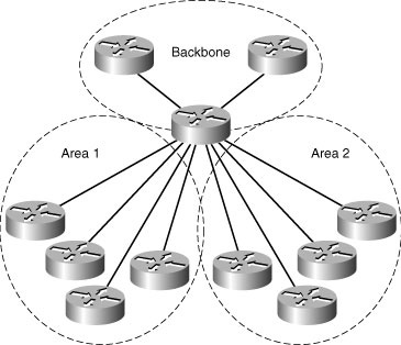
![]() For a hub-and-spoke topology, the number of areas and the number of sites per area will need to be determined (see Figure 3-15).
For a hub-and-spoke topology, the number of areas and the number of sites per area will need to be determined (see Figure 3-15).
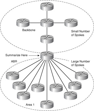
![]() As the number of remote sites goes up, you have to start breaking the network into multiple areas. As already noted, the number of routers per area depends on a couple of factors. If the number of remote sites is low, you can place the hub and its spokes within an area. If there are multiple remote sites, you can make the hub an ABR and split off the spokes in one or more areas.
As the number of remote sites goes up, you have to start breaking the network into multiple areas. As already noted, the number of routers per area depends on a couple of factors. If the number of remote sites is low, you can place the hub and its spokes within an area. If there are multiple remote sites, you can make the hub an ABR and split off the spokes in one or more areas.
![]() In general, the hub should be an ABR, to allow each area to be summarized into the other areas.
In general, the hub should be an ABR, to allow each area to be summarized into the other areas.
![]() The backbone area is extremely important in OSPF. The best approach is to design OSPF to have a small and highly stable area 0. For example, some large Frame Relay or ATM designs have had an area 0 consisting of just the ABRs, all within a couple of racks.
The backbone area is extremely important in OSPF. The best approach is to design OSPF to have a small and highly stable area 0. For example, some large Frame Relay or ATM designs have had an area 0 consisting of just the ABRs, all within a couple of racks.
Issues with Hub-and-Spoke Design
![]() Low-speed links and large numbers of spoke sites are the worst issues for hub-and-spoke design, as illustrated in Figure 3-16.
Low-speed links and large numbers of spoke sites are the worst issues for hub-and-spoke design, as illustrated in Figure 3-16.
![]() Low-speed links and large numbers of spokes may require multiple flooding domains or areas, which you must effectively support. You should balance the number of flooding domains on the hub against the number of spokes in each flooding domain. The link speeds and the amount of information being passed through the network determine the right balance.
Low-speed links and large numbers of spokes may require multiple flooding domains or areas, which you must effectively support. You should balance the number of flooding domains on the hub against the number of spokes in each flooding domain. The link speeds and the amount of information being passed through the network determine the right balance.
![]() Design for these situations must balance:
Design for these situations must balance:
- The number of areas
- The router impact of maintaining an LSA database and doing Dijkstra calculations per area
- The number of remote routers in each area
![]() In situations with low bandwidth, the lack of bandwidth to flood LSAs when changes are occurring or OSPF is initializing becomes a driving factor. The number of routers per area must be strictly limited so that the bandwidth is adequate for LSA flooding under stress conditions (for example, simultaneous router startup or linkup conditions).
In situations with low bandwidth, the lack of bandwidth to flood LSAs when changes are occurring or OSPF is initializing becomes a driving factor. The number of routers per area must be strictly limited so that the bandwidth is adequate for LSA flooding under stress conditions (for example, simultaneous router startup or linkup conditions).
![]() The extreme case of low-bandwidth links might be 9600-b/s links. Areas for a network would consist of, at most, a couple of sites. In this case, another approach to routing might be appropriate. For example, use static routes from the hub out to the spokes, with default routes back to the hub. Flooding reduction, as discussed in the “OSPF Flooding Reduction” section later in this chapter might help, but would not improve bandwidth usage in a worst-case situation. The recommendation for this type of setting is lab testing under worst-case conditions to define the bandwidth requirements.
The extreme case of low-bandwidth links might be 9600-b/s links. Areas for a network would consist of, at most, a couple of sites. In this case, another approach to routing might be appropriate. For example, use static routes from the hub out to the spokes, with default routes back to the hub. Flooding reduction, as discussed in the “OSPF Flooding Reduction” section later in this chapter might help, but would not improve bandwidth usage in a worst-case situation. The recommendation for this type of setting is lab testing under worst-case conditions to define the bandwidth requirements.
OSPF Hub-and-Spoke Network Types
![]() When you use OSPF for hub-and-spoke networks, you have several choices for the type of network you use (see Figure 3-17).
When you use OSPF for hub-and-spoke networks, you have several choices for the type of network you use (see Figure 3-17).


![]() You must use the right combination of network types for OSPF hub and spoke to work well. Generally, it is wisest to use either the point-to-multipoint OSPF network type at the hub site or configure the hub site with point-to-point subinterfaces.
You must use the right combination of network types for OSPF hub and spoke to work well. Generally, it is wisest to use either the point-to-multipoint OSPF network type at the hub site or configure the hub site with point-to-point subinterfaces.
![]() Configuring point to multipoint is simple. The disadvantage of a point-to-multipoint design is that additional host routes are added to the routing table, and the default OPSF hello and dead timer interval is longer. However, point-to-multipoint implementations simplify configuration as compared to broadcast or nonbroadcast multiaccess (NBMA) implementations and conserve IP address space as compared to point-to-point implementations.
Configuring point to multipoint is simple. The disadvantage of a point-to-multipoint design is that additional host routes are added to the routing table, and the default OPSF hello and dead timer interval is longer. However, point-to-multipoint implementations simplify configuration as compared to broadcast or nonbroadcast multiaccess (NBMA) implementations and conserve IP address space as compared to point-to-point implementations.
![]() Configuring point-to-point subinterfaces takes more work initially, perhaps on the order of a few hours. Each subinterface adds a route to the routing table, making this option about equal to point-to-multipoint in terms of routing table impact. More address space gets used up, even with /30 or /31 subnetting for the point-to-point links. On the other hand, after configuration, point-to-point subinterfaces may provide the most stability, with everything including management working well in this environment.
Configuring point-to-point subinterfaces takes more work initially, perhaps on the order of a few hours. Each subinterface adds a route to the routing table, making this option about equal to point-to-multipoint in terms of routing table impact. More address space gets used up, even with /30 or /31 subnetting for the point-to-point links. On the other hand, after configuration, point-to-point subinterfaces may provide the most stability, with everything including management working well in this environment.
![]() The broadcast or NBMA network types are best avoided. Although they can be made to work with some configuration effort, they lead to less stable networks or networks where certain failure modes have odd consequences.
The broadcast or NBMA network types are best avoided. Although they can be made to work with some configuration effort, they lead to less stable networks or networks where certain failure modes have odd consequences.
OSPF Area Border Connection Behavior
![]() OSPF has strict rules for routing. They sometimes cause nonintuitive traffic patterns.
OSPF has strict rules for routing. They sometimes cause nonintuitive traffic patterns.
![]() In Figure 3-18, dual-homed connections in hub-and-spoke networks illustrate a design challenge in OSPF, where connections are parallel to an area border. Traffic crossing the backbone must get into an area by the shortest path, and then stay in that area.
In Figure 3-18, dual-homed connections in hub-and-spoke networks illustrate a design challenge in OSPF, where connections are parallel to an area border. Traffic crossing the backbone must get into an area by the shortest path, and then stay in that area.
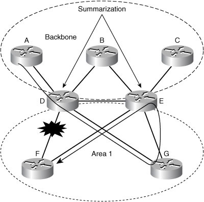
![]() In this example, the link from D to E is in area 0. If the D-to-F link fails, traffic from D to F will go from D to G to E to F. Because D is an ABR for area 1, the traffic to F is all internal to area 1 and must remain in area 1. OSPF does not support traffic going from D to E and then to F because the D-to-E link is in area 0, not in area 1. A similar scenario applies for traffic from A to F: It must get into area 1 by the shortest path through D, and then stay in area 1.
In this example, the link from D to E is in area 0. If the D-to-F link fails, traffic from D to F will go from D to G to E to F. Because D is an ABR for area 1, the traffic to F is all internal to area 1 and must remain in area 1. OSPF does not support traffic going from D to E and then to F because the D-to-E link is in area 0, not in area 1. A similar scenario applies for traffic from A to F: It must get into area 1 by the shortest path through D, and then stay in area 1.
![]() In OSPF, traffic from area 1 to area 1 must stay in area 1 unless area 1 is partitioned, in which case the backbone area 0 can be used. Traffic from area 1 to area 2 must go from area 1 to area 0, and then into area 2. It cannot go into and out of any of the areas in other sequences.
In OSPF, traffic from area 1 to area 1 must stay in area 1 unless area 1 is partitioned, in which case the backbone area 0 can be used. Traffic from area 1 to area 2 must go from area 1 to area 0, and then into area 2. It cannot go into and out of any of the areas in other sequences.
![]() OSPF area border connections must be considered in a thorough OSPF design. One solution to the odd transit situation just discussed is to connect ABRs with physical or virtual links for each area that both ABRs belong to. You can connect the ABRs within each area by either of two means:
OSPF area border connections must be considered in a thorough OSPF design. One solution to the odd transit situation just discussed is to connect ABRs with physical or virtual links for each area that both ABRs belong to. You can connect the ABRs within each area by either of two means:
- Adding a real link between the ABRs inside area 1
- Adding a virtual link between the ABRs inside area 0
![]() In general, the recommendation is to avoid virtual links when you have a good alternative. OSPF virtual links depend on area robustness and therefore are less reliable than a physical link. Virtual links add complexity and fragility; if an area has a problem, the virtual link through the area has a problem. Also, if you rely too much on virtual links, you can end up with a maze of virtual links, and possibly miss some virtual connections.
In general, the recommendation is to avoid virtual links when you have a good alternative. OSPF virtual links depend on area robustness and therefore are less reliable than a physical link. Virtual links add complexity and fragility; if an area has a problem, the virtual link through the area has a problem. Also, if you rely too much on virtual links, you can end up with a maze of virtual links, and possibly miss some virtual connections.
![]() If the ABRs are Layer 3 switches or have some form of Ethernet connections, VLANs can be used to provide connections within each area common to both ABRs. With multiple logical links, whether physical, subinterfaces, or VLANs between a pair of ABRs, the following options are recommended:
If the ABRs are Layer 3 switches or have some form of Ethernet connections, VLANs can be used to provide connections within each area common to both ABRs. With multiple logical links, whether physical, subinterfaces, or VLANs between a pair of ABRs, the following options are recommended:
- Consider making sure that a link exists between the ABRs within each area on those ABRs.
- Implement one physical or logical link per area as a design recommendation.
OSPF Area Filtering
![]() This section discusses how OSPF supports filtering at ABRs. In OSPF, the link-state databases (LSDB) must be identical within an area, or there is a strong risk of a routing loop. One consequence of this is that in OSPF you cannot filter routes anywhere except at ABRs.
This section discusses how OSPF supports filtering at ABRs. In OSPF, the link-state databases (LSDB) must be identical within an area, or there is a strong risk of a routing loop. One consequence of this is that in OSPF you cannot filter routes anywhere except at ABRs.
![]() There are two types of OSPF filtering in Cisco OSPF:
There are two types of OSPF filtering in Cisco OSPF:
- Border area filtering is done via the OSPF area range command. Each range defines a single prefix and mask combination. Border area filtering allows Type 3 LSA summarization or filtering for intra-area routes advertised out of an area. This technique is defined in the base OSPF specification RFC 2328.
- Interarea filtering uses a prefix list to filter prefixes being advertised from or to a specific area. This Cisco feature uses a prefix list to filter specific Type 3 LSA prefixes from being advertised from or to a specific area. Interarea filtering is more flexible than the area range command. It allows specification of the prefixes blocked or advertised, and the order of checking.
![]() The generally recommended design practice is to use the standard area range command unless there is a strong requirement for using the prefix list filtering command.
The generally recommended design practice is to use the standard area range command unless there is a strong requirement for using the prefix list filtering command.
Application of Interarea Filtering
![]() This section discusses how to apply the Cisco OSPF implementation of prefix list filtering for area summarization. Figure 3-19 shows how a prefix list might be applied to an ABR for either inbound or outbound filtering.
This section discusses how to apply the Cisco OSPF implementation of prefix list filtering for area summarization. Figure 3-19 shows how a prefix list might be applied to an ABR for either inbound or outbound filtering.


![]() Prefix list filtering blocks additional information from what by default would be advertised into an area. Routers within the area do not explicitly learn that certain interarea or external prefixes can be reached via a certain ABR. This is not standard OSPF behavior, but it is fully interoperable with other OSPF implementations within the affected area.
Prefix list filtering blocks additional information from what by default would be advertised into an area. Routers within the area do not explicitly learn that certain interarea or external prefixes can be reached via a certain ABR. This is not standard OSPF behavior, but it is fully interoperable with other OSPF implementations within the affected area.
![]() Prefix filtering allows additional information to be eliminated from LSA flooding within an area, so the routers have fewer computations to support. This reduction in routing information makes a more stable and faster-converging OSPF area.
Prefix filtering allows additional information to be eliminated from LSA flooding within an area, so the routers have fewer computations to support. This reduction in routing information makes a more stable and faster-converging OSPF area.
Full-Mesh Topology and Mesh Group
![]() This section discusses OSPF full-mesh topology issues and the use of mesh groups (see Figure 3-20).
This section discusses OSPF full-mesh topology issues and the use of mesh groups (see Figure 3-20).
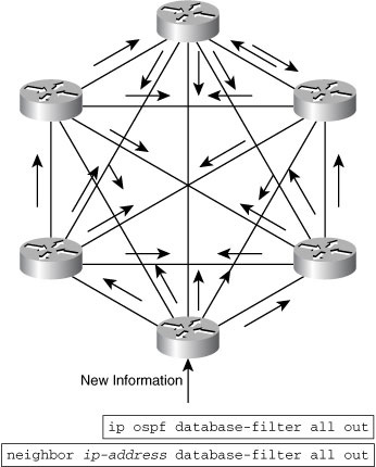
![]() Flooding within an OSPF full mesh is complex and does not scale well. Each router will have to talk to each of its neighbors. Each router will receive at least one copy of every new piece of information from each neighbor on the full mesh.
Flooding within an OSPF full mesh is complex and does not scale well. Each router will have to talk to each of its neighbors. Each router will receive at least one copy of every new piece of information from each neighbor on the full mesh.
![]() One technique that enables you to reduce the amount of flooding in a full-mesh network is to establish mesh groups. The mesh group is deployed by manually configuring OSPF behavior to act as if specific DRs are present by suppressing LSA flooding from all routers not designated as a DR. The specific approach is to pick at least two of the routers that will flood into the mesh, and then use filters to block flooding out of all the other routers. Flooding into all routers remains open.
One technique that enables you to reduce the amount of flooding in a full-mesh network is to establish mesh groups. The mesh group is deployed by manually configuring OSPF behavior to act as if specific DRs are present by suppressing LSA flooding from all routers not designated as a DR. The specific approach is to pick at least two of the routers that will flood into the mesh, and then use filters to block flooding out of all the other routers. Flooding into all routers remains open.
| Note |
|
![]() On broadcast, nonbroadcast, and point-to-point networks, use the ip ospf database-filter all out command in interface configuration mode to configure the routers not acting as DRs and prevent flooding of OSPF LSAs. On point-to-multipoint networks, use the neighbor ip-address database-filter all out command in router configuration mode. Both of these commands are available in Cisco IOS Software Release 12.0 and later.
On broadcast, nonbroadcast, and point-to-point networks, use the ip ospf database-filter all out command in interface configuration mode to configure the routers not acting as DRs and prevent flooding of OSPF LSAs. On point-to-multipoint networks, use the neighbor ip-address database-filter all out command in router configuration mode. Both of these commands are available in Cisco IOS Software Release 12.0 and later.
| Note |
|
OSPF Flooding Reduction
![]() OSPF Flooding Reduction is a feature that you can implement when LSA flooding is having too great an impact on CPU or bandwidth. OSPF Flooding Reduction is a derivative of OSPF demand circuits, discussed in RFC 1793, based on DoNotAge (DNA) LSAs. RFC 4136 extends the nonaging behavior of demand circuits to all interface types. This feature is configured at the interface level with the ip ospf flood-reduction configuration command. This command is available in Cisco IOS Software Release 12.1(2)T and later.
OSPF Flooding Reduction is a feature that you can implement when LSA flooding is having too great an impact on CPU or bandwidth. OSPF Flooding Reduction is a derivative of OSPF demand circuits, discussed in RFC 1793, based on DoNotAge (DNA) LSAs. RFC 4136 extends the nonaging behavior of demand circuits to all interface types. This feature is configured at the interface level with the ip ospf flood-reduction configuration command. This command is available in Cisco IOS Software Release 12.1(2)T and later.
![]() The benefit of OSPF Flooding Reduction is that it eliminates the periodic refresh of unchanged LSAs. This means less effort for the routers doing flood reduction and less bandwidth consumed. OSPF Flooding Reduction can be particularly useful in fully meshed topologies. A periodic refresh still provides recovery from any bugs, glitches, or other LSA database inconsistencies.
The benefit of OSPF Flooding Reduction is that it eliminates the periodic refresh of unchanged LSAs. This means less effort for the routers doing flood reduction and less bandwidth consumed. OSPF Flooding Reduction can be particularly useful in fully meshed topologies. A periodic refresh still provides recovery from any bugs, glitches, or other LSA database inconsistencies.
![]() However, OSPF Flooding Reduction is a tool that fixes symptoms rather than the underlying problem. If the OSPF design is such that flood reduction looks attractive or necessary, perhaps that design is not optimized.
However, OSPF Flooding Reduction is a tool that fixes symptoms rather than the underlying problem. If the OSPF design is such that flood reduction looks attractive or necessary, perhaps that design is not optimized.
| Note |
|
![]() Design changes that might reduce the need for OSPF Flooding Reduction include the following:
Design changes that might reduce the need for OSPF Flooding Reduction include the following:
- Reducing the number of routers in an area
- Reducing the number of adjacencies for stressed routers
- Decreasing the volatility of the network, or reduce area sizes in response to volatility that is greater than expected
- Spreading the adjacency workload across more routers
- Using more hierarchy rather than large-scale, full-mesh topologies
Fast Convergence in OSPF
![]() The topic looks at fast convergence for routing protocols, with an emphasis on OSPF. OSPF supports subsecond hello timers, which can help support fast convergence in these protocols. OSPF with “tuned timers” converges faster than the default OSPF operation. The OSPF routing protocol supports subsecond hello and dead timers. By comparison, subsecond timers are not available for EIGRP.
The topic looks at fast convergence for routing protocols, with an emphasis on OSPF. OSPF supports subsecond hello timers, which can help support fast convergence in these protocols. OSPF with “tuned timers” converges faster than the default OSPF operation. The OSPF routing protocol supports subsecond hello and dead timers. By comparison, subsecond timers are not available for EIGRP.
| Note |
|
Fast Convergence with Fast Hellos
![]() Scaling is the major issue with fast hellos. If hello timers are set to 1/3 second for 300 interfaces, each with 10 neighbors, the router would have to generate 900 hellos per second. When the 3000 neighbors send 3 hellos per second back to the router, it has to process a total of 9900 hellos per second.
Scaling is the major issue with fast hellos. If hello timers are set to 1/3 second for 300 interfaces, each with 10 neighbors, the router would have to generate 900 hellos per second. When the 3000 neighbors send 3 hellos per second back to the router, it has to process a total of 9900 hellos per second.
![]() However, a good OSPF design limits the number of adjacencies. From that perspective, 300 or 3000 neighbors is too high a number.
However, a good OSPF design limits the number of adjacencies. From that perspective, 300 or 3000 neighbors is too high a number.
![]() The design conclusion is use fast hellos only in scenarios with a moderate numbers of neighbors. You can also test and observe the impact of fast hellos on a particular router CPU.
The design conclusion is use fast hellos only in scenarios with a moderate numbers of neighbors. You can also test and observe the impact of fast hellos on a particular router CPU.
Fast Convergence with SPF
![]() The key to OSPF fast convergence is based on a full understanding the Shortest Path First algorithm (SPF).
The key to OSPF fast convergence is based on a full understanding the Shortest Path First algorithm (SPF).
![]() Understanding fast convergence in OSPF requires examining when full or partial SPF calculations are triggered and how fast SPF completes its calculations. Lab testing suggests that the SPF calculation is the biggest remaining source of delay in OSPF convergence, when a lack of hellos detects neighbor loss. Link-down conditions are generally detected more quickly, because of a loss of voltage or media keepalives.
Understanding fast convergence in OSPF requires examining when full or partial SPF calculations are triggered and how fast SPF completes its calculations. Lab testing suggests that the SPF calculation is the biggest remaining source of delay in OSPF convergence, when a lack of hellos detects neighbor loss. Link-down conditions are generally detected more quickly, because of a loss of voltage or media keepalives.
![]() Full SPF calculations depend on the number of nodes and links in the area, and the number of Type 3 to Type 7 LSAs in the OSPF database. The figure presents some experimental numbers for full and partial SPF convergence times on Cisco 12000 series and Cisco 7500 series routers. As expected, SPF calculation time increases for additional nodes. Partial SPF is much faster than full SPF.
Full SPF calculations depend on the number of nodes and links in the area, and the number of Type 3 to Type 7 LSAs in the OSPF database. The figure presents some experimental numbers for full and partial SPF convergence times on Cisco 12000 series and Cisco 7500 series routers. As expected, SPF calculation time increases for additional nodes. Partial SPF is much faster than full SPF.
Overview of OSPF Incremental SPF
![]() A feature known as incremental SPF (iSPF) provides more rapid SPF computations. The iSPF computation uses a modified Dijkstra algorithm to recompute only the part of the path tree that has changed. The algorithm recomputes only a portion of the tree rather than the entire tree and results in faster OSPF convergence and saves CPU resources.
A feature known as incremental SPF (iSPF) provides more rapid SPF computations. The iSPF computation uses a modified Dijkstra algorithm to recompute only the part of the path tree that has changed. The algorithm recomputes only a portion of the tree rather than the entire tree and results in faster OSPF convergence and saves CPU resources.
![]() The performance gain of iSPF depends on how far topologically the change happens from the calculating node or how much of the SPF tree remains unchanged. If the change is far away from the node performing iSPF, the SPF tree is likely to remain mostly unchanged, in which case SPF calculation will be very fast, resulting in faster networkwide convergence. If the change is close to the iSPF node, more of the shortest path tree (SPT) will change. In that case, iSPF provides less benefit.
The performance gain of iSPF depends on how far topologically the change happens from the calculating node or how much of the SPF tree remains unchanged. If the change is far away from the node performing iSPF, the SPF tree is likely to remain mostly unchanged, in which case SPF calculation will be very fast, resulting in faster networkwide convergence. If the change is close to the iSPF node, more of the shortest path tree (SPT) will change. In that case, iSPF provides less benefit.
![]() Lab testing indicates a router can run iSPF and update the routing table for the 1000-node network in less than 10 ms, which would improve OSPF convergence.
Lab testing indicates a router can run iSPF and update the routing table for the 1000-node network in less than 10 ms, which would improve OSPF convergence.
![]() Topology changes cause less and less impact or computational delay the farther away a node is from where the change occurred. iSPF does not add a constant and large delay to propagating change LSAs, as full SPF does. Instead, with iSPF there is a dampening effect, where the larger the LSA propagation delay is, the less computational delay there will be in addition. This is a general observation, and specific results will vary depending on network topology.
Topology changes cause less and less impact or computational delay the farther away a node is from where the change occurred. iSPF does not add a constant and large delay to propagating change LSAs, as full SPF does. Instead, with iSPF there is a dampening effect, where the larger the LSA propagation delay is, the less computational delay there will be in addition. This is a general observation, and specific results will vary depending on network topology.
![]() The iSPF feature has been available since Cisco IOS Software Release 12.0(24)S, 12.3(2)T, 12.2(18)S, and 12.2(27)SBC. It is enabled with the iSPF router command under an OSPF process.
The iSPF feature has been available since Cisco IOS Software Release 12.0(24)S, 12.3(2)T, 12.2(18)S, and 12.2(27)SBC. It is enabled with the iSPF router command under an OSPF process.
Incremental SPF Convergence Times
![]() This section provides some experimental results from testing iSPF convergence times.
This section provides some experimental results from testing iSPF convergence times.
![]() Figure 3-21 illustrates some iSPF convergence times from Cisco lab experiments. The diagram shows normal SPF and iSPF convergence times for multiples of 2000 nodes in a link flap scenario. Even for around 10,000 nodes, iSPF achieved approximately 50-ms convergence, which is extremely fast. For large networks, iSPF can provide significant savings in CPU resources and faster OSPF convergence.
Figure 3-21 illustrates some iSPF convergence times from Cisco lab experiments. The diagram shows normal SPF and iSPF convergence times for multiples of 2000 nodes in a link flap scenario. Even for around 10,000 nodes, iSPF achieved approximately 50-ms convergence, which is extremely fast. For large networks, iSPF can provide significant savings in CPU resources and faster OSPF convergence.


Bidirectional Forwarding Detection
![]() Bidirectional Forwarding Detection (BFD) is another feature that helps speed up routing convergence. One of the significant factors in routing convergence is the detection of link or node failure. In the case of link failures, there is usually an electrical signal or keepalive to detect the loss of the link. BFD is a technology that uses fast Layer 2 link hellos to detect failed or one-way links, which is generally what fast hellos detect.
Bidirectional Forwarding Detection (BFD) is another feature that helps speed up routing convergence. One of the significant factors in routing convergence is the detection of link or node failure. In the case of link failures, there is usually an electrical signal or keepalive to detect the loss of the link. BFD is a technology that uses fast Layer 2 link hellos to detect failed or one-way links, which is generally what fast hellos detect.
![]() BFD requires routing-protocol support. BFD is available for OSPF, EIGRP, IS-IS, and BGP. BFD quickly notifies the routing protocol of link-down conditions. This can provide failure detection and response times down to around 50 ms, which is the typical SONET failure response time.
BFD requires routing-protocol support. BFD is available for OSPF, EIGRP, IS-IS, and BGP. BFD quickly notifies the routing protocol of link-down conditions. This can provide failure detection and response times down to around 50 ms, which is the typical SONET failure response time.
![]() The CPU impact of BFD is less than that of fast hellos. This is because some of the processing is shifted to the data plane rather than the control plane. On nondistributed platforms, Cisco testing has shown a minor, 2 percent CPU increase above baseline when supporting 100 concurrent BFD sessions.
The CPU impact of BFD is less than that of fast hellos. This is because some of the processing is shifted to the data plane rather than the control plane. On nondistributed platforms, Cisco testing has shown a minor, 2 percent CPU increase above baseline when supporting 100 concurrent BFD sessions.
![]() BFD provides a method for network administrators to configure subsecond Layer 2 failure detection between adjacent network nodes. Furthermore, administrators can configure their routing protocols to respond to BFD notifications and begin Layer 3 route convergence almost immediately.
BFD provides a method for network administrators to configure subsecond Layer 2 failure detection between adjacent network nodes. Furthermore, administrators can configure their routing protocols to respond to BFD notifications and begin Layer 3 route convergence almost immediately.
| Note |
|
0 comments
Post a Comment