First-Hop Redundancy
![]() First-hop redundancy or default-gateway redundancy is an important component in convergence in a highly available hierarchical network design.
First-hop redundancy or default-gateway redundancy is an important component in convergence in a highly available hierarchical network design.
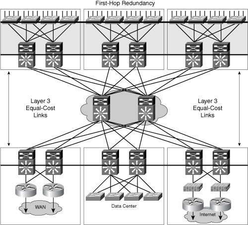
![]() First-hop redundancy allows a network to recover from the failure of the device acting as the default gateway for end nodes on a physical segment. When the access layer is Layer 2, the distribution layer switches act as the default gateway for the entire Layer 2 domain that they support, as illustrated in Figure 2-16.
First-hop redundancy allows a network to recover from the failure of the device acting as the default gateway for end nodes on a physical segment. When the access layer is Layer 2, the distribution layer switches act as the default gateway for the entire Layer 2 domain that they support, as illustrated in Figure 2-16.
![]() A first-hop redundancy protocol is needed only if the design implements Layer 2 between the access switch and the distribution switch. If Layer 3 is supported to the access switch, the default gateway for end devices is at the access level.
A first-hop redundancy protocol is needed only if the design implements Layer 2 between the access switch and the distribution switch. If Layer 3 is supported to the access switch, the default gateway for end devices is at the access level.
![]() In Cisco deployments, HSRP, developed by Cisco, is typically used as the FHRP. VRRP is an Internet Engineering Task Force (IETF) standards-based method of providing default-gateway redundancy. More deployments are starting to use GLBP, which can more easily achieve load balancing on the uplinks from the access layer to the distribution layer, and first-hop redundancy and failure protection.
In Cisco deployments, HSRP, developed by Cisco, is typically used as the FHRP. VRRP is an Internet Engineering Task Force (IETF) standards-based method of providing default-gateway redundancy. More deployments are starting to use GLBP, which can more easily achieve load balancing on the uplinks from the access layer to the distribution layer, and first-hop redundancy and failure protection.
![]() HSRP and VRRP with Cisco enhancements both provide a robust method of backing up the default gateway, and can provide subsecond failover to the redundant distribution switch when tuned properly. HSRP is the recommended protocol over VRRP because it is a Cisco-owned standard, which allows for the rapid development of new features and functionality before VRRP. VRRP is the logical choice over HSRP when interoperability with other vendor devices is required.
HSRP and VRRP with Cisco enhancements both provide a robust method of backing up the default gateway, and can provide subsecond failover to the redundant distribution switch when tuned properly. HSRP is the recommended protocol over VRRP because it is a Cisco-owned standard, which allows for the rapid development of new features and functionality before VRRP. VRRP is the logical choice over HSRP when interoperability with other vendor devices is required.
![]() HSRP or GLBP timers can be reliably tuned to achieve 800-ms convergence for link or node failure in the Layer 2 and Layer 3 boundary in the building distribution layer. The following configuration snippet shows how HSRP can be tuned down from its default 3-second hello timer and 10-second hold timer in a campus environment to achieve subsecond convergence on aggregation switches:
HSRP or GLBP timers can be reliably tuned to achieve 800-ms convergence for link or node failure in the Layer 2 and Layer 3 boundary in the building distribution layer. The following configuration snippet shows how HSRP can be tuned down from its default 3-second hello timer and 10-second hold timer in a campus environment to achieve subsecond convergence on aggregation switches:
interface Vlan5
ip address 10.1.5.3 255.255.255.0
ip helper-address 10.5.10.20
standby 1 ip 10.1.5.1
standby 1 timers msec 200 msec 750
standby 1 priority 150
standby 1 preempt delay minimum 180
 Preempt Delay Tuning
![]() One important factor to take into account when tuning default gateway redundancy using HSRP or another protocol is its preemptive behavior.
One important factor to take into account when tuning default gateway redundancy using HSRP or another protocol is its preemptive behavior.
![]() Preemption causes the primary HSRP peer to re-assume the primary role when it comes back online after a failure or maintenance event. Preemption is the desired behavior because the RSTP root should be the same device as the HSRP primary for a given subnet or VLAN. However, if HSRP and RSTP are not synchronized after failure recovery, the interconnection between the distribution switches can become a transit link, and traffic takes a multihop Layer 2 path to its default gateway.
Preemption causes the primary HSRP peer to re-assume the primary role when it comes back online after a failure or maintenance event. Preemption is the desired behavior because the RSTP root should be the same device as the HSRP primary for a given subnet or VLAN. However, if HSRP and RSTP are not synchronized after failure recovery, the interconnection between the distribution switches can become a transit link, and traffic takes a multihop Layer 2 path to its default gateway.
![]() HSRP preemption needs to be aware of switch boot time and connectivity to the rest of the network. Preempt delay must be longer than the switch boot time:
HSRP preemption needs to be aware of switch boot time and connectivity to the rest of the network. Preempt delay must be longer than the switch boot time:
-
 Layer 1 traffic forwarding on line cards
 -
 Layer 2 STP convergence
 -
 Layer 3 IGP convergence
![]() It is possible for HSRP neighbor relationships to form and preemption to occur before the primary switch has Layer 3 connectivity to the core. If this happens, traffic from the access layer can be dropped until full connectivity is established to the core.
It is possible for HSRP neighbor relationships to form and preemption to occur before the primary switch has Layer 3 connectivity to the core. If this happens, traffic from the access layer can be dropped until full connectivity is established to the core.
![]() The recommended practice is to measure the system boot time, and set the HSRP preempt delay with the standby preempt delay minimum command to 50 percent greater than this value. This ensures that the HSRP primary distribution node has established full connectivity to all parts of the network before HSRP preemption is allowed to occur.
The recommended practice is to measure the system boot time, and set the HSRP preempt delay with the standby preempt delay minimum command to 50 percent greater than this value. This ensures that the HSRP primary distribution node has established full connectivity to all parts of the network before HSRP preemption is allowed to occur.
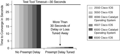
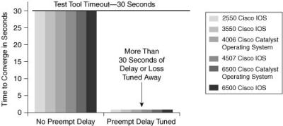
![]() Figure 2-17 demonstrates the positive impact that proper HSRP tuning can have on network convergence.
Figure 2-17 demonstrates the positive impact that proper HSRP tuning can have on network convergence.
 Overview of Gateway Load Balancing Protocol
![]() GLBP is a first-hop redundancy protocol designed by Cisco that allows packet load sharing between groups of redundant routers.
GLBP is a first-hop redundancy protocol designed by Cisco that allows packet load sharing between groups of redundant routers.
![]() When HSRP or VRRP is used to provide default-gateway redundancy, the backup members of the peer relationship are idle, waiting for a failure event to occur before they take over and actively forward traffic. Methods to use uplinks with HSRP or VRRP are difficult to implement and manage. In one technique, the HSRP and STP or RSTP roots alternate between distribution node peers, with the even VLANs homed on one peer and the odd VLANs homed on the alternate. Another technique uses multiple HSRP groups on a single interface and uses DHCP to alternate between the multiple default gateways. These techniques work but are not optimal from a configuration, maintenance, or management perspective.
When HSRP or VRRP is used to provide default-gateway redundancy, the backup members of the peer relationship are idle, waiting for a failure event to occur before they take over and actively forward traffic. Methods to use uplinks with HSRP or VRRP are difficult to implement and manage. In one technique, the HSRP and STP or RSTP roots alternate between distribution node peers, with the even VLANs homed on one peer and the odd VLANs homed on the alternate. Another technique uses multiple HSRP groups on a single interface and uses DHCP to alternate between the multiple default gateways. These techniques work but are not optimal from a configuration, maintenance, or management perspective.
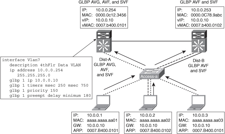
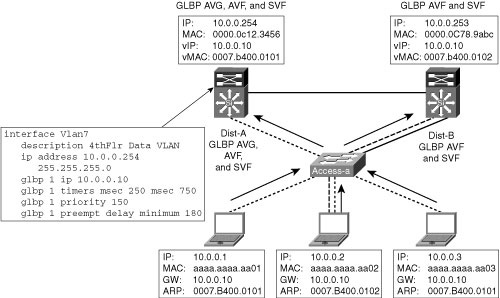
![]() GLBP provides all the benefits of HSRP and includes load balancing, too. For HSRP, a single virtual MAC address is given to the endpoints when the endpoints use Address Resolution Protocol (ARP) to learn the physical MAC address of their default gateways. GLBP allows a group of routers to function as one virtual router by sharing one virtual IP address while using multiple virtual MAC addresses for traffic forwarding. Figure 2-18 shows a sample configuration supporting GLBP and its roles.
GLBP provides all the benefits of HSRP and includes load balancing, too. For HSRP, a single virtual MAC address is given to the endpoints when the endpoints use Address Resolution Protocol (ARP) to learn the physical MAC address of their default gateways. GLBP allows a group of routers to function as one virtual router by sharing one virtual IP address while using multiple virtual MAC addresses for traffic forwarding. Figure 2-18 shows a sample configuration supporting GLBP and its roles.
![]() When an endpoint uses ARP for its default gateway, by default the virtual MACs are provided by the GLBP active virtual gateway (AVG) on a round-robin basis. These gateways that assume responsibility for forwarding packets sent to the virtual MAC address are known as active virtual forwarders (AVF) for their virtual MAC address. Because the traffic from a single common subnet goes through multiple redundant gateways, all the uplinks can be used.
When an endpoint uses ARP for its default gateway, by default the virtual MACs are provided by the GLBP active virtual gateway (AVG) on a round-robin basis. These gateways that assume responsibility for forwarding packets sent to the virtual MAC address are known as active virtual forwarders (AVF) for their virtual MAC address. Because the traffic from a single common subnet goes through multiple redundant gateways, all the uplinks can be used.
![]() Failover and convergence in GLBP work in a similar fashion as HSRP. A secondary virtual forwarder (SVF) takes over for traffic destined to a virtual MAC impacted by the failure and begins forwarding traffic for its failed peer. The end result is that a more equal utilization of the uplinks is achieved with minimal configuration. As a side effect, a convergence event on the uplink or on the primary distribution node affects only half as many hosts with a pair of GLBP switches, giving a convergence event an average of 50 percent less impact.
Failover and convergence in GLBP work in a similar fashion as HSRP. A secondary virtual forwarder (SVF) takes over for traffic destined to a virtual MAC impacted by the failure and begins forwarding traffic for its failed peer. The end result is that a more equal utilization of the uplinks is achieved with minimal configuration. As a side effect, a convergence event on the uplink or on the primary distribution node affects only half as many hosts with a pair of GLBP switches, giving a convergence event an average of 50 percent less impact.
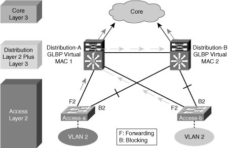
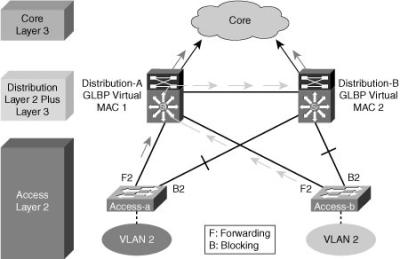
![]() Note that using GLBP in topologies where STP has blocked one of the access layer uplinks may result in a two-hop path at Layer 2 for upstream traffic, as illustrated in Figure 2-19.
Note that using GLBP in topologies where STP has blocked one of the access layer uplinks may result in a two-hop path at Layer 2 for upstream traffic, as illustrated in Figure 2-19.
![]() In environments where VLANs span across the distribution switches, HSRP is the preferred FHRP implementation.
In environments where VLANs span across the distribution switches, HSRP is the preferred FHRP implementation.
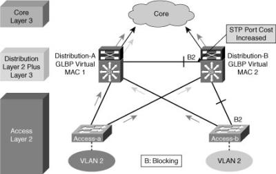
![]() In some cases, the STP environment can be tuned so that the Layer 2 link between the distribution switches is the blocking link while the uplinks from the access layer switches are in a forwarding state.
In some cases, the STP environment can be tuned so that the Layer 2 link between the distribution switches is the blocking link while the uplinks from the access layer switches are in a forwarding state.
![]() Figure 2-20 illustrates how you can tune STP by using the spanning-tree cost interface configuration command to change the port cost on the interface between the distribution layer switches on the STP secondary root switch. This option works if no VLANs span access switches.
Figure 2-20 illustrates how you can tune STP by using the spanning-tree cost interface configuration command to change the port cost on the interface between the distribution layer switches on the STP secondary root switch. This option works if no VLANs span access switches.
![]() However, if the same VLAN is on multiple access switches, you will have a looped figure-eight topology where one access layer uplink is still blocking. The preferred design is to not span VLANs across access switches.
However, if the same VLAN is on multiple access switches, you will have a looped figure-eight topology where one access layer uplink is still blocking. The preferred design is to not span VLANs across access switches.
 Optimizing FHRP Convergence
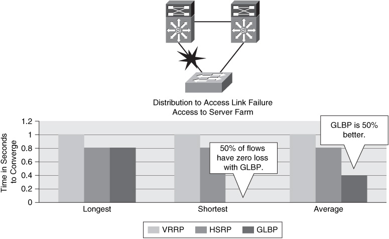
![]() HSRP can be reliably tuned to achieve 800-ms convergence for link or node failure. With HSRP, all flows from one subnet go through the active HSRP router; so the longest, shortest, and average convergence times are the same and less than a second.
HSRP can be reliably tuned to achieve 800-ms convergence for link or node failure. With HSRP, all flows from one subnet go through the active HSRP router; so the longest, shortest, and average convergence times are the same and less than a second.
![]() VRRP can be tuned with subsecond timers, although the results of this timer tuning is not known. With VRRP, all flows from one subnet go through the same VRRP master router, so the longest, shortest, and average convergence times are the same and about a second.
VRRP can be tuned with subsecond timers, although the results of this timer tuning is not known. With VRRP, all flows from one subnet go through the same VRRP master router, so the longest, shortest, and average convergence times are the same and about a second.
![]() GLBP can also be reliably tuned to achieve 800-ms convergence for link or node failure. With GLBP, a convergence event on an uplink or on the primary distribution node affects only half as many hosts, so a convergence event has an average of 50 percent less impact than with HSRP or VRRP if the default round-robin load-balancing algorithm is used.
GLBP can also be reliably tuned to achieve 800-ms convergence for link or node failure. With GLBP, a convergence event on an uplink or on the primary distribution node affects only half as many hosts, so a convergence event has an average of 50 percent less impact than with HSRP or VRRP if the default round-robin load-balancing algorithm is used.
![]() GLBP is currently supported on the Cisco Catalyst 6500 series switches and the Cisco Catalyst 4500 series switches.
GLBP is currently supported on the Cisco Catalyst 6500 series switches and the Cisco Catalyst 4500 series switches.
![]() Figure 2-21 illustrates the difference in convergence times between each of the respective FHRP when deployed on a distribution to access link in a server farm.
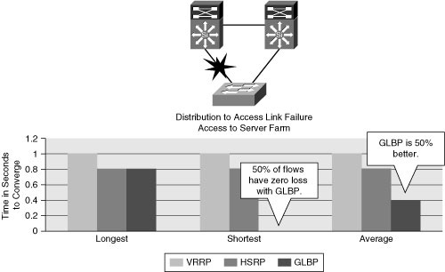
Figure 2-21 illustrates the difference in convergence times between each of the respective FHRP when deployed on a distribution to access link in a server farm.

1 comments
plz anyone give me the load balancing using GLBP project in sop copy..
my Email id : ronaksachdev.scs@gmail.com
plz send the mail...
thank u...
Post a Comment