
Supporting Infrastructure Services
![]() This section reviews considerations for supporting infrastructure services in highly available enterprise campus networks. Considerations for building a converged network to support IP telephony are discussed. QoS attributes and aspects of the Cisco Catalyst Integrated Security features are also described.
This section reviews considerations for supporting infrastructure services in highly available enterprise campus networks. Considerations for building a converged network to support IP telephony are discussed. QoS attributes and aspects of the Cisco Catalyst Integrated Security features are also described.
IP Telephony Considerations
![]() IP telephony services are supported at each layer of the campus network.
IP telephony services are supported at each layer of the campus network.
![]() High availability, redundancy, and fast convergence needed by IP telephony services are supported throughout the enterprise campus network. QoS features are implemented throughout the network. The distribution layer typically supports policy enforcement.
High availability, redundancy, and fast convergence needed by IP telephony services are supported throughout the enterprise campus network. QoS features are implemented throughout the network. The distribution layer typically supports policy enforcement.
![]() However, because implementing IP telephony services extends the network edge, IP telephony has the most impact at the access layer of the network. The access layer supports device attachment and phone detection, inline power for devices, and QoS features including classification, scheduling, and the trust boundary.
However, because implementing IP telephony services extends the network edge, IP telephony has the most impact at the access layer of the network. The access layer supports device attachment and phone detection, inline power for devices, and QoS features including classification, scheduling, and the trust boundary.
 IP Telephony Extends the Network Edge
![]() Because the IP phone is a three-port switch, IP telephony services actually extend the network edge, as shown in Figure 2-33.
Because the IP phone is a three-port switch, IP telephony services actually extend the network edge, as shown in Figure 2-33.


![]() The IP phone shown in Figure 2-33 contains a three-port switch that is configured in conjunction with the access switch and Cisco Unified Communications Manager:
The IP phone shown in Figure 2-33 contains a three-port switch that is configured in conjunction with the access switch and Cisco Unified Communications Manager:
- Power negotiation
- VLAN configuration
- 802.1x interoperation
- QoS configuration
- DHCP and Cisco Unified Communications Manager registration
![]() When a Cisco IP phone is connected to the network, Cisco Catalyst multiservice switches detect and integrate the phone with the network. The switches can deliver Power over Ethernet (PoE) using existing copper cabling to power the IP phones. The switches place the IP phones and attached devices in the appropriate VLAN, often using 802.1x services. The switch supports the QoS configuration needed for the IP phones, and provides connection to DHCP servers and Cisco Unified Communications Manager systems for registration.
When a Cisco IP phone is connected to the network, Cisco Catalyst multiservice switches detect and integrate the phone with the network. The switches can deliver Power over Ethernet (PoE) using existing copper cabling to power the IP phones. The switches place the IP phones and attached devices in the appropriate VLAN, often using 802.1x services. The switch supports the QoS configuration needed for the IP phones, and provides connection to DHCP servers and Cisco Unified Communications Manager systems for registration.
![]() PoE is the ability for the LAN switching infrastructure to provide power over a copper Ethernet cable to an endpoint or powered device. This capability is also referred to as inline power, and was originally developed by Cisco Systems in 2000 to support the emerging IP telephony deployments.
PoE is the ability for the LAN switching infrastructure to provide power over a copper Ethernet cable to an endpoint or powered device. This capability is also referred to as inline power, and was originally developed by Cisco Systems in 2000 to support the emerging IP telephony deployments.
![]() To support PoE delivery to power capable devices, a number of issues need to be resolved: phone detection, power delivery, power management, and cable and bandwidth management.
To support PoE delivery to power capable devices, a number of issues need to be resolved: phone detection, power delivery, power management, and cable and bandwidth management.
PoE Requirements
![]() There are two PoE implementations available, and two ways to provide power to the IP phones:
There are two PoE implementations available, and two ways to provide power to the IP phones:
- Cisco line cards support prestandard PoE, IEEE 802.3af, and a mix of devices. IEEE 802.3af-only devices will not negotiate or receive power from an original Cisco PoE-only line card.
- Cisco devices use a bidirectional Cisco Discovery Protocol (CDP) exchange to negotiate the exact power requirements. Power negotiation optimizes power consumption by allowing the switch to reserve only the power needed for the device.
![]() The earlier Cisco prestandard PoE devices initially receive 6.3W and then optionally negotiate their power requirements using CDP. Cisco prestandard devices use a relay in the powered device to reflect a special FastLink pulse for device detection.
The earlier Cisco prestandard PoE devices initially receive 6.3W and then optionally negotiate their power requirements using CDP. Cisco prestandard devices use a relay in the powered device to reflect a special FastLink pulse for device detection.
![]() The devices based on the IEEE 802.3af power standard initially receive 12.95 watts of power, unless a power-sourcing equipment (PSE) device can detect a specific powered device classification. An 802.3af PSE device applies a voltage in the range of –2.8 to –10 volts on the cable and then looks for a 25K ohm signature resistor in the powered device.
The devices based on the IEEE 802.3af power standard initially receive 12.95 watts of power, unless a power-sourcing equipment (PSE) device can detect a specific powered device classification. An 802.3af PSE device applies a voltage in the range of –2.8 to –10 volts on the cable and then looks for a 25K ohm signature resistor in the powered device.
![]() IEEE 802.3af power may be delivered using a PoE-capable Ethernet port, which is referred to as an endpoint PSE, or by a midspan PSE that can be used to deliver PoE in the event an existing non-PoE-capable Ethernet switch is used. An endpoint PSE, such as a PoE-capable Ethernet switch, can use either active data wires of an Ethernet port or spare wires to a powered device. Some midspan PSEs can only implement power over spare pairs of copper cabling and cannot be used to deliver PoE over 1000BASE-T connections.
IEEE 802.3af power may be delivered using a PoE-capable Ethernet port, which is referred to as an endpoint PSE, or by a midspan PSE that can be used to deliver PoE in the event an existing non-PoE-capable Ethernet switch is used. An endpoint PSE, such as a PoE-capable Ethernet switch, can use either active data wires of an Ethernet port or spare wires to a powered device. Some midspan PSEs can only implement power over spare pairs of copper cabling and cannot be used to deliver PoE over 1000BASE-T connections.
![]() The IEEE 802.3af power standard classes are shown here in Figure 2-34.
The IEEE 802.3af power standard classes are shown here in Figure 2-34.


| Note |
|
Power Budget and Management
![]() Power budget planning is necessary to determine what devices can be supported today and in the future.
Power budget planning is necessary to determine what devices can be supported today and in the future.
![]() The switches manage power by what is allocated, not by what is currently used. However, the device power consumption is not constant:
The switches manage power by what is allocated, not by what is currently used. However, the device power consumption is not constant:
- Cisco Unified IP Phone 7960G requires 7W when the phone is ringing at maximum volume.
- Cisco Unified IP Phone 7960G requires 5W when it is on or off hook.
![]() Delivery of PoE using the IEEE 802.3af default classification may significantly increase the power requirements on both the PSE switch and the power infrastructure. To provide PoE in a cost-effective and efficient manner, Cisco Catalyst switches support Cisco Intelligent Power Management (Cisco IPM) in addition to IEEE 802.3af classification. This enables a powered device and PSE to negotiate their respective capabilities to explicitly manage how much power is required to power the device and also how the PSE-capable switch manages the allocation of power to individual powered devices. These Cisco IPM capabilities enable a network and facilities manager to effectively and economically manage the power resources within a wiring closet and help PSE-capable switches meet the objectives of the network.
Delivery of PoE using the IEEE 802.3af default classification may significantly increase the power requirements on both the PSE switch and the power infrastructure. To provide PoE in a cost-effective and efficient manner, Cisco Catalyst switches support Cisco Intelligent Power Management (Cisco IPM) in addition to IEEE 802.3af classification. This enables a powered device and PSE to negotiate their respective capabilities to explicitly manage how much power is required to power the device and also how the PSE-capable switch manages the allocation of power to individual powered devices. These Cisco IPM capabilities enable a network and facilities manager to effectively and economically manage the power resources within a wiring closet and help PSE-capable switches meet the objectives of the network.
![]() Power management is complex. Power management can have significant ramifications with respect to the power supply required to drive all the powered devices and line cards, how power is delivered within the switch, how the switch manages power allocation, and finally, for the power delivery requirements of the wiring closet. You need to plan for maximum theoretical draw that so there will be sufficient power available to be allocated to end devices and the line cards in the switch. Even if the PSE and powered device support power classification, the classification ranges are fairly broad and can lead to wasted power budget allocation. When there is insufficient power in a chassis, the power management system will deactivate line cards.
Power management is complex. Power management can have significant ramifications with respect to the power supply required to drive all the powered devices and line cards, how power is delivered within the switch, how the switch manages power allocation, and finally, for the power delivery requirements of the wiring closet. You need to plan for maximum theoretical draw that so there will be sufficient power available to be allocated to end devices and the line cards in the switch. Even if the PSE and powered device support power classification, the classification ranges are fairly broad and can lead to wasted power budget allocation. When there is insufficient power in a chassis, the power management system will deactivate line cards.
![]() Power requirements can be estimated using the Cisco Power Calculator found at http://tools.cisco.com/cpc/launch.jsp.
Power requirements can be estimated using the Cisco Power Calculator found at http://tools.cisco.com/cpc/launch.jsp.
![]() The Cisco Power Calculator enables you to estimate the power supply requirements for a specific PoE and line card configuration.
The Cisco Power Calculator enables you to estimate the power supply requirements for a specific PoE and line card configuration.
![]() The Cisco Power Calculator requires a username and password. The tool allows a series of selections for the configurable products, and provides results showing the output current, output power, and system heat dissipation for a specific configuration.
The Cisco Power Calculator requires a username and password. The tool allows a series of selections for the configurable products, and provides results showing the output current, output power, and system heat dissipation for a specific configuration.
![]() The calculator is an educational resource and a starting point in planning power requirements; it does not provide a final power recommendation from Cisco.
The calculator is an educational resource and a starting point in planning power requirements; it does not provide a final power recommendation from Cisco.
![]() The Cisco Power Calculator supports the following Cisco product series: Cisco Catalyst 6500, Catalyst 4500, Catalyst 3750, and Catalyst 3560 series switches, and the Cisco 7600 series router.
The Cisco Power Calculator supports the following Cisco product series: Cisco Catalyst 6500, Catalyst 4500, Catalyst 3750, and Catalyst 3560 series switches, and the Cisco 7600 series router.
![]() The Power Consumption Summary screen shown in Figure 2-35 displays the minimum power supply required for the selected configuration and percentage of power usage. The table displays output current (amperes), output power (watts), and heat dissipation (BTUs per hour).
The Power Consumption Summary screen shown in Figure 2-35 displays the minimum power supply required for the selected configuration and percentage of power usage. The table displays output current (amperes), output power (watts), and heat dissipation (BTUs per hour).


![]() The Cisco Power Calculator recommends the smallest power supply that meets the requirements of the configuration. The tool reports single and redundant power supply options, and also the combined power configuration mode as appropriate.
The Cisco Power Calculator recommends the smallest power supply that meets the requirements of the configuration. The tool reports single and redundant power supply options, and also the combined power configuration mode as appropriate.
![]() The power supply details area shown here in Figure 2-36 displays power utilization with various-sized power supplies.
The power supply details area shown here in Figure 2-36 displays power utilization with various-sized power supplies.


![]() The Configuration Details section of the Cisco Power Calculator output shown in Figure 2-37 displays the current, power, and heat dissipation for each component.
The Configuration Details section of the Cisco Power Calculator output shown in Figure 2-37 displays the current, power, and heat dissipation for each component.


Multi-VLAN Access Port
![]() The concept of an access port has been extended to a multi-VLAN access port in the enterprise campus.
The concept of an access port has been extended to a multi-VLAN access port in the enterprise campus.
![]() Multiservice switches support a new parameter for IP telephony support that makes the access port a multi-VLAN access port. The new parameter is called an auxiliary VLAN. Every Ethernet 10/100/1000 port in the switch is associated with two VLANs:
Multiservice switches support a new parameter for IP telephony support that makes the access port a multi-VLAN access port. The new parameter is called an auxiliary VLAN. Every Ethernet 10/100/1000 port in the switch is associated with two VLANs:
- A native VLAN for data service that is identified by the port VLAN ID (PVID)
- An auxiliary VLAN for voice service that is identified by the voice VLAN ID (VVID)
- During the initial CDP exchange with the access switch, the IP phone is configured with a VVID.
- The IP phone is also supplied with a QoS configuration using CDP. Voice traffic is separated from data and supports a different trust boundary.
![]() Data packets between the multiservice access switch and the PC or workstation are on the native VLAN. All packets going out on the native VLAN of an IEEE 802.1Q port are sent untagged by the access switch. The PC or workstation connected to the IP phone usually sends untagged packets.
Data packets between the multiservice access switch and the PC or workstation are on the native VLAN. All packets going out on the native VLAN of an IEEE 802.1Q port are sent untagged by the access switch. The PC or workstation connected to the IP phone usually sends untagged packets.
![]() Voice packets are tagged by the IP phone based on the CDP information from the access switch.
Voice packets are tagged by the IP phone based on the CDP information from the access switch.
![]() The multi-VLAN access ports are not trunk ports, even though the hardware is set to the dot1q trunk. The hardware setting is used to carry more than one VLAN, but the port is still considered an access port that is able to carry one native VLAN and the auxiliary VLAN. The switchport host command can be applied to a multi-VLAN access port on the access switch.
The multi-VLAN access ports are not trunk ports, even though the hardware is set to the dot1q trunk. The hardware setting is used to carry more than one VLAN, but the port is still considered an access port that is able to carry one native VLAN and the auxiliary VLAN. The switchport host command can be applied to a multi-VLAN access port on the access switch.
| Note |
|
QoS Considerations
![]() Typical campus networks are built with oversubscription in mind. The network usually has multiple possible congestion points where important traffic may be dropped without QoS.
Typical campus networks are built with oversubscription in mind. The network usually has multiple possible congestion points where important traffic may be dropped without QoS.
![]() Most campus links are underutilized. Some studies have shown that 95 percent of campus access layer links are utilized at less than 5 percent of their capacity.
Most campus links are underutilized. Some studies have shown that 95 percent of campus access layer links are utilized at less than 5 percent of their capacity.
![]() The rule-of-thumb recommendation for data oversubscription is 20:1 for access ports on the access-to-distribution uplink. The recommendation is 4:1 for the distribution-to-core links. When you use these oversubscription ratios, congestion may occur infrequently on the uplinks. QoS is needed for these occasions. If congestion is frequently occurring, the design does not have sufficient uplink bandwidth.
The rule-of-thumb recommendation for data oversubscription is 20:1 for access ports on the access-to-distribution uplink. The recommendation is 4:1 for the distribution-to-core links. When you use these oversubscription ratios, congestion may occur infrequently on the uplinks. QoS is needed for these occasions. If congestion is frequently occurring, the design does not have sufficient uplink bandwidth.
Recommended Practices for QoS
![]() QoS helps manage oversubscription and speed-transitions in the design. The following are recommended best practices for QoS:
QoS helps manage oversubscription and speed-transitions in the design. The following are recommended best practices for QoS:
- Deployed end-to-end to be effective
- Ensures that mission-critical applications are not impacted by link or transmit queue congestion
- Enforces QoS policies at aggregation and rate transition points
- Uses multiple queues with configurable admission criteria, and scheduling effective QoS is deployed end-to-end with each layer supporting a role
![]() Internet worms and denial-of-service (DoS) attacks can flood links even in a high-speed campus environment. QoS policies protect voice, video, and mission-critical data traffic while giving a lower class of service to suspect traffic.
Internet worms and denial-of-service (DoS) attacks can flood links even in a high-speed campus environment. QoS policies protect voice, video, and mission-critical data traffic while giving a lower class of service to suspect traffic.
![]() Aggregation and rate transition points must enforce QoS policies to support preferred traffic and manage congestion. In campus networks, multiple queues with configurable admission criteria and scheduling are required on the LAN ports.
Aggregation and rate transition points must enforce QoS policies to support preferred traffic and manage congestion. In campus networks, multiple queues with configurable admission criteria and scheduling are required on the LAN ports.
Transmit Queue Congestion
![]() The type of congestion that is most common in a campus network is called transmit-queue (Tx-queue) starvation.
The type of congestion that is most common in a campus network is called transmit-queue (Tx-queue) starvation.
![]() Both LANs and WANs are subject to Tx-queue congestion:
Both LANs and WANs are subject to Tx-queue congestion:
- During a transition from LAN to WAN, a router has to make the rate transition from 10/100 Ethernet to WAN speeds. When this happens, the router must queue the packets and apply QoS to ensure that important traffic is transmitted first. Tx-queue starvation occurs when incoming packets are received faster than outgoing packets are transmitted. Packets are queued as they wait to serialize out onto the slower link.
- In the campus, as the LAN infrastructure transitions from 10 Gb/s or 1 Gb/s uplinks in the distribution layer to 10/100 Gb/s to the desktop, packets must be queued as they wait to serialize out the 10 or 100 Mb/s link.
![]() The difference between a WAN router and a campus switch is the number of interfaces and the amount of memory associated with each. In the campus, the amount of Tx-queue space is much smaller than the amount of memory available in a WAN router. Because of the small amount of memory, the potential for dropped traffic because of Tx-queue starvation is relatively high.
The difference between a WAN router and a campus switch is the number of interfaces and the amount of memory associated with each. In the campus, the amount of Tx-queue space is much smaller than the amount of memory available in a WAN router. Because of the small amount of memory, the potential for dropped traffic because of Tx-queue starvation is relatively high.
QoS Role in the Campus
![]() QoS features are used to prioritize traffic according to its relative importance and provide preferential treatment using congestion management techniques.
QoS features are used to prioritize traffic according to its relative importance and provide preferential treatment using congestion management techniques.
![]() Using QoS in the campus network design ensures that important traffic such as voice and video is placed in a queue that is configured so that it optimizes memory usage.
Using QoS in the campus network design ensures that important traffic such as voice and video is placed in a queue that is configured so that it optimizes memory usage.
![]() However, the network should provide an adequate level of service for all network traffic, including lower-priority, best-effort traffic under normal circumstances. For best-effort traffic, there is an implied good-faith commitment that there are at least some network resources available.
However, the network should provide an adequate level of service for all network traffic, including lower-priority, best-effort traffic under normal circumstances. For best-effort traffic, there is an implied good-faith commitment that there are at least some network resources available.
![]() QoS is also needed to identify and potentially punish out-of-profile traffic such as potential worms, distributed denial of service (DDoS) attacks, and peer-to-peer media-sharing applications that may be placed in a scavenger class and marked with differentiated services code point (DSCP) class selector 1 (CS1). The scavenger class is intended to provide deferential services, or less-than best-effort services, to certain applications. During periods of congestion, scavenger-class traffic is the first to experience Tx-queue starvation and packet loss when the bandwidth is reserved for higher-priority traffic. As demand increases or capacity is reduced, best-effort traffic may also be affected. The minimum goal of high-availability network design is to ensure that high-priority voice, video, and mission-critical data applications are never affected by network congestion.
QoS is also needed to identify and potentially punish out-of-profile traffic such as potential worms, distributed denial of service (DDoS) attacks, and peer-to-peer media-sharing applications that may be placed in a scavenger class and marked with differentiated services code point (DSCP) class selector 1 (CS1). The scavenger class is intended to provide deferential services, or less-than best-effort services, to certain applications. During periods of congestion, scavenger-class traffic is the first to experience Tx-queue starvation and packet loss when the bandwidth is reserved for higher-priority traffic. As demand increases or capacity is reduced, best-effort traffic may also be affected. The minimum goal of high-availability network design is to ensure that high-priority voice, video, and mission-critical data applications are never affected by network congestion.
Campus QoS Design Considerations
![]() Campus QoS design is primarily concerned with classification, marking, and policing, as illustrated in Figure 2-38.
Campus QoS design is primarily concerned with classification, marking, and policing, as illustrated in Figure 2-38.
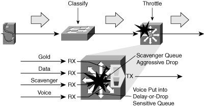
![]() Queuing is enabled at any node that has the potential for congestion. The edge traffic classification scheme is mapped to the upstream queue configuration. The applications are classified and marked as close to their sources as technically and administratively feasible. Traffic flows are policed as close to their sources as possible.
Queuing is enabled at any node that has the potential for congestion. The edge traffic classification scheme is mapped to the upstream queue configuration. The applications are classified and marked as close to their sources as technically and administratively feasible. Traffic flows are policed as close to their sources as possible.
![]() Multiple queues are the only way to guarantee voice quality, protect mission-critical data, and throttle abnormal sources:
Multiple queues are the only way to guarantee voice quality, protect mission-critical data, and throttle abnormal sources:
- Voice needs to be assigned to the hardware priority queue. VoIP deployments require provisioning-explicit priority servicing for VoIP traffic and a guaranteed bandwidth service for call-signaling traffic. Strict-priority queuing is limited to 33 percent of the capacity of the link.
- At least 25 percent of the bandwidth of the link is reserved for the default best-effort class, which is the default class for data traffic. Under normal circumstances, the network should provide an adequate level of service for best-effort traffic.
- Scavenger traffic needs to be assigned its own queue with a low threshold to trigger aggressive drops. Applications assigned to this class have little or no contribution to the organizational objectives of the enterprise. Assigning a minimal bandwidth queue to scavenger traffic forces it to be squelched to virtually nothing during periods of congestion, but allows it to be available if bandwidth is not being used for business purposes, which might occur during off-peak hours.
Cisco Catalyst Integrated Security Features
![]() The Cisco Catalyst Integrated Security capabilities provide campus security on the Cisco Catalyst switches through the use of integrated tools:
The Cisco Catalyst Integrated Security capabilities provide campus security on the Cisco Catalyst switches through the use of integrated tools:
- Port security prevents MAC flooding attacks.
- DHCP snooping prevents client attacks on the DHCP server and switch.
- Dynamic ARP Inspection adds security to ARP using the DHCP snooping table to minimize the impact of ARP poisoning and spoofing attacks.
- IP Source Guard prevents IP spoofing addresses using the DHCP snooping table.
Port Security Prevents MAC-Based Attacks
![]() Port security can be used to prevent MAC-based attacks.
Port security can be used to prevent MAC-based attacks.
![]() A MAC-based attack occurs when an attacker sends out floods of MAC addresses to a switch to overload the CAM table. When the CAM table limit is reached, the switch can no longer keep track of legitimate addresses and starts flooding all information to all ports.
A MAC-based attack occurs when an attacker sends out floods of MAC addresses to a switch to overload the CAM table. When the CAM table limit is reached, the switch can no longer keep track of legitimate addresses and starts flooding all information to all ports.
![]() Port security enables a network administrator to restrict the MAC addresses allowed or the maximum number of MAC addresses on a per-port basis. The allowed MAC addresses on a given port can be either statically configured by the administrator or dynamically learned by the switch. A security violation occurs when either the maximum number of MAC addresses on a given port is exceeded or a frame with a nonsecure source MAC address is seen on that port. The port is then shut down, or alternatively, a Simple Network Management Protocol (SNMP) trap is generated. Aging with either inactivity or a predefined time interval can be configured with port security for the dynamic or static secure MAC addresses.
Port security enables a network administrator to restrict the MAC addresses allowed or the maximum number of MAC addresses on a per-port basis. The allowed MAC addresses on a given port can be either statically configured by the administrator or dynamically learned by the switch. A security violation occurs when either the maximum number of MAC addresses on a given port is exceeded or a frame with a nonsecure source MAC address is seen on that port. The port is then shut down, or alternatively, a Simple Network Management Protocol (SNMP) trap is generated. Aging with either inactivity or a predefined time interval can be configured with port security for the dynamic or static secure MAC addresses.
| Note |
|
DHCP Snooping Protects Against Rogue and Malicious DHCP Servers
![]() DHCP snooping can be used to protect against rogue and malicious DHCP servers.
DHCP snooping can be used to protect against rogue and malicious DHCP servers.
![]() In some cases, an intruder can attach a server to the network and have it assume the role of the DHCP server for that segment. This enables the intruder to give out false DHCP information for the default gateway and domain name servers, which points clients to the hacker’s machine. This misdirection enables the hacker to become a “man in the middle” and to gain access to confidential information, such as username and password pairs, while the end user is unaware of the attack. DHCP snooping can prevent this. DHCP snooping is a per-port security mechanism used to differentiate an untrusted switch port connected to an end user from a trusted switch port connected to a DHCP server or another switch. It can be enabled on a per-VLAN basis. DHCP snooping allows only authorized DHCP servers to respond to DHCP requests and to distribute network information to clients. It also provides the ability to rate-limit DHCP request on client ports, thereby mitigating the effect of DHCP DoS attacks from an individual client or access port.
In some cases, an intruder can attach a server to the network and have it assume the role of the DHCP server for that segment. This enables the intruder to give out false DHCP information for the default gateway and domain name servers, which points clients to the hacker’s machine. This misdirection enables the hacker to become a “man in the middle” and to gain access to confidential information, such as username and password pairs, while the end user is unaware of the attack. DHCP snooping can prevent this. DHCP snooping is a per-port security mechanism used to differentiate an untrusted switch port connected to an end user from a trusted switch port connected to a DHCP server or another switch. It can be enabled on a per-VLAN basis. DHCP snooping allows only authorized DHCP servers to respond to DHCP requests and to distribute network information to clients. It also provides the ability to rate-limit DHCP request on client ports, thereby mitigating the effect of DHCP DoS attacks from an individual client or access port.
Dynamic ARP Inspection Protects Against ARP Poisoning
![]() Dynamic ARP Inspection can provide protection against ARP poisoning.
Dynamic ARP Inspection can provide protection against ARP poisoning.
![]() ARP does not have any authentication. It is quite simple for a malicious user to spoof addresses by using tools such as ettercap, dsniff, and arpspoof to poison the ARP tables of other hosts on the same VLAN. In a typical attack, a malicious user can send unsolicited ARP replies (gratuitous ARP packets) to other hosts on the subnet with the attacker’s MAC address and the default gateway’s IP address. Frames intended for default gateways sent from hosts with poisoned ARP tables are sent to the hacker’s machine (allowing the packets to be sniffed) or an unreachable host as a DoS attack. ARP poisoning leads to various man-in-the-middle attacks, posing a security threat in the network.
ARP does not have any authentication. It is quite simple for a malicious user to spoof addresses by using tools such as ettercap, dsniff, and arpspoof to poison the ARP tables of other hosts on the same VLAN. In a typical attack, a malicious user can send unsolicited ARP replies (gratuitous ARP packets) to other hosts on the subnet with the attacker’s MAC address and the default gateway’s IP address. Frames intended for default gateways sent from hosts with poisoned ARP tables are sent to the hacker’s machine (allowing the packets to be sniffed) or an unreachable host as a DoS attack. ARP poisoning leads to various man-in-the-middle attacks, posing a security threat in the network.
![]() Dynamic ARP Inspection helps prevent the man-in-the-middle attacks by not relaying invalid or gratuitous ARP replies out to other ports in the same VLAN. Dynamic ARP Inspection intercepts all ARP requests and all replies on the untrusted ports. Each intercepted packet is verified for valid IP-to-MAC bindings, which are gathered via DHCP snooping. Denied ARP packets are either dropped or logged by the switch for auditing, so ARP poisoning attacks are stopped. Incoming ARP packets on the trusted ports are not inspected. Dynamic ARP Inspection can also rate-limit ARP requests from client ports to minimize port scanning mechanisms.
Dynamic ARP Inspection helps prevent the man-in-the-middle attacks by not relaying invalid or gratuitous ARP replies out to other ports in the same VLAN. Dynamic ARP Inspection intercepts all ARP requests and all replies on the untrusted ports. Each intercepted packet is verified for valid IP-to-MAC bindings, which are gathered via DHCP snooping. Denied ARP packets are either dropped or logged by the switch for auditing, so ARP poisoning attacks are stopped. Incoming ARP packets on the trusted ports are not inspected. Dynamic ARP Inspection can also rate-limit ARP requests from client ports to minimize port scanning mechanisms.
IP Source Guard Protects Against Spoofed IP Addresses
![]() IP Source Guard is a unique Cisco IOS Software feature for Catalyst switches that helps mitigate IP spoofing.
IP Source Guard is a unique Cisco IOS Software feature for Catalyst switches that helps mitigate IP spoofing.
![]() IP Source Guard prevents a malicious host from attacking the network by hijacking its neighbor’s IP address. IP Source Guard provides per-port IP traffic filtering of the assigned source IP addresses at wire speed. It dynamically maintains per-port VLAN ACLs based on IP-to-MAC-to-switch port bindings. The binding table is populated either by the DHCP snooping feature or through static configuration of entries. IP Source Guard is typically deployed for untrusted switch ports in the access layer.
IP Source Guard prevents a malicious host from attacking the network by hijacking its neighbor’s IP address. IP Source Guard provides per-port IP traffic filtering of the assigned source IP addresses at wire speed. It dynamically maintains per-port VLAN ACLs based on IP-to-MAC-to-switch port bindings. The binding table is populated either by the DHCP snooping feature or through static configuration of entries. IP Source Guard is typically deployed for untrusted switch ports in the access layer.
Example Catalyst Integrated Security Feature Configuration
![]() This configuration snippet shows the commands to enable the Catalyst Integrated Security features.
This configuration snippet shows the commands to enable the Catalyst Integrated Security features.
ip dhcp snooping vlan 2-10
ip arp inspection vlan 2-10
!c
interface fastethernet3/1
switchport port-security
switchport port-security max 3
switchport port-security violation restrict
switchport port-security aging time 2
switchport port-security aging type inactivity
ip arp inspection limit rate 100
ip dhcp snooping limit rate 100
ip verify source port-security
!
interface gigabit1/1
ip dhcp snooping trust
ip arp inspection trust
Summary
![]() This chapter examined design models for high availability and fast convergence for the hierarchical layers of the Cisco Enterprise Campus Architecture. High availability in the campus minimizes convergence time after link and node failures with appropriate redundancy.
This chapter examined design models for high availability and fast convergence for the hierarchical layers of the Cisco Enterprise Campus Architecture. High availability in the campus minimizes convergence time after link and node failures with appropriate redundancy.
![]() VLANs should not span access switches in the campus for predictable fast convergence. Layer 2 designs use RTSP when STP is required, define primary and secondary root switches, and use the Cisco STP toolkit to harden Layer 2. Trunks and channels are tuned for predictable fast convergence. Aggressive mode UDLD is configured on all fiber links.
VLANs should not span access switches in the campus for predictable fast convergence. Layer 2 designs use RTSP when STP is required, define primary and secondary root switches, and use the Cisco STP toolkit to harden Layer 2. Trunks and channels are tuned for predictable fast convergence. Aggressive mode UDLD is configured on all fiber links.
![]() Oversubscription and bandwidth are managed to minimize complexity and provide deterministic behavior. Layer 3 designs should load balance traffic over redundant equal-cost links built on triangles, not squares. Routing protocols should peer only on transit links, and summarize at the distribution layer. HSRP and GLBP support fast convergence for end devices.
Oversubscription and bandwidth are managed to minimize complexity and provide deterministic behavior. Layer 3 designs should load balance traffic over redundant equal-cost links built on triangles, not squares. Routing protocols should peer only on transit links, and summarize at the distribution layer. HSRP and GLBP support fast convergence for end devices.
![]() The Layer 2 to Layer 3 boundary is typically at the distribution layer, but it can be placed at the access layer. Campus network designs should avoid daisy chaining access layer switches, provide appropriate redundancy, and avoid asymmetric flooding.
The Layer 2 to Layer 3 boundary is typically at the distribution layer, but it can be placed at the access layer. Campus network designs should avoid daisy chaining access layer switches, provide appropriate redundancy, and avoid asymmetric flooding.
![]() Infrastructure service considerations such as IP telephony and QoS impact the end-to-end network. The access layer supports device attachment, inline power for devices, and multi-VLAN access ports. End-to-end QoS helps manage oversubscriptions and network speed transitions. Tx-queue starvation is the most common campus congestion issue. Cisco Catalyst Integrated Security features provide security at the network edge.
Infrastructure service considerations such as IP telephony and QoS impact the end-to-end network. The access layer supports device attachment, inline power for devices, and multi-VLAN access ports. End-to-end QoS helps manage oversubscriptions and network speed transitions. Tx-queue starvation is the most common campus congestion issue. Cisco Catalyst Integrated Security features provide security at the network edge.
0 comments
Post a Comment