12-3: Configuring the AIP SSM
![]() The Advanced Inspection and Prevention (AIP) SSM was introduced with ASA release 7.0(1). The AIP is used as a single Intrusion Protection System (IPS) in conjunction with the ASA to provide robust intrusion inspection functions based on a set of signatures.
The Advanced Inspection and Prevention (AIP) SSM was introduced with ASA release 7.0(1). The AIP is used as a single Intrusion Protection System (IPS) in conjunction with the ASA to provide robust intrusion inspection functions based on a set of signatures.
![]() Beginning with ASA release 8.0(1), and Cisco IPS 6.0 running on the AIP, you can configure more than one virtual sensor. The ASA can take advantage of the virtual sensors to inspect traffic on different interfaces, in different security contexts, and according to different policies. The ASA and AIP module can also perform anomaly detection to discover Internet worms that are scanning for targets to attack.
Beginning with ASA release 8.0(1), and Cisco IPS 6.0 running on the AIP, you can configure more than one virtual sensor. The ASA can take advantage of the virtual sensors to inspect traffic on different interfaces, in different security contexts, and according to different policies. The ASA and AIP module can also perform anomaly detection to discover Internet worms that are scanning for targets to attack.
| Tip |
|
 Initially Configuring the AIP
![]() After an AIP SSM has been installed in an ASA chassis, you need to connect to it and provide an initial configuration. This must be done through the AIP’s management interface, according to the following steps:
After an AIP SSM has been installed in an ASA chassis, you need to connect to it and provide an initial configuration. This must be done through the AIP’s management interface, according to the following steps:
-
 Connect to the AIP from the ASA CLI.
 First, locate the AIP SSM within the chassis with the show module command. Then open a terminal session to the AIP’s out-of-band channel with the session slot_number command, as in the following example:
 Firewall# show module
Mod Card Type Model Serial No.
--- -------------------------------------------- ------------------ -----------
0 ASA 5510 Adaptive Security Appliance ASA5510 JMX1014K070
1 ASA 5500 Series Security Services Module-10 ASA-SSM-10 JAB101300TZ
Mod MAC Address Range Hw Version Fw Version Sw Version
--- --------------------------------- ------------ ------------ ---------------
0 0016.c789.c8a4 to 0016.c789.c8a8 1.1 1.0(10)0 8.0(1)18
1 0015.c695.d461 to 0015.c695.d461 1.0 1.0(10)0 6.0(2)
Mod SSM Application Name Status SSM Application Version
--- ------------------------------ ---------------- --------------------------
1 IPS Up 6.0(2)
Mod Status Data Plane Status Compatibility
--- ------------------ --------------------- -------------
0 Up Sys Not Applicable
1 Up Up
Firewall#
Firewall# session 1
Opening command session with slot 1.
Connected to slot 1. Escape character sequence is 'CTRL-^X'.
login: cisco
Password: By default, the AIP is configured with username cisco and password cisco. Because these defaults are well known, you should change them as soon as possible, as part of the initial setup in Step 2.
 -
 Run the initial setup.
 As soon as you log in to the AIP through a terminal session the first time, the AIP prompts for the current username and password (both cisco by default), as well as a new password.
 At this point, you are at a command prompt where you can enter the setup command. The AIP displays its current settings and then prompts you through a dialog to change the configuration.
 As the AIP prompts for each network parameter, you can press the Enter key to accept the default value, or you can enter a new value. The setup process begins with a prompt to continue; press the Enter key to begin, as in the following example:
 Current time: Mon May 14 08:39:16 2007
Setup Configuration last modified: Tue May 08 22:21:25 2007
Continue with configuration dialog?[yes]:-
 Set the AIP hostname and prompt.
 In the following example, the AIP is configured to have its prompt changed from the default sensor to aip:
 Enter host name[sensor]: aip
 -
 Set the management interface address.
 The IP address, subnet mask (as a CIDR bit mask or the number of network bits), and default gateway are all configured on a single line, in the following format:
ip_address/bits,gateway_address Be sure to separate the IP address and mask with a forward slash and the mask and gateway address with a comma. In the following example, the AIP management interface is assigned IP address 192.168.100.11, subnet mask 255.255.255.0 (/24), and default gateway 192.168.100.1:
 Enter IP interface[10.1.9.201/24,10.1.9.1]: 192.168.100.11/24,192.168.100.1
 -
 Configure the Telnet server.
 The AIP can accept Telnet connections on its management port, if they are needed. By default, Telnet is disabled. Because Telnet is not a secure protocol, you should keep it disabled by pressing the Enter key to accept the default:
 Enter telnet-server status[disabled]:
 -
 Set the web server port number.
 By default, the AIP allows SSL connections to its management interface over TCP port 443. You can accept the default port number by pressing Enter, or you can enter a new port number at the following prompt:
 Enter web-server port[443]:
 -
 Identify addresses that can manage the AIP.
 The AIP maintains an internal access list to limit which client IP addresses are allowed to connect to the management port. By default, all IP addresses are denied access. You should enter the IP subnets or addresses where trusted administrative users are located, so the AIP allows them to connect. Enter each IP address with a CIDR mask, as in the following example:
 Modify current access list?[no]: yes
Current access list entries:
Delete:
Permit: 10.0.0.0/8
Permit: 192.168.1.0/24 You can keep adding one IP address/mask at each Permit prompt. Single IP addresses can be added with a /32 mask (255.255.255.255). When you are finished adding addresses, press the Enter key by itself.
 -
 Configure the AIP clock.
 By default, the AIP uses the ASA chassis as its time source. The AIP can also synchronize its time with an external NTP server, independent of the ASA chassis. The simplest solution is to configure the ASA chassis to use an NTP server and then the AIP can synchronize with the ASA.
 Regardless, the AIP synchronizes only the date and current time (hours, minutes, seconds) with the ASA or NTP server. The time zone and summer time settings are all maintained independently on the AIP. If you want to use a time zone that is different from the default UTC, you have to configure the AIP accordingly. In the following example, the AIP is configured to use the ASA chassis (not NTP) with a recurring summer time or DST beginning on the second Sunday of March at 02:00:00 and ending on the first Sunday of November at 02:00:00:
 Modify system clock settings?[no]: yes
Use NTP?[no]:
Modify summer time settings?[no]: yes
Recurring, Date or Disable?[Recurring]:
Start Month[april]: march
Start Week[first]: second
Start Day[sunday]: sunday
Start Time[02:00:00]: 02:00:00
End Month[october]: november
End Week[last]: first
End Day[sunday]: sunday
End Time[02:00:00]: 02:00:00
DST Zone[]: EDT
Offset[60]:
Modify system timezone?[no]: yes
Timezone[UTC]: EST
UTC Offset[0]: -5 Also, the AIP’s time zone is called “EST” and is 5 hours behind UTC.
 -
 Identify sensor interfaces.
 By default, no AIP interfaces are configured to accept traffic for inspection. You can assign interfaces to virtual sensors as a part of the initial configuration. However, you should take full advantage of the user interface in ASDM or IPS Device Manager (IDM) instead. In that case, choose the default no answer when you are prompted for interface/virtual sensor configuration.
 Modify interface/virtual sensor configuration?[no]:
 -
 Configure default threat protection settings.
 By default, the AIP is configured to provide threat detection on its virtual sensor vs0. Only high risk (risk ratings 90 through 100) are prevented. You can configure these settings in the initial setup here, if needed:
 Modify default threat prevention settings?[no]:
 However, you should consider doing this through the IDM interface instead. After the initial setup is done, IDM provides a much more robust management platform.
-
-
 Reset the AIP.
 Before the initial settings can be used, the AIP must be reset or rebooted. You can do this from the AIP session with the reset command.
 Managing the AIP
![]() You can manage the AIP from a GUI interface in two ways:
You can manage the AIP from a GUI interface in two ways:
-
 Open a web browser to the AIP’s management interface address as https://aip-ip-address
 -
 Access the AIP through ASDM
![]() Actually, both methods provide the same configuration and management tools in slightly different formats. The AIP web front end is called IPS Device Manager (IDM) and provides a native interface into the module’s configuration. If you use ASDM, all of the same AIP functions are presented within the ASDM structure, providing a single management platform for all ASA-related features.
Actually, both methods provide the same configuration and management tools in slightly different formats. The AIP web front end is called IPS Device Manager (IDM) and provides a native interface into the module’s configuration. If you use ASDM, all of the same AIP functions are presented within the ASDM structure, providing a single management platform for all ASA-related features.
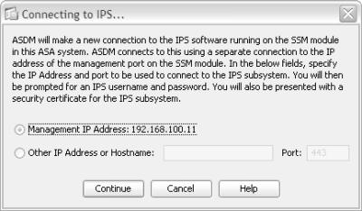
![]() To access the AIP from within ASDM, select the Configuration tab and the IPS link in the left-hand column, as shown in Figure 12-40.
To access the AIP from within ASDM, select the Configuration tab and the IPS link in the left-hand column, as shown in Figure 12-40.
| Tip |
|
 Updating the AIP License
![]() The AIP cannot inspect traffic at all until it has a valid license. In addition, you will not be able to access new IPS signature databases or upload them to the AIP without an active license and Cisco support contract.
The AIP cannot inspect traffic at all until it has a valid license. In addition, you will not be able to access new IPS signature databases or upload them to the AIP without an active license and Cisco support contract.
![]() If you purchased a license and support contract, you can enter the license key in one of two ways:
If you purchased a license and support contract, you can enter the license key in one of two ways:
-
 Directly from Cisco Connection Online (CCO, Cisco.com) or from ASDM/IDM
 -
 Upload from the ASDM or IDM client
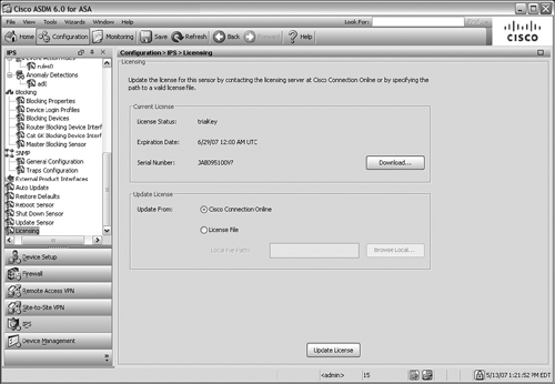
![]() In ASDM, select the Configuration tab and then click on the IPS button in the left-hand column. You should see a window similar to that displayed in Figure 12-41.
In ASDM, select the Configuration tab and then click on the IPS button in the left-hand column. You should see a window similar to that displayed in Figure 12-41.
![]() If you select the Update from Cisco Connection Online option, the AIP opens a connection to Cisco.com directly. It attempts to request and download a license automatically. If it is not successful, it gives you the option to request a 30-day trial license key.
If you select the Update from Cisco Connection Online option, the AIP opens a connection to Cisco.com directly. It attempts to request and download a license automatically. If it is not successful, it gives you the option to request a 30-day trial license key.
![]() If you received a license from Cisco in an e-mail, you can save the license as a file and upload it to the AIP. Select the Update from License File option and then click on the Browse Local button to locate the file. Finally, click on the Update License button to upload and install the license file.
If you received a license from Cisco in an e-mail, you can save the license as a file and upload it to the AIP. Select the Update from License File option and then click on the Browse Local button to locate the file. Finally, click on the Update License button to upload and install the license file.
 Manually Updating the AIP Code or Signature Files
![]() Occasionally, you might need to update the IPS code image or the signature database file on the AIP module. You can do this manually through the ASDM or IDM interface.
Occasionally, you might need to update the IPS code image or the signature database file on the AIP module. You can do this manually through the ASDM or IDM interface.
![]() First, download the new file from Cisco.com and save it on a local server. The AIP can retrieve an image file from an FTP, HTTP, HTTPS, or Secure Copy (SCP) server. You can also download the file and save it locally on the ASDM client machine.
First, download the new file from Cisco.com and save it on a local server. The AIP can retrieve an image file from an FTP, HTTP, HTTPS, or Secure Copy (SCP) server. You can also download the file and save it locally on the ASDM client machine.
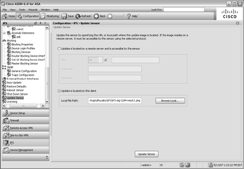
![]() From ASDM, select the Configuration tab and then IPS in the left-hand column. In the IPS task list, select Update Sensor, as shown in Figure 12-42.
From ASDM, select the Configuration tab and then IPS in the left-hand column. In the IPS task list, select Update Sensor, as shown in Figure 12-42.
![]() You can select Update is located on a remote server and is accessible by the sensor and supply the server type and URL, as well as a username and password. If you stored the image file on the local ASDM client machine, select Update is located on this client and click on the Browse Local button to locate the file.
You can select Update is located on a remote server and is accessible by the sensor and supply the server type and URL, as well as a username and password. If you stored the image file on the local ASDM client machine, select Update is located on this client and click on the Browse Local button to locate the file.
![]() Finally, click on the Update Sensor button to download the file to the AIP. If you updated the AIP image file, you also have to reboot the AIP to begin using the new code image. Signature database files, on the other hand, can be uploaded and used immediately without rebooting.
Finally, click on the Update Sensor button to download the file to the AIP. If you updated the AIP image file, you also have to reboot the AIP to begin using the new code image. Signature database files, on the other hand, can be uploaded and used immediately without rebooting.
 Automatically Updating AIP Image and Signature Files
![]() Manually updating files on one AIP can be somewhat tedious, but updating files on many AIP modules can get out of hand. You can make use of the Auto Update feature to configure one or more AIPs to leverage a more automatic process. An AIP can poll an FTP or SCP server at regular intervals to see if new files are available. If so, the AIP downloads the new files and begins using them.
Manually updating files on one AIP can be somewhat tedious, but updating files on many AIP modules can get out of hand. You can make use of the Auto Update feature to configure one or more AIPs to leverage a more automatic process. An AIP can poll an FTP or SCP server at regular intervals to see if new files are available. If so, the AIP downloads the new files and begins using them.
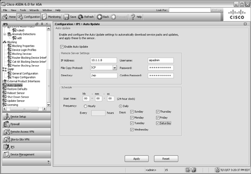
![]() In ASDM, select the Configure tab and then IPS, followed by the Auto Update link in the scrolling list. You should see a window like that in Figure 12-43.
In ASDM, select the Configure tab and then IPS, followed by the Auto Update link in the scrolling list. You should see a window like that in Figure 12-43.
![]() First, configure the AIP to begin polling the Auto Update Server (AUS) for new files. Click on the Enable Auto Update checkbox and then enter the IP address of the AUS machine, along with a valid username and password. Select the protocol to use for file copying (SCP or FTP) and the directory where the AIP files can be found.
First, configure the AIP to begin polling the Auto Update Server (AUS) for new files. Click on the Enable Auto Update checkbox and then enter the IP address of the AUS machine, along with a valid username and password. Select the protocol to use for file copying (SCP or FTP) and the directory where the AIP files can be found.
![]() Finally, enter the polling schedule that the AIP should use. Cisco can sometimes publish new IPS signature database files at least once a day, so you should consider selecting each day of the week for Auto Update. After you have entered all of the fields, click on the Apply button.
Finally, enter the polling schedule that the AIP should use. Cisco can sometimes publish new IPS signature database files at least once a day, so you should consider selecting each day of the week for Auto Update. After you have entered all of the fields, click on the Apply button.
| Tip |
|
 IPS Policies
![]() An IPS sensor like the AIP performs all of its inspections and analysis based on a set of policies. The policies are built on three components:
An IPS sensor like the AIP performs all of its inspections and analysis based on a set of policies. The policies are built on three components:
-
 IPS signatures— A database of predefined signatures or ways to describe suspicious activity; signatures are based on characteristics of the data being passed.
 -
 Event actions— The IPS sensor takes predefined actions on each signature that is detected in a traffic flow.
 -
 Anomaly detection— The IPS sensor can detect traffic anomalies or suspicious activity related to Internet worm propagation.
![]() By default, an AIP is preconfigured with a signature definition called sig0, a set of event action rules called rules0, and a set of anomaly detections called ad0. You can use the default policies or you can create your own through ASDM or IDM.
By default, an AIP is preconfigured with a signature definition called sig0, a set of event action rules called rules0, and a set of anomaly detections called ad0. You can use the default policies or you can create your own through ASDM or IDM.
Working with Signature Definitions
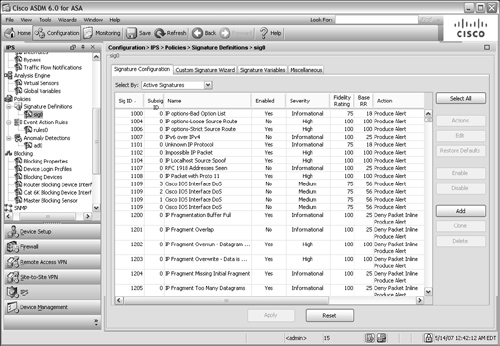
![]() From the ASDM, you can view the default signature definition sig0 by selecting the Configuration tab, then the IPS function, and then the Signature Definitions link under Policies in the scrolling list. Figure 12-44 shows a sample of sig0. Each signature has the following attributes:
From the ASDM, you can view the default signature definition sig0 by selecting the Configuration tab, then the IPS function, and then the Signature Definitions link under Policies in the scrolling list. Figure 12-44 shows a sample of sig0. Each signature has the following attributes:
-
 A unique signature ID— Each signature has a predefined identifier, shown in the Sig ID column
 -
 A descriptive name— A text string that describes the purpose of the signature
 -
 A severity factor— The severity factor is based on the following levels: Informational (25), Low (50), Medium (75), or High (100)
 -
 A fidelity rating— A weighting (1–100) of how well the signature might perform without any prior knowledge of the traffic target
 -
 A base RR— The base risk rating (1–100) or a composite index based on the severity level times the fidelity rating
 -
 An action— The action taken by the AIP when the signature fires
![]() You can use the default signature definition sig0 as-is, or you can make changes to individual signatures within sig0. Also, you can create your own customized signature definition based on sig0. To create a new definition, select Signature Definitions in the scrolling list and then select sig0 under Policy Name. You can click on the Clone button to make a copy of an existing signature definition or click on the Add button to create a new copy of sig0 with an arbitrary name.
You can use the default signature definition sig0 as-is, or you can make changes to individual signatures within sig0. Also, you can create your own customized signature definition based on sig0. To create a new definition, select Signature Definitions in the scrolling list and then select sig0 under Policy Name. You can click on the Clone button to make a copy of an existing signature definition or click on the Add button to create a new copy of sig0 with an arbitrary name.
Working with Event Action Rules
![]() Each signature used by the AIP has one or more specific actions defined. Whenever the signature fires or detects a specific behavior in the traffic, that action is taken. Basically, the actions are defined as one or more of the following:
Each signature used by the AIP has one or more specific actions defined. Whenever the signature fires or detects a specific behavior in the traffic, that action is taken. Basically, the actions are defined as one or more of the following:
-
 Deny some activity
 -
 Generate a log
 -
 Generate an alert
 -
 Request a reaction from a network device
 -
 Reset the connection
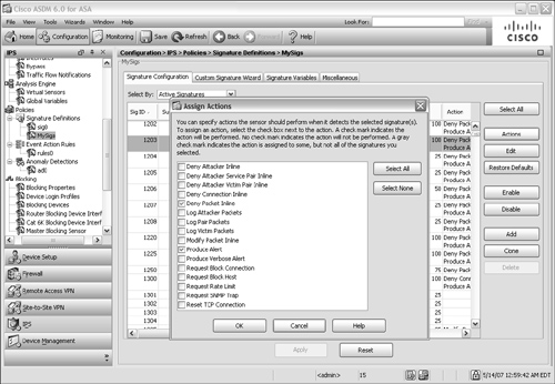
![]() Figure 12-45 shows the full set of actions that can be selected on a signature in the signature definition. The actions are predefined for each signature in the default sig0 definition, but can be overridden by configuring the signature.
Figure 12-45 shows the full set of actions that can be selected on a signature in the signature definition. The actions are predefined for each signature in the default sig0 definition, but can be overridden by configuring the signature.
![]() The AIP has a default set of event action rules called rules0 that can be used to override or set general parameters for actions. You can edit rules0 or define your own event action rule set by selecting the Configuration tab, then the IPS link, and then the Event Action Rules link in the scrolling list under Policies.
The AIP has a default set of event action rules called rules0 that can be used to override or set general parameters for actions. You can edit rules0 or define your own event action rule set by selecting the Configuration tab, then the IPS link, and then the Event Action Rules link in the scrolling list under Policies.
Working with Anomaly Detection Policies
![]() Beginning with IPS 6.0 (and ASA release 8.0), an AIP has an anomaly detection engine that can detect worm-based activity on a network. A worm is an agent that begins on one host and propagates to as many other hosts as possible. Worms spread themselves automatically by looking for other potential vulnerable targets through network scans.
Beginning with IPS 6.0 (and ASA release 8.0), an AIP has an anomaly detection engine that can detect worm-based activity on a network. A worm is an agent that begins on one host and propagates to as many other hosts as possible. Worms spread themselves automatically by looking for other potential vulnerable targets through network scans.
![]() Anomaly Detection (AD) works by detecting large amounts of scanning traffic from single hosts to many others. AD looks for unidirectional User Datagram Protocol (UDP) traffic, where the worm-infected host is sending packets to many destination addresses using the same destination port, with little return traffic. With TCP, AD looks for many half-open or embryonic connections from one host to many others, using the same destination port.
Anomaly Detection (AD) works by detecting large amounts of scanning traffic from single hosts to many others. AD looks for unidirectional User Datagram Protocol (UDP) traffic, where the worm-infected host is sending packets to many destination addresses using the same destination port, with little return traffic. With TCP, AD looks for many half-open or embryonic connections from one host to many others, using the same destination port.
![]() The AD feature can operate in the following modes:
The AD feature can operate in the following modes:
-
 Inactive mode— AD is disabled; anomalies or worm activities are not detected.
 -
 Learn mode— AD listens to the network traffic, gathering a baseline of typical activity. This baseline is known as the knowledge base.
 -
 Detect mode— The knowledge base is used as a threshold for worm-based activity. When the IPS sensor detects activity above the threshold, it sends alerts and takes action on the traffic. Detect mode also updates the knowledge base periodically, so it always has a current baseline of network traffic.
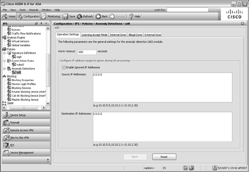
![]() The AIP has a default set of anomaly detection policies called ad0. You can edit the defaults or add your own set of AD policies by selecting the Configuration tab, then IPS, and then Anomaly Detections in the scrolling list under Policies as shown in Figure 12-46.
The AIP has a default set of anomaly detection policies called ad0. You can edit the defaults or add your own set of AD policies by selecting the Configuration tab, then IPS, and then Anomaly Detections in the scrolling list under Policies as shown in Figure 12-46.
![]() By default, the AIP runs AD in the detect mode, actively detecting and mitigating worm activity. When AD is first enabled on an IPS sensor, it runs for the first 24 hours in learn mode. After it gathers a baseline, it automatically moves to detect mode.
By default, the AIP runs AD in the detect mode, actively detecting and mitigating worm activity. When AD is first enabled on an IPS sensor, it runs for the first 24 hours in learn mode. After it gathers a baseline, it automatically moves to detect mode.
 AIP Interfaces
![]() The ASA and AIP are connected over the ASA chassis backplane by two hidden interfaces:
The ASA and AIP are connected over the ASA chassis backplane by two hidden interfaces:
-
 GigabitEthernet0/0— Used only for command and control traffic between the ASA and AIP.
 -
 GigabitEthernet0/1— Used for data transfer between the ASA and AIP; this is the only interface that can be monitored as a sensing interface by the AIP for IPS functions.
![]() From the ASA, neither of these interfaces is available or configurable. The interfaces can be seen and used only from the AIP itself.
From the ASA, neither of these interfaces is available or configurable. The interfaces can be seen and used only from the AIP itself.
![]() To perform IPS functions, an IPS platform must be able to monitor one or more of its interfaces. IPS sensor interfaces can be configured in any of the following ways:
To perform IPS functions, an IPS platform must be able to monitor one or more of its interfaces. IPS sensor interfaces can be configured in any of the following ways:
-
 Promiscuous monitoring— A single interface is used to monitor traffic; the IPS sensor can make decisions on what to do with the packets, but the packets do not actually pass through the IPS.
 -
 Inline interface— Usually two physical interfaces are configured as an inline pair, where the IPS sensor monitors traffic entering on one interface and exiting on the other.
 An AIP does not have multiple physical interfaces, so you can configure only a single interface in inline mode. Packets received from the ASA on the interface are examined by the AIP. If the AIP decides to permit a packet, the packet is returned to the ASA on the same interface for forwarding. If the AIP decides to block the packet, the packet is simply not returned to the ASA at all.
 -
 VLAN inline pair— Two VLAN interfaces are configured as an inline pair, so that the IPS sensor examines traffic entering on one VLAN interface and exiting on the other.
 The ASA platform cannot use VLAN inline interface pairs because only one interface (GigabitEthernet0/1) connects the ASA and AIP over the backplane.
 IPS Virtual Sensors
![]() IPS 6.0 enables an IPS platform, such as the AIP, to define virtual sensors that can monitor traffic in a variety of ways. ASA 8.0 (1) is the first release to offer virtual sensor support in cooperation with an AIP running IPS 6.0. With virtual sensors, a single IPS hardware platform can run multiple IPS sensors, all operating independently.
IPS 6.0 enables an IPS platform, such as the AIP, to define virtual sensors that can monitor traffic in a variety of ways. ASA 8.0 (1) is the first release to offer virtual sensor support in cooperation with an AIP running IPS 6.0. With virtual sensors, a single IPS hardware platform can run multiple IPS sensors, all operating independently.
![]() An AIP can operate up to four different virtual sensors. Each of the virtual sensors must use the only interface available on the AIP—GigabitEthernet0/1. Reusing the same interface might seem to be a severe limitation. However, the AIP is able to isolate traffic to and from the virtual sensors even over the same interface.
An AIP can operate up to four different virtual sensors. Each of the virtual sensors must use the only interface available on the AIP—GigabitEthernet0/1. Reusing the same interface might seem to be a severe limitation. However, the AIP is able to isolate traffic to and from the virtual sensors even over the same interface.
![]() Virtual sensors can be used in different policies within a policy map, and they can be allocated to one or more security contexts on an ASA. For example, you might customize one virtual sensor to meet the policies of a business unit and apply it to one security context. You could customize a different virtual sensor for another business unit, to be applied to a different context, and so on.
Virtual sensors can be used in different policies within a policy map, and they can be allocated to one or more security contexts on an ASA. For example, you might customize one virtual sensor to meet the policies of a business unit and apply it to one security context. You could customize a different virtual sensor for another business unit, to be applied to a different context, and so on.
![]() Each ASA context connects to the AIP over a different instance of backplane interface GigabitEthernet0/1. Remember that the virtual sensors are configured only on the AIP, so GigabitEthernet0/1 can be seen and manipulated only from the AIP—not from the ASA.
Each ASA context connects to the AIP over a different instance of backplane interface GigabitEthernet0/1. Remember that the virtual sensors are configured only on the AIP, so GigabitEthernet0/1 can be seen and manipulated only from the AIP—not from the ASA.
![]() You can configure virtual sensors on the AIP with the following steps:
You can configure virtual sensors on the AIP with the following steps:
-
 Configure IPS policies.
 The AIP is preconfigured with the default sig0 signature definition, rules0 event action rule set, and ad0 anomaly detection policies. You can use these policies as-is, or you can make changes to them as described in the section “IPS Policies” earlier in this chapter.
 The policies are applied to a sensor interface in Step 2.
 -
 Configure a virtual sensor.
 By default, one virtual sensor is preconfigured on an AIP. The virtual sensor is called vs0 and uses the GigabitEthernet0/1 backplane AIP interface. It also has the default policies sig0, rules0, and ad0 applied to it, as shown in Figure 12-47. Notice that the backplane interface is available to the virtual sensor, but has not been assigned to the sensor yet. This is done in Step 3.
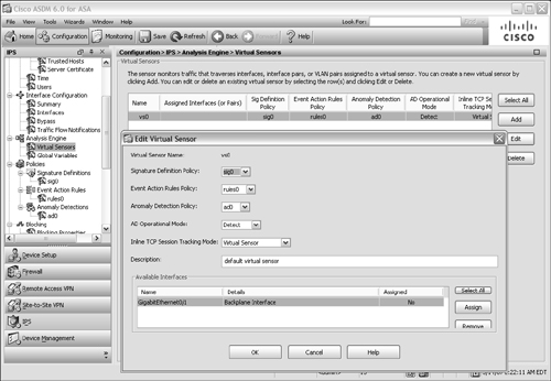
 Figure 12-47: The Default vs0 Virtual Sensor
  If your ASA is running in single-context security mode, you can use the default vs0 virtual sensor as it is already configured.
 If your ASA is running multiple context mode and has more than one security context configured, you can use vs0 as well as any new virtual sensor that you configure in any of the contexts.
 To configure a new virtual sensor, select the Configuration tab, then IPS, and then the Virtual Sensors link in the scrolling list under Analysis Engine. Click on the Add button and choose a name and policies for the sensor.
 -
 Assign an AIP interface to the virtual sensor.
 Before a virtual sensor can be used, you need to assign an AIP interface to it. Even the default vs0 virtual sensor does not have an interface assigned until you manually configure it.
 Select the Virtual Sensors link in the scrolling list under Analysis Engine and then select a virtual sensor. Next, click on the Edit button.
 The Edit Virtual Sensor window is shown. Toward the bottom of the window, GigabitEthernet0/1 is shown as an available interface, but shown as No in the Assigned column. To assign the interface, click on the Assign button. (If you ever need to unassign an interface from a virtual sensor, click on the Remove button.)
 In Figure 12-48, the default vs0 virtual sensor is being edited so that the GigabitEthernet0/1 interface can be assigned to it.
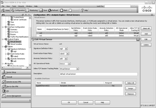
 Figure 12-48: Assigning a Sensing Interface to a Virtual Sensor
  On an AIP, every virtual sensor is assigned to the GigabitEthernet0/1 backplane interface. Actually, the interface must be explicitly assigned to one virtual sensor; after that is done, it is implicitly assigned to the other virtual sensors.
 Do not worry about duplicating the interface across the sensors—the ASA and AIP take care of keeping the sensors isolated to their security contexts.
 -
 Apply the virtual sensor to an ASA context.
 If the ASA is running in multiple context mode, the virtual sensor must be mapped to a security context. Use the following command in context configuration mode:
 Firewall(config-ctx)# allocate-ips sensor_name [mapped_name] [default]
 The virtual sensor named sensor_name is applied to the current context. By default, the sensor name also appears in the context configuration. If you do not want a context administrator to see the actual name of the sensor, you can supply an alias as mapped_name to be seen.
 As an example, suppose virtual sensors vs0 and vs1 have been configured on the AIP and are to be applied to security contexts Department1 and Department2, respectively. You can use the following commands to apply the virtual sensors:
 Firewall(config)# context Department1
Firewall(config-ctx)# allocate-interface Ethernet0/0
Firewall(config-ctx)# allocate-interface Ethernet0/1
Firewall(config-ctx)# allocate-ips vs0 ips-a
Firewall(config-ctx)# config-url disk0:/dept1.cfg
Firewall(config-ctx)# exit
Firewall(config)# context Department2
Firewall(config-ctx)# allocate-interface Ethernet0/2
Firewall(config-ctx)# allocate-interface Ethernet0/3
Firewall(config-ctx)# allocate-ips vs1 ips-b
Firewall(config-ctx)# config-url disk0:/dept2.cfg
Firewall(config-ctx)# exit Notice that the virtual sensors are configured with mapped names ips-a and ips-b. In the contexts, the administrators see only the mapped names:
 Firewall/Department1# show ips
Sensor Name
-----------
ips-a
Firewall/Department1# Also, you can allocate multiple virtual sensors across the contexts in any fashion, as in the following example:
 Firewall(config)# context Department1
Firewall(config-ctx)# allocate-interface Ethernet0/0
Firewall(config-ctx)# allocate-interface Ethernet0/1
Firewall(config-ctx)# allocate-ips vs0 ips-a
Firewall(config-ctx)# allocate-ips vs1 ips-b
Firewall(config-ctx)# config-url disk0:/dept1.cfg
Firewall(config-ctx)# exit
Firewall(config)# context Department2
Firewall(config-ctx)# allocate-interface Ethernet0/2
Firewall(config-ctx)# allocate-interface Ethernet0/3
Firewall(config-ctx)# allocate-ips vs1 ips-a
Firewall(config-ctx)# config-url disk0:/dept2.cfg
Firewall(config-ctx)# exit -
 Configure an ASA policy map to divert traffic to virtual sensor.
 By default, the ASA does not send any traffic to an IPS virtual sensor. You need to configure a policy map that matches traffic to be inspected and then apply the policy map in a service policy.
 In the policy map configuration, use the following command to divert traffic to the virtual sensor:
 Firewall(config)# policy-map pmap_name
Firewall(config-pmap)# class cmap_name
Firewall(config-pmap-c)# ips {promiscuous | inline} {fail-close | fail-open} [sensor
sensor_name]
Firewall(config-pmap-c)# exit
Firewall(config-pmap)# exit The virtual sensor can be used in promiscuous or inline mode. In addition, you can configure the ASA to keep forwarding traffic normally (fail-open) or to block all traffic (fail-close) if the AIP fails.
 You can give the virtual sensor name with the sensor keyword, as either the virtual sensor name or the mapped name used in the context. If you do not give the sensor keyword, the default sensor is used.
 In the following example, all traffic passing through the ASA’s outside interface is diverted to virtual sensor vs0.
 Firewall(config)# class-map anything
Firewall(config-cmap)# match any
Firewall(config-cmap)# exit
!
Firewall(config)# policy-map MyPolicy
Firewall(config-pmap)# class anything
Firewall(config-pmap-c)# ips inline fail-close sensor vs0
Firewall(config-pmap-c)# exit
Firewall(config-pmap)# exit
Firewall(config)# service-policy MyPolicy interface outside If you have configured more than one virtual sensor on the AIP, you can divert different traffic to each by referencing them with multiple ips commands in the policy map.

2 comments
You have share a terribly inestimable and focused on information, I consider it should help researchers who need to move their checks...Cooking Madness
as he would because of the way that he didn't appreciate when he would see him once more. The young man was once also restless in view that he knew nothing of London or of england.
information and news
Post a Comment