
Troubleshooting Branch Office and Remote Worker Connectivity
![]() This section discusses issues related to remote-access connectivity both for branch offices and for remote workers. The focus of the discussion remains on the impact of the overall solution in routing and switching and on the underlying requirements to support branch and remote worker connectivity.
This section discusses issues related to remote-access connectivity both for branch offices and for remote workers. The focus of the discussion remains on the impact of the overall solution in routing and switching and on the underlying requirements to support branch and remote worker connectivity.
 Branch Office and Remote Worker Connectivity
![]() Branch office connectivity involves multiple topics and technologies, including WAN connectivity through VPN and generic routing encapsulation (GRE) tunnels, routing, LAN services, security, and other topics (see Figure 9-4).
Branch office connectivity involves multiple topics and technologies, including WAN connectivity through VPN and generic routing encapsulation (GRE) tunnels, routing, LAN services, security, and other topics (see Figure 9-4).
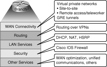
![]() VPN connectivity is a major method used for modern branch office and remote-access connectivity. In many cases routing protocols are run over the VPN connection. VPN connectivity is often used as a WAN backup solution. Support services, such as Dynamic Host Configuration Protocol (DHCP), Network Address Translation (NAT), and Hot Standby Router Protocol (HSRP), provide the necessary infrastructure for VPN traffic to be successfully routed end to end. Security is an important part of remote connectivity. Cisco IOS firewalls and other security controls are becoming increasingly popular in branch deployments. That is also true for advanced services such as Cisco Unified Communications and WAN optimization. The end result is a series of functions that are not only integrated in your router devices, but also have a clear impact in, and are affected by, routing.
VPN connectivity is a major method used for modern branch office and remote-access connectivity. In many cases routing protocols are run over the VPN connection. VPN connectivity is often used as a WAN backup solution. Support services, such as Dynamic Host Configuration Protocol (DHCP), Network Address Translation (NAT), and Hot Standby Router Protocol (HSRP), provide the necessary infrastructure for VPN traffic to be successfully routed end to end. Security is an important part of remote connectivity. Cisco IOS firewalls and other security controls are becoming increasingly popular in branch deployments. That is also true for advanced services such as Cisco Unified Communications and WAN optimization. The end result is a series of functions that are not only integrated in your router devices, but also have a clear impact in, and are affected by, routing.
Identifying Issues with Branch Office and Remote Worker Connectivity
![]() With respect to VPN connectivity, configuration errors are the typical cause of parameter mismatches on the VPN-termination routers. In the case of GRE tunnels, for example, misconfiguring tunnel source and tunnel destination causes routing issues that prevent the tunnel from forming and becoming active. In many situations, it is not even the VPN that is the cause of the problem. An example is the case of overlapping IP subnets on the opposite sides of the tunnel: NAT is needed to artificially make the subnets nonoverlapping. For remote-access VPNs, given that connections are typically initiated from a remote host, usually a PC or laptop, potential issues relate to host readiness. For example, endpoint security such as antivirus software filters essential traffic and prevents connectivity. User authentication and authorization is also a critical function; if users are not recognized or their permissions are not properly set, they will not be able to connect as teleworkers.
With respect to VPN connectivity, configuration errors are the typical cause of parameter mismatches on the VPN-termination routers. In the case of GRE tunnels, for example, misconfiguring tunnel source and tunnel destination causes routing issues that prevent the tunnel from forming and becoming active. In many situations, it is not even the VPN that is the cause of the problem. An example is the case of overlapping IP subnets on the opposite sides of the tunnel: NAT is needed to artificially make the subnets nonoverlapping. For remote-access VPNs, given that connections are typically initiated from a remote host, usually a PC or laptop, potential issues relate to host readiness. For example, endpoint security such as antivirus software filters essential traffic and prevents connectivity. User authentication and authorization is also a critical function; if users are not recognized or their permissions are not properly set, they will not be able to connect as teleworkers.
![]() GRE tunnels deserve special consideration because they are typically used to transport routing protocols across IPsec VPNs. A common issue is related to maximum transmission unit (MTU) and fragmentation. Routing protocol packets are first encapsulated in GRE packets. It is those GRE packets that in turn get encapsulated within IPsec tunnel packets. The remote end needs to do two decapsulations when terminating the tunnel. This architecture can cause many performance issues such as extra work at the router level because of double encapsulation, packet sizes, MTU, and fragmentation. Problems related to GRE tunnel establishment are usually due to configurations of tunnel sources and tunnel destinations, along with improper routing of loopbacks. Network readiness is also important because firewalls and traffic filters may block the IPsec traffic that carries the GRE tunnels. Multiple GRE point-to-point tunnels can saturate the physical link with routing information if the bandwidth is not adequately provisioned or configured on the tunnel interface.
GRE tunnels deserve special consideration because they are typically used to transport routing protocols across IPsec VPNs. A common issue is related to maximum transmission unit (MTU) and fragmentation. Routing protocol packets are first encapsulated in GRE packets. It is those GRE packets that in turn get encapsulated within IPsec tunnel packets. The remote end needs to do two decapsulations when terminating the tunnel. This architecture can cause many performance issues such as extra work at the router level because of double encapsulation, packet sizes, MTU, and fragmentation. Problems related to GRE tunnel establishment are usually due to configurations of tunnel sources and tunnel destinations, along with improper routing of loopbacks. Network readiness is also important because firewalls and traffic filters may block the IPsec traffic that carries the GRE tunnels. Multiple GRE point-to-point tunnels can saturate the physical link with routing information if the bandwidth is not adequately provisioned or configured on the tunnel interface.
![]() The point-to-point nature of GRE tunnels, along with the hub-and-spoke nature of the typical GRE solution, might represent an issue, in terms of round-trip delay for latency-sensitive traffic in spoke-to-spoke connectivity. The point-to-point nature of traditional GRE tunnels makes a full-mesh solution a challenge, in terms of the burden that all routers have to terminate a high number of tunnels. This is the motivation behind introduction of technologies that alleviate the full-mesh requirement, making it dynamic, automatic, and efficient. Examples of such technologies are Virtual Tunnel Interface (VTI), Dynamic Multipoint VPN (DMVPN), and Group-Encrypted Transport VPN (GET VPN).
The point-to-point nature of GRE tunnels, along with the hub-and-spoke nature of the typical GRE solution, might represent an issue, in terms of round-trip delay for latency-sensitive traffic in spoke-to-spoke connectivity. The point-to-point nature of traditional GRE tunnels makes a full-mesh solution a challenge, in terms of the burden that all routers have to terminate a high number of tunnels. This is the motivation behind introduction of technologies that alleviate the full-mesh requirement, making it dynamic, automatic, and efficient. Examples of such technologies are Virtual Tunnel Interface (VTI), Dynamic Multipoint VPN (DMVPN), and Group-Encrypted Transport VPN (GET VPN).
![]() Misconfiguration of routing over GRE tunnels can lead to recursive routing. When the best path to the tunnel destination is through the tunnel itself, recursive routing causes the tunnel interface to flap. The tunnel interface status depends on IP reachability to the tunnel destination. When the router detects a recursive routing failure for the tunnel destination, it shuts the tunnel interface down for a few minutes so that the situation causing the problem can resolve itself as the routing protocol converges. If the problem is caused by misconfiguration, the link might flap indefinitely. In normal situations, this might occur by just enabling a routing protocol such as Enhanced Interior Gateway Routing Protocol (EIGRP) over the tunnel. In the example shown in Figure 9-5, the GRE tunnel is terminated at the loopback interfaces of the routers at each end. Those loopback interfaces are also injected into EIGRP, and they are advertised across the tunnel to the other side, from R3 to R1 and vice versa. The routing tables will show that the best path to the loopbacks, the source of the tunnel, is the tunnel itself. This causes the inconsistent routing that leads to the recursive routing problem.
Misconfiguration of routing over GRE tunnels can lead to recursive routing. When the best path to the tunnel destination is through the tunnel itself, recursive routing causes the tunnel interface to flap. The tunnel interface status depends on IP reachability to the tunnel destination. When the router detects a recursive routing failure for the tunnel destination, it shuts the tunnel interface down for a few minutes so that the situation causing the problem can resolve itself as the routing protocol converges. If the problem is caused by misconfiguration, the link might flap indefinitely. In normal situations, this might occur by just enabling a routing protocol such as Enhanced Interior Gateway Routing Protocol (EIGRP) over the tunnel. In the example shown in Figure 9-5, the GRE tunnel is terminated at the loopback interfaces of the routers at each end. Those loopback interfaces are also injected into EIGRP, and they are advertised across the tunnel to the other side, from R3 to R1 and vice versa. The routing tables will show that the best path to the loopbacks, the source of the tunnel, is the tunnel itself. This causes the inconsistent routing that leads to the recursive routing problem.


![]() A number of other considerations with respect to troubleshooting branch connectivity relate to network readiness, including the following:
A number of other considerations with respect to troubleshooting branch connectivity relate to network readiness, including the following:
- Are there firewalls or access lists blocking the VPN traffic?
- Are there overlapping subnets at the opposite ends of the tunnel?
- Is asymmetric routing causing VPN tunnels to fail?
- Do we have HSRP aligned with VPN high-availability functions? (When an HSRP failover happens, does the new HSRP active router have or set up a VPN connection to the remote site so that the operations can carry on?)
![]() All these issues deal with the routing, addressing, and high-availability infrastructures present in the network. They are necessary for branch connectivity and require additional configuration, and therefore require additional troubleshooting when they fail.
All these issues deal with the routing, addressing, and high-availability infrastructures present in the network. They are necessary for branch connectivity and require additional configuration, and therefore require additional troubleshooting when they fail.
![]() Dealing with the issues such as those mentioned, a structured troubleshooting approach is necessary, in conjunction with knowledge of the building block technologies. For example, gathering information on symptoms and existing configurations requires a multidimensional approach: The IP addressing scheme at the branch office and the central location must be determined, the type of VPN must be recognized, the networks to be advertised by the routing protocol must be known, and the MTU values (per interface and path-long maximum) must be identified. These questions touch many areas and building-block technologies. Similarly, our analysis needs to have an integrated approach, and the same multidimensional, integrated approach is needed when suggesting hypotheses for the problem.
Dealing with the issues such as those mentioned, a structured troubleshooting approach is necessary, in conjunction with knowledge of the building block technologies. For example, gathering information on symptoms and existing configurations requires a multidimensional approach: The IP addressing scheme at the branch office and the central location must be determined, the type of VPN must be recognized, the networks to be advertised by the routing protocol must be known, and the MTU values (per interface and path-long maximum) must be identified. These questions touch many areas and building-block technologies. Similarly, our analysis needs to have an integrated approach, and the same multidimensional, integrated approach is needed when suggesting hypotheses for the problem.
![]() Because branch connectivity touches so many areas, your tool box for troubleshooting its deployments include show and debug commands in many areas. On the one hand, you need some basic knowledge of IPsec troubleshooting. On the other hand, you need some GRE troubleshooting tools.
Because branch connectivity touches so many areas, your tool box for troubleshooting its deployments include show and debug commands in many areas. On the one hand, you need some basic knowledge of IPsec troubleshooting. On the other hand, you need some GRE troubleshooting tools.
![]() Table 9-1 lists a simple set of show and debug commands that examine and display the status of VPN and GRE tunnels, IP routing table and protocols, and some IP services such as DHCP, NAT, and HSRP.
Table 9-1 lists a simple set of show and debug commands that examine and display the status of VPN and GRE tunnels, IP routing table and protocols, and some IP services such as DHCP, NAT, and HSRP.
|
|
|
|---|---|
|
|
|
|
|
|
|
|
|
|
|
|
Branch Office/Remote Worker Troubleshooting Example: Address Translation Error
![]() The troubleshooting examples presented in this section are all based on the network topology diagram shown in Figure 9-6, with changes to accommodate for different scenarios. Any changes to addressing or routing will be noted appropriately. The diagram shows a private WAN and an Internet option for branch connectivity. There is also a remote-access service for mobile users and traveling users.
The troubleshooting examples presented in this section are all based on the network topology diagram shown in Figure 9-6, with changes to accommodate for different scenarios. Any changes to addressing or routing will be noted appropriately. The diagram shows a private WAN and an Internet option for branch connectivity. There is also a remote-access service for mobile users and traveling users.


![]() The first troubleshooting example is a common case. The Branch router is using an IPsec tunnel to provide connectivity to headquarters for its LAN users. This deployment has been working for a while, but a recent change in NAT configuration has caused the tunnel to go down and to not get reestablished, and VPN connectivity to fail. Regular Internet access, however, has been restored, and users are able to connect to websites normally. Figure 9-7 shows the diagram specific to this case.
The first troubleshooting example is a common case. The Branch router is using an IPsec tunnel to provide connectivity to headquarters for its LAN users. This deployment has been working for a while, but a recent change in NAT configuration has caused the tunnel to go down and to not get reestablished, and VPN connectivity to fail. Regular Internet access, however, has been restored, and users are able to connect to websites normally. Figure 9-7 shows the diagram specific to this case.


![]() The first step in a structured approach is to gather information. A good initial question to ask is how many branches are experiencing the same problem. If all branches are experiencing the same problem, the central hub router is the best candidate to be analyzed first. In this example, the trouble report clearly states that this is the only branch experiencing the problem. Given that NAT was recently changed, you can try a “shoot-from-the-hip” approach. This means that you will use your experience and try to solve the problem quickly by considering alternatives that are apparent: It seems reasonable to look at the NAT changes and start from there. On the Branch router, you use the show ip nat statistics command to display NAT information (see Example 9-13).
The first step in a structured approach is to gather information. A good initial question to ask is how many branches are experiencing the same problem. If all branches are experiencing the same problem, the central hub router is the best candidate to be analyzed first. In this example, the trouble report clearly states that this is the only branch experiencing the problem. Given that NAT was recently changed, you can try a “shoot-from-the-hip” approach. This means that you will use your experience and try to solve the problem quickly by considering alternatives that are apparent: It seems reasonable to look at the NAT changes and start from there. On the Branch router, you use the show ip nat statistics command to display NAT information (see Example 9-13).
Total active translations: 1 (1 static, 0 dynamic, 0 extended)
Outside interfaces:
Serial0/0/0
Inside interfaces:
FastEthernet0/0
Hits: 0 Misses: 0
CEF Translated packets: 0, CEF Punted packets: 0
Expired translations: 0
Dynamic mappings:
–– Inside Source
[Id: 1] access-list 150 pool PUBLIC refcount 0
pool PUBLIC: netmask 255.255.255.0
start 172.16.1.100 end 172.16.1.200
type generic, total addresses 101, allocated 0 (0%), misses 0
[Id: 2] access-list VPN pool VPN_NAT refcount 0
start 10.1.10.10 end 10.1.10.200
type generic, total addresses 191, allocated 0 (0%), misses 0
Queued Packets: 0
BRANCH#
![]() From the output in Example 9-13, you can see that the VPN traffic is exempted from “public” translation because it remains private as it goes through the tunnel. Based on the network topology diagram, there is a culprit, however: The subnets on the opposite sides of the VPN are both using address 10.1.1.0/24 (overlapping)! Because of this overlap, NAT is needed to translate VPN traffic into something other than 10.1.1.0/24 on both sides. According to the output of the valuable show ip nat statistics command, traffic matching the VPN access list is being statically translated into an address from the range 10.1.10.10 to 10.1.10.200. This does not seem correct. Based on the information on the diagram (Figure 9-7), traffic leaving the branch toward the headquarters (destination subnet 10.1.4.0/24), should have its source address translate to an address from the 10.1.3.0/24 subnet. The traffic leaving the headquarters network should have its source address translated to an address from the 10.1.4.0/24 subnet.
From the output in Example 9-13, you can see that the VPN traffic is exempted from “public” translation because it remains private as it goes through the tunnel. Based on the network topology diagram, there is a culprit, however: The subnets on the opposite sides of the VPN are both using address 10.1.1.0/24 (overlapping)! Because of this overlap, NAT is needed to translate VPN traffic into something other than 10.1.1.0/24 on both sides. According to the output of the valuable show ip nat statistics command, traffic matching the VPN access list is being statically translated into an address from the range 10.1.10.10 to 10.1.10.200. This does not seem correct. Based on the information on the diagram (Figure 9-7), traffic leaving the branch toward the headquarters (destination subnet 10.1.4.0/24), should have its source address translate to an address from the 10.1.3.0/24 subnet. The traffic leaving the headquarters network should have its source address translated to an address from the 10.1.4.0/24 subnet.
![]() It seems that the translation done for the VPN traffic at the branch office is incorrect. The branch traffic’s source address is being translated to 10.1.10.x rather than 10.1.3.x. At first glance, you might think that does not matter as long as the branch traffic’s source address translates into something other than 10.1.1.x. That is not true. The VPN traffic you are translating will eventually go to the WAN interface to be tunneled through the IPsec VPN. The translated address must match the crypto access list; otherwise, it will not go through the VPN tunnel. You can verify this information using the show crypto map command as demonstrated in Example 9-14. As mentioned previously, the crypto map contains a crypto ACL that defines the traffic that it will accept to the VPN tunnel.
It seems that the translation done for the VPN traffic at the branch office is incorrect. The branch traffic’s source address is being translated to 10.1.10.x rather than 10.1.3.x. At first glance, you might think that does not matter as long as the branch traffic’s source address translates into something other than 10.1.1.x. That is not true. The VPN traffic you are translating will eventually go to the WAN interface to be tunneled through the IPsec VPN. The translated address must match the crypto access list; otherwise, it will not go through the VPN tunnel. You can verify this information using the show crypto map command as demonstrated in Example 9-14. As mentioned previously, the crypto map contains a crypto ACL that defines the traffic that it will accept to the VPN tunnel.
Crypto Map "map1" 10 ipsec-isakmp
Peer = 192.168.1.2
Extended IP access list 106
access-list 106 permit ip 10.1.3.0 0.0.0.255 10.1.4.0 0.0.0.255
Current peer: 192.168.1.2
Security association lifetime: 4608000 kilobytes/3600 seconds
PFS (Y/N): N
Transform sets={
Ts1,
}
Interfaces using crypto map map1:
Serial0/0/0
![]() The output of the show crypto map shows that the access list used is ACL 106 and it only matches traffic with source address of 10.1.3.x and destination address of 10.1.4.x. Therefore, if the source address of the traffic from the branch translates to anything other than 10.1.3.x, it will not go through the VPN tunnel. You are now sure that the NAT configuration is inconsistent with the crypto map (VPN) configuration, and fixing that might solve our problem. You correct the VPN_NAT pool by removing the old definition and adding the new definition, as shown in Example 9-15. To test that the problem is solved, you ping an address from the 10.1.4.0 pool (headquarters) and notice that now the ping is successful and the issue is indeed taken care of.
The output of the show crypto map shows that the access list used is ACL 106 and it only matches traffic with source address of 10.1.3.x and destination address of 10.1.4.x. Therefore, if the source address of the traffic from the branch translates to anything other than 10.1.3.x, it will not go through the VPN tunnel. You are now sure that the NAT configuration is inconsistent with the crypto map (VPN) configuration, and fixing that might solve our problem. You correct the VPN_NAT pool by removing the old definition and adding the new definition, as shown in Example 9-15. To test that the problem is solved, you ping an address from the 10.1.4.0 pool (headquarters) and notice that now the ping is successful and the issue is indeed taken care of.
Enter configuration commands, one per line. End with CNTL/Z
BRANCH(config)# no ip nat pool VPN_NAT 10.1.10.10 10.1.10.200 netmask
255.255.255.0
BRANCH(config)#
BRANCH(config)# ip nat pool VPN_NAT 10.1.3.10 10.1.3.200 netmask 255.255.255.0
BRANCH(config)#
BRANCH(config)# end
BRANCH#
BRANCH#
%SYS-5-CONFIG_I: Configured from console by console
BRANCH#
BRANCH# ping 10.1.4.1 source f0/0
Type escape sequence to abort.
Sending 5, 100-byte ICMP Echos to 10.1.4.1, timeout is 2 seconds:
Packet sent with a source address of 10.1.1.1
!!!!!
Success rate is 100 percent (5/5), round-trip min/avg/max - 56/57/60 ms
BRANCH#
Branch Office/Remote Worker Troubleshooting Example: Crypto Map ACL Error
![]() The second troubleshooting example is based on the same topology as the first example (shown in Figure 9-8). However, this time there is no subnet overlapping between the branch and headquarters networks. The symptoms of this troubleshooting example are similar to the last one: The VPN connection is down, but the Internet connection is working well. This time, however, there have not been any recent documented configuration changes, and no other information is provided.
The second troubleshooting example is based on the same topology as the first example (shown in Figure 9-8). However, this time there is no subnet overlapping between the branch and headquarters networks. The symptoms of this troubleshooting example are similar to the last one: The VPN connection is down, but the Internet connection is working well. This time, however, there have not been any recent documented configuration changes, and no other information is provided.


![]() You need to keep in mind that you are troubleshooting end to end and that multiple components and technologies are involved. The culprit could be anything from incorrect DHCP pools to routing issues and VPN configurations. For this reason, a follow-the-path approach is more appropriate in this case. As you analyze each function along the path, you should be able to discard potential issues and eventually isolate the problem. Taking this approach requires that you understand the order of processing of the various functions within the router.
You need to keep in mind that you are troubleshooting end to end and that multiple components and technologies are involved. The culprit could be anything from incorrect DHCP pools to routing issues and VPN configurations. For this reason, a follow-the-path approach is more appropriate in this case. As you analyze each function along the path, you should be able to discard potential issues and eventually isolate the problem. Taking this approach requires that you understand the order of processing of the various functions within the router.
![]() This Branch router is providing DHCP services to LAN hosts, so you can start there and use a bottom-up approach for each phase or step along the path. First, using the show ip interfaces brief command, you check the Layer 1 and Layer 2 status of the Branch router’s interfaces. As shown in Example 9-16, both the LAN and WAN interfaces are up.
This Branch router is providing DHCP services to LAN hosts, so you can start there and use a bottom-up approach for each phase or step along the path. First, using the show ip interfaces brief command, you check the Layer 1 and Layer 2 status of the Branch router’s interfaces. As shown in Example 9-16, both the LAN and WAN interfaces are up.
Interface IP-Address OK? Method Status Protocol
FastEthernet0/0 10.1.1.1 YES manual up up
FastEthernet0/1 unassigned YES unset administratively down down
Serial0/0/0 172.16.1.1 YES manual up up
NVIO unassigned NO unset up up
BRANCH#
![]() Now you can check whether hosts are obtaining IP address and related parameters through DHCP. The show ip dhcp pool command on the Branch router confirms that the address space 10.1.1.0/24 is being served to hosts through DHCP (see Example 9-17).
Now you can check whether hosts are obtaining IP address and related parameters through DHCP. The show ip dhcp pool command on the Branch router confirms that the address space 10.1.1.0/24 is being served to hosts through DHCP (see Example 9-17).
Pool LAN :
Utilization mark (high/low) : 100 / 0
Subnet size (first/next) : 0 / 0
Total addresses : 254
Leased addresses : 6
Pending event : none
1 subnet is currently in the pool :
Current index IP address range Leased addresses
10.1.1.1 10.1.1.1 - 10.1.1.254 6
![]() Now you can check to see whether there is a routing problem. Using the show ip route command as demonstrated in Example 9-18, you see what is expected for a small branch office (a static default pointing to a next hop on the WAN interface).
Now you can check to see whether there is a routing problem. Using the show ip route command as demonstrated in Example 9-18, you see what is expected for a small branch office (a static default pointing to a next hop on the WAN interface).
Codes: C - connected, S - static, R - RIP, M - mobile, B - BGP
D - EIGRP, EX - EIGRP external, O - OSPF, IA - OSPF inter area
N1 - OSPF NSSA external tyupe 1, N2 - OSPF NSSA external type 2
E1 - OSPF external type 1, E2 - OSPF external type 2
I - IS-IS, SU - IS-IS summary, L1 - IS-IS level-1, L2 - IS-IS level-2
ia - IS-IS inter area, * - candidate default, U - per-user static route
o - ODR, P - periodic downloaded static route
Gateway of last resort is 172.16.1.2 to network 0.0.0.0
172.16.0.0 255.255.255.0 is subnetted, 1 subnets
C 172.16.1.0 is directly connected, Serial0/0/0
10.0.0.0 255.255.255.0 is subnetted, 3 subnets
C 10.1.1.0 is directly connected, FastEthernet0/0
S* 0.0.0.0 0.0.0.0 [1/0] via 172.16.1.2
BRANCH#
![]() Next, you should check NAT. A basic rule of VPN connectivity is that VPN traffic should not use NAT, except for the overlapping network scenario, which is not the case here, as demonstrated in Example 9-19 with the show ip nat statistics command. The output reveals that traffic matching ACL 107 will be translated. So, you display ACL 107 to see its content (also shown in Example 9-19). ACL 107 looks correct because it denies traffic going from branch to headquarters, and that means the traffic going from branch to headquarters will not be subjected to NAT.
Next, you should check NAT. A basic rule of VPN connectivity is that VPN traffic should not use NAT, except for the overlapping network scenario, which is not the case here, as demonstrated in Example 9-19 with the show ip nat statistics command. The output reveals that traffic matching ACL 107 will be translated. So, you display ACL 107 to see its content (also shown in Example 9-19). ACL 107 looks correct because it denies traffic going from branch to headquarters, and that means the traffic going from branch to headquarters will not be subjected to NAT.
Total active translations: 1 (1 static, 0 dynamic, 0 extended)
Outside interfaces:
Serial0/0/0
Inside interfaces:
FastEthernet0/0
Hits: 60 Misses: 0
CEF Translated packets: 10, CEF Punted packets: 30
Expired translations: 7
Dynamic mappings:
–– Inside Source
[Id: 3] access-list 107 pool PUBLIC refcount 0
pool PUBLIC: netmask 255.255.255.0
start 172.16.1.100 end 172.16.1.200
type generic, total addresses 101, allocated 0 (0%), misses 0
Queued Packets: 0
BRANCH#
BRANCH# show access-list 107
Extended IP access list 107
10 deny ip 10.1.1.0 0.0.0.255 10.2.2.0 0.0.0.255
20 permit ip 10.1.1.0 0.0.0.255 any
BRANCH#
![]() Next, check the VPN configuration using the show crypto map on the Branch router as demonstrated in Example 9-20. ACL 106 used in the crypto map states that only the traffic with source address 10.1.3.x and destination address 10.2.2.y will go through the VPN tunnel. That is incorrect, however, because the traffic from the branch going to the headquarters (which is not subject to NAT) will have source address of 10.1.1.x, which is furnished by the DHCP server.
Next, check the VPN configuration using the show crypto map on the Branch router as demonstrated in Example 9-20. ACL 106 used in the crypto map states that only the traffic with source address 10.1.3.x and destination address 10.2.2.y will go through the VPN tunnel. That is incorrect, however, because the traffic from the branch going to the headquarters (which is not subject to NAT) will have source address of 10.1.1.x, which is furnished by the DHCP server.
Crypto Map "map1" 10 ipsec-isakmp
Peer = 192.168.1.2
Extended IP access list 106
access-list 106 permit ip 10.1.3.0 0.0.0.255 10.2.2.0 0.0.0.255
Current peer: 192.168.1.2
Security association lifetime: 4608000 kilobytes/3600 seconds
PFS (Y/N): N
Transform sets={
ts1,
}
Interfaces using crypto map map1:
Serial0/0/0
BRANCH#
![]() It seems that you have found the problem cause: The source IP addresses of the packets from the branch office are not matching the crypto ACL. You can test this hypothesis just by changing the crypto ACL 106 and using the ping command to verify connectivity, as demonstrated in Example 9-21. The ping from branch to the headquarters is successful, and the problem is fixed.
It seems that you have found the problem cause: The source IP addresses of the packets from the branch office are not matching the crypto ACL. You can test this hypothesis just by changing the crypto ACL 106 and using the ping command to verify connectivity, as demonstrated in Example 9-21. The ping from branch to the headquarters is successful, and the problem is fixed.
Enter configuration commands, one per line. End with CNTL/Z
BRANCH(config)# no access-list 106
BRANCH(config)#
BRANCH(config)# access-list 106 permit ip 10.1.1.0 0.0.0.255 10.2.2.0 0.0.0.255
BRANCH(config)#
BRANCH(config)# end
BRANCH#
%SYS-5-CONFIG_I: Configured from console by console
BRANCH#
BRANCH# ping 10.2.2.1 source f0/0
Type escape sequence to abort.
Sending 5, 100-byte ICMP Echos to 10.2.2.1, timeout is 2 seconds:
Packet sent with a source address of 10.1.1.1
!!!!!
Success rate is 100 percent (5/5), round-trip min/avg/max - 88/89/92 ms
BRANCH#
Branch Office/Remote Worker Troubleshooting Example: GRE Configuration Error
![]() The third troubleshooting example is based on the network topology shown in Figure 9-9. In this example, you are routing EIGRP across an IPsec VPN tunnel, using GRE. The GRE tunnel is sourced at the loopback interfaces on each router: 10.100.100.1 on the Branch router, and 10.200.200.2 on the Headquarters router. EIGRP is used to advertise internal networks, the networks on the 10.0.0.0 address space, for branch-to-headquarters connectivity. This time the problem is that traffic is not reaching the headquarters network, which hosts multiple mission-critical servers. At this point, the support team does not have many details, just that connectivity is lost. In dealing with this type of issue, it is best to apply a structured, follow-the-path approach.
The third troubleshooting example is based on the network topology shown in Figure 9-9. In this example, you are routing EIGRP across an IPsec VPN tunnel, using GRE. The GRE tunnel is sourced at the loopback interfaces on each router: 10.100.100.1 on the Branch router, and 10.200.200.2 on the Headquarters router. EIGRP is used to advertise internal networks, the networks on the 10.0.0.0 address space, for branch-to-headquarters connectivity. This time the problem is that traffic is not reaching the headquarters network, which hosts multiple mission-critical servers. At this point, the support team does not have many details, just that connectivity is lost. In dealing with this type of issue, it is best to apply a structured, follow-the-path approach.

![]() Starting with the Headquarters router, check for the status of the VPN tunnel and look for the IP address of the Branch router as a destination using the show crypto isakmp sa command, as demonstrated in Example 9-22. The status of the tunnel to branch at 172.16.1.1 is ACTIVE. The same command at the Branch router shows an ACTIVE status, too.
Starting with the Headquarters router, check for the status of the VPN tunnel and look for the IP address of the Branch router as a destination using the show crypto isakmp sa command, as demonstrated in Example 9-22. The status of the tunnel to branch at 172.16.1.1 is ACTIVE. The same command at the Branch router shows an ACTIVE status, too.
IPv4 Crypto ISAKMP SA
dst src state conn-id slot status
172.16.1.1 192.168.1.2 QM_IDLE 1002 0 ACTIVE
IPv6 Crypto ISAKMP SA
HQ#
BRANCH# sh crypto isakmp sa
IPv4 Crypto ISAKMP SA
dst src state conn-id slot status
192.168.1.2 172.16.1.1 QM_IDLE 1001 0 ACTIVE
IPv6 Crypto ISAKMP SA
BRANCH#
![]() Because the VPN tunnel is reported as active from both ends, the next cause you can think of, going bottom up, is a routing issue. The next step is to determine whether the headquarters destinations can be found in the Branch router’s routing table. Use the show ip route command and search for network 10.2.2.0/24. As the results in Example 9-23 show, this subnet is not in there.
Because the VPN tunnel is reported as active from both ends, the next cause you can think of, going bottom up, is a routing issue. The next step is to determine whether the headquarters destinations can be found in the Branch router’s routing table. Use the show ip route command and search for network 10.2.2.0/24. As the results in Example 9-23 show, this subnet is not in there.
% Subnet not in table
BRANCH#
BRANCH#
![]() You know that routing (advertisement) is supposed to happen over GRE across the VPN tunnel. Hence, you examine the GRE (tunnel0) using the show interfaces tunnel 0 command. As the results in Example 9-24 show, the tunnel is up, but line protocol is down.
You know that routing (advertisement) is supposed to happen over GRE across the VPN tunnel. Hence, you examine the GRE (tunnel0) using the show interfaces tunnel 0 command. As the results in Example 9-24 show, the tunnel is up, but line protocol is down.
Tunnel0 is up, line protocol is down
Hardware is Tunnel
Internet address is 10.1.3.2 255.255.255.0
MTU 1514 bytes, BW 9 Kbit, DLY 500000 usec,
Reliability 255/255, txload 1/255, rxload 1/255
Encapsulation TUNNEL, loopback not set
Keepalive not set
Tunnel source 10.100.100.1 (Loopback101), destination 10.200.200.22
Tunnel protocol/transport GRE/IP
Key disabled, sequencing disabled
Checksumming of packets disabled
Tunnel TTL 255
Fast tunneling enabled
Tunnel transmit bandwidth 8000 (kbps)
Tunnel receive bandwidth 8000 (kbps)
Last input 00:19:31, output 00:18:58, output hang never
Last clearing of "show interface" counters never
Input queue: 0/75/0/0 (size/max/drops/flushes); Total output drops: 0
Queueing strategy: fifo
Output queue: 0/0 (size/max)
5 minute input rate 0 bits/sec, 0 packets/sec
5 minute output rate 0 bits/sec, 0 packets/sec
56 packets input, 5662 bytes, 0 no buffer
Received 0 broadcasts, 0 runts, 0 giants, 0 throttles
0 input errors, 0 CRC, 0 frame, 0 overrun, 0 ignored, 0 abort
120 packets output, 17158 bytes, 0 underruns
0 output errors, 0 collisions, 0 interface resets
0 output buffer failures, 0 output buffers swapped out
BRANCH#
![]() The show interfaces tunnel 0 command shows the traditional interface parameters, plus tunnel interface parameters. As shown in Example 9-24, the tunnel source at BRANCH is 10.100.100.1 (loopback101), and the tunnel destination is 10.200.200.22. You must check the Headquarters router and see whether address 10.200.200.22 is a valid destination for this tunnel. First, try the show interfaces tunnel 0 command on the HQ router. As shown in Example 9-25, the tunnel source at HQ is loopback101 with the IP address 10.200.200.2, not 10.200.200.22. It looks like a typing error has happened at the Branch router, but notice that the tunnel interface at HQ is administratively down and that needs to be fixed, too.
The show interfaces tunnel 0 command shows the traditional interface parameters, plus tunnel interface parameters. As shown in Example 9-24, the tunnel source at BRANCH is 10.100.100.1 (loopback101), and the tunnel destination is 10.200.200.22. You must check the Headquarters router and see whether address 10.200.200.22 is a valid destination for this tunnel. First, try the show interfaces tunnel 0 command on the HQ router. As shown in Example 9-25, the tunnel source at HQ is loopback101 with the IP address 10.200.200.2, not 10.200.200.22. It looks like a typing error has happened at the Branch router, but notice that the tunnel interface at HQ is administratively down and that needs to be fixed, too.
Tunnel0 is administratively down, line protocol is down
Hardware is Tunnel
Internet address is 10.1.3.1 255.255.255.0
MTU 1514 bytes, BW 9 Kbit, DLY 500000 usec,
Reliability 255/255, txload 1/255, rxload 1/255
Encapsulation TUNNEL, loopback not set
Keepalive not set
Tunnel source 10.200.200.2 (Loopback101), destination 10.100.100.1
Tunnel protocol/transport GRE/IP
Key disabled, sequencing disabled
Checksumming of packets disabled
Tunnel TTL 255
Fast tunneling enabled
Tunnel transmit bandwidth 8000 (kbps)
Tunnel receive bandwidth 8000 (kbps)
Last input 00:21:56, output 00:21:58, output hang never
Last clearing of "show interface" counters never
Input queue: 0/75/0/0 (size/max/drops/flushes); Total output drops: 17
Queueing strategy: fifo
Output queue: 0/0 (size/max)
5 minute input rate 0 bits/sec, 0 packets/sec
5 minute output rate 0 bits/sec, 0 packets/sec
49 packets input, 7090 bytes, 0 no buffer
––More––
![]() You return to the Branch router to fix the tunnel destination address error. You first enter the debug ip routing command to see the EIGRP routes popping up in the routing table as a result of repairing the tunnel. Next, you go into the interface configuration mode for the tunnel0 interface, remove the incorrect tunnel destination address, and enter the correct tunnel destination address (10.200.200.2). This work is shown in Example 9-26.
You return to the Branch router to fix the tunnel destination address error. You first enter the debug ip routing command to see the EIGRP routes popping up in the routing table as a result of repairing the tunnel. Next, you go into the interface configuration mode for the tunnel0 interface, remove the incorrect tunnel destination address, and enter the correct tunnel destination address (10.200.200.2). This work is shown in Example 9-26.
BRANCH# debug ip routing
IP routing debugging is on
BRANCH#
BRANCH# conf t
Enter configuration commands, one per line. End with CNTL/Z
BRANCH(config)# int tunnel0
BRANCH(config-if)# no tunnel destination 10.200.200.22
BRANCH(config-if)# tunnel destination 10.200.200.2
BRANCH(config-if)# end
BRANCH#
![]() In just a few seconds, you can see the EIGRP neighbor session going up, and almost immediately you see the routing table being populated across the tunnel. To confirm end-to-end connectivity, you then try an extended ping from the Branch router using its Fa 0/0 interface as the source, to the address 10.2.2.1, which resides at the headquarters. Example 9-27 shows the results, which are 100 percent successful. The problem is solved.
In just a few seconds, you can see the EIGRP neighbor session going up, and almost immediately you see the routing table being populated across the tunnel. To confirm end-to-end connectivity, you then try an extended ping from the Branch router using its Fa 0/0 interface as the source, to the address 10.2.2.1, which resides at the headquarters. Example 9-27 shows the results, which are 100 percent successful. The problem is solved.
%SYS-5-CONFIG_I: Configured console by console
%DUAL-5-NBRCHANGE: IP-EIGRP(0) 1: Neighbor 10.1.3.1 (Tunnel0) is up: new adjacency
BRANCH#
%LINK-3-UPDOWN: Interface Tunnel0, changed state to up
%LINEPROTO-5-UPDOWN: Line protocol on Interface Tunnel0, changed state to up
BRANCH#
BRANCH# ping 10.2.2.1 source f0/0
Type escape sequence to abort.
Sending 5 100-byte ICMP Echos to 10.2.2.1, timeout is 2 seconds:
Packet sent with a source address of 10.1.1.1
!!!!!
Success rate is 100 percent (5/5), round-trip min/avg/max = 88/91/92 ms
BRANCH#
Branch Office/Remote Worker Troubleshooting Example: Recursive Routing Problem
![]() The fourth troubleshooting example is based on the network topology shown in Figure 9-10. In this example, we are told that the IPsec tunnel was established and tested, and it was carrying user traffic with no problem. Then suddenly tunnel interface went down and EIGRP was no longer able to advertise routes. Level 1 operators claim that they have tried resetting the interfaces, but that did not help. Tunnels get established, only to go down after a few seconds every time.
The fourth troubleshooting example is based on the network topology shown in Figure 9-10. In this example, we are told that the IPsec tunnel was established and tested, and it was carrying user traffic with no problem. Then suddenly tunnel interface went down and EIGRP was no longer able to advertise routes. Level 1 operators claim that they have tried resetting the interfaces, but that did not help. Tunnels get established, only to go down after a few seconds every time.

![]() You will gather some more information before deciding the course of action for resolving this problem. You are using GRE to carry EIGRP advertisements across the VPN. So, you will first verify the EIGRP configuration and learn the autonomous system number and the networks that belong to this routing process. The show ip protocols command provides all that information. The output is shown in Example 9-28, and it looks correct.
You will gather some more information before deciding the course of action for resolving this problem. You are using GRE to carry EIGRP advertisements across the VPN. So, you will first verify the EIGRP configuration and learn the autonomous system number and the networks that belong to this routing process. The show ip protocols command provides all that information. The output is shown in Example 9-28, and it looks correct.
Routing Protocol is "eigrp 1"
Outgoing update filter list for all interfaces is not set
Incoming update filter list for all interfaces is not set
Default networks flagged in outgoing updates
Default networks accepted from incoming updates
EIGRP metric weight K1 =1, K2 = 0, K3 = 1, K4 = 0, K5 = 0
EIGRP maximum hopcount 100
EIGRP maximum metric variance 1
Redistributing: eigrp 1
EIGRP NSF-aware route hold timer is 240s
Automatic network summarization is not in effect
Maximum path: 4
Routing for Networks:
10.0.0.0
Routing Information Sources:
Gateway Distance Last Update
(this router) 90 00:38:11
Distance: internal 90 external 170
BRANCH#
![]() It is now a good idea to check the status of the GRE tunnel interface using the show interfaces tunnel command, as demonstrated in Example 9-29. The results show that interface tunnel0’s line protocol is down; however, the source and destination of the tunnel, based on the network diagram, are correct. No tunnel configuration error is apparent. The same command on the HQ router shows correct configuration, but the line protocol is down there, too.
It is now a good idea to check the status of the GRE tunnel interface using the show interfaces tunnel command, as demonstrated in Example 9-29. The results show that interface tunnel0’s line protocol is down; however, the source and destination of the tunnel, based on the network diagram, are correct. No tunnel configuration error is apparent. The same command on the HQ router shows correct configuration, but the line protocol is down there, too.
Tunnel0 is up, line protocol is down
Hardware is Tunnel
Internet address is 10.1.3.2 255.255.255.0
MTU 1514 bytes, BW 9 Kbit, DLY 500000 usec,
Reliability 255/255, txload 1/255, rxload 1/255
Encapsulation TUNNEL, loopback not set
Keepalive not set
Tunnel source 10.100.100.1 (Loopback101), destination 10.200.200.2
Tunnel protocol/transport GRE/IP
Key disabled, sequencing disabled
Checksumming of packets disabled
Tunnel TTL 255
Fast tunneling enabled
Tunnel transmit bandwidth 8000 (kbps)
Tunnel receive bandwidth 8000 (kbps)
Last input 00:07:30, output 00:07:31, output hang never
Last clearing of "show interface" counters never
Input queue: 0/75/0/0 (size/max/drops/flushes); Total output drops: 5
Queueing strategy: fifo
Output queue: 0/0 (size/max)
5 minute input rate 0 bits/sec, 0 packets/sec
5 minute output rate 0 bits/sec, 0 packets/sec
169 packets input, 15866 bytes, 0 no buffer
––More––
![]() In a scenario such as this, it is sometimes beneficial to replicate the symptoms and the problem itself. If dynamic components are causing the interface to go down, a good way to see those dynamic components is by replicating the whole scenario. This can be somewhat challenging in some cases, but it is simple in this example: You just shut down the interfaces and bring them back up. That should initiate the establishment of the tunnel. On HQ, you go into the tunnel0 interface configuration mode and use the shutdown and the no shutdown commands in sequence. You see some informational message; a new adjacency with neighbor 10.1.3.2 (BRANCH) across tunnel0 is reported. Unfortunately, however, after a few seconds you see a message: “Tunnel0 temporarily disabled due to recursive routing.” After that, the line protocol on interface tunnel0 changes state to down, and so does the neighbor 10.1.3.2 as the results in Example 9-30 indicate. Recursive routing over a tunnel happens when the best path to the tunnel destination turns out to be through the tunnel itself. That causes the tunnel interface to flap. Therefore, this is a routing problem. It is important to look up and research messages like this one; it helps you to focus on and isolate the problem.
In a scenario such as this, it is sometimes beneficial to replicate the symptoms and the problem itself. If dynamic components are causing the interface to go down, a good way to see those dynamic components is by replicating the whole scenario. This can be somewhat challenging in some cases, but it is simple in this example: You just shut down the interfaces and bring them back up. That should initiate the establishment of the tunnel. On HQ, you go into the tunnel0 interface configuration mode and use the shutdown and the no shutdown commands in sequence. You see some informational message; a new adjacency with neighbor 10.1.3.2 (BRANCH) across tunnel0 is reported. Unfortunately, however, after a few seconds you see a message: “Tunnel0 temporarily disabled due to recursive routing.” After that, the line protocol on interface tunnel0 changes state to down, and so does the neighbor 10.1.3.2 as the results in Example 9-30 indicate. Recursive routing over a tunnel happens when the best path to the tunnel destination turns out to be through the tunnel itself. That causes the tunnel interface to flap. Therefore, this is a routing problem. It is important to look up and research messages like this one; it helps you to focus on and isolate the problem.
Enter configuration commands, one per line. End with CNTL/Z.
HQ(config)# int tunnel0
HQ(config-if)# shutdown
HQ(config-if)# no shutdown
HQ(config-if)# end
HQ#
%SYS-5-CONFIG_I: Configured from console by console
HQ#
%DUAL-5-NBRCHANGE: IP-EIGRP(0) 1: Neighbor 10.1.3.2 (Tunnel0) is up: new
adjacency
HQ#
%TUN-5-RECURDOWN: Tunnel0 temporarily disabled due to recursive routing
%LINEPROTO-5-UPDOWN: Line protocol on Interface Tunnel0, changed state to down
%DUAL-5-NBRCHANGE: IP-EIGRP(0) 1: Neighbor 10.1.3.2 (Tunnel0) is down: interface
down
HQ#
![]() One way to fix this issue is to make sure that there is always a path to the tunnel destination and that path is better than the one through the tunnel itself. A static route is a solid way to do this. The default administrative distance of a static route is better than all dynamic routing protocols. On HQ, shut down the tunnel interface, and then enter the static route command ip route 10.100.100.1 255.255.255.255 172.16.1.1, as demonstrated in Example 9-31. You then enter a similar command on the Branch router mirroring the one entered at the HQ router, and enable the tunnel interfaces (no shut) at both ends (see Example 9-31). Note that the next hop for the static route entered at the BRANCH router must be 192.168.1.2. Furthermore, you must keep in mind that the BRANCH address 172,16.1.1 (assumed to be a public address in this example) is considered to be the address the ISP has assigned to the BRANCH router, and that the HQ address 192.168.1.2 (assumed to be a public address in this example) is considered to be the address that HQ’s ISP has assigned to the HQ router. The tunnel interface goes up and neighbor adjacency is established, but you have seen this before. So, you need to wait to see whether they go back down again.
One way to fix this issue is to make sure that there is always a path to the tunnel destination and that path is better than the one through the tunnel itself. A static route is a solid way to do this. The default administrative distance of a static route is better than all dynamic routing protocols. On HQ, shut down the tunnel interface, and then enter the static route command ip route 10.100.100.1 255.255.255.255 172.16.1.1, as demonstrated in Example 9-31. You then enter a similar command on the Branch router mirroring the one entered at the HQ router, and enable the tunnel interfaces (no shut) at both ends (see Example 9-31). Note that the next hop for the static route entered at the BRANCH router must be 192.168.1.2. Furthermore, you must keep in mind that the BRANCH address 172,16.1.1 (assumed to be a public address in this example) is considered to be the address the ISP has assigned to the BRANCH router, and that the HQ address 192.168.1.2 (assumed to be a public address in this example) is considered to be the address that HQ’s ISP has assigned to the HQ router. The tunnel interface goes up and neighbor adjacency is established, but you have seen this before. So, you need to wait to see whether they go back down again.
Enter configuration commands, one per line. End with CNTL/Z.
HQ(config)# interface tunnel0
HQ(config-if)# shutdown
HQ(config-if)#exit
HQ(config)# ip route 10.100.100.1 255.255.255.255 172.16.1.1
HQ(config)# end
HQ#
%SYS-5-CONFIG_I: Configured from console by console
HQ#
HQ# configure terminal
Enter configuration commands, one per line. End with CNTL/Z.
HQ(config)# interface tunnel0
HQ(config-if)# no shutdown
HQ(config-if)# end
HQ#
%SYS-5-CONFIG_I: Configured from console by console
HQ#
%LINK-3-UPDOWN: Interface Tunnel0, changed state to up
%LINEPROTO-5-UPDOWN: Line protocol on Interface Tunnel0, changed state to up
HQ#
%DUAL-5-NBRCHANGE: IP-EIGRP(0) 1: Neighbor 10.1.3.2 (Tunnel0) is up: new
Adjacency
HQ#
![]() Meanwhile, look at HQ’s routing table using the show ip route command. As shown in Example 9-32, the routing table includes three paths to the tunnel0 destination (10.100.100.1):
Meanwhile, look at HQ’s routing table using the show ip route command. As shown in Example 9-32, the routing table includes three paths to the tunnel0 destination (10.100.100.1):
- The first one is using the gateway of last resort (0.0.0.0/0) through 192.168.1.1 (the ISP’s IP address at HQ, not shown in Figure 9-10).
- The second one is using the EIGRP route 10.100.100.0/24 through the tunnel0 interface.
- The third one is using the static route we entered to 10.100.100.1/32 through 172.16.1.1.
![]() Obviously, the EIGRP recursive route is back (the second path), but among the three options, the static route is the most specific one (with a 32-bit match), and that is the one that will be used to reach the tunnel end, not the other two. This explains why the tunnel is now staying up. The problem, which was caused by recursive routing, is solved. However, note that this problem could also be fixed by using a filter stopping EIGRP to advertise the tunnel end address through the tunnel interface.
Obviously, the EIGRP recursive route is back (the second path), but among the three options, the static route is the most specific one (with a 32-bit match), and that is the one that will be used to reach the tunnel end, not the other two. This explains why the tunnel is now staying up. The problem, which was caused by recursive routing, is solved. However, note that this problem could also be fixed by using a filter stopping EIGRP to advertise the tunnel end address through the tunnel interface.
Codes: C - connected, S - static, R - RIP, M - mobile, B - BGP
D - EIGRP, EX - EIGRP external, O - OSPF, IA - OSPF inter area
N1 - OSPF NSSA external tyupe 1, N2 - OSPF NSSA external type 2
E1 - OSPF external type 1, E2 - OSPF external type 2
I - IS-IS, SU - IS-IS summary, L1 - IS-IS level-1, L2 - IS-IS level-2
ia - IS-IS inter area, * - candidate default, U - per-user static route
o - ODR, P - periodic downloaded static route
Gateway of last resort is 192.168.1.1 to network 0.0.0.0
10.0.0.0 255.0.0.0 is variably subnetted, 8 subnets, 2 masks
C 10.1.3.0 255.255.255.0 is directly connected, Tunnel0
C 10.200.200.0 255.255.255.0 is directly connected, Loopback101
D 10.100.100.0 255.255.255.0
[90/297372416] via 10.1.3.2, 00:00:07, Tunnel0
C 10.2.2.0 255.255.255.0 is directly connected, FastEthernet0/0
D 10.1.1.0 255.255.255.0 [90/297372416] via 10.1.3.2, 00:00:07, Tunnel0
S 10.100.100.1 255.255.255.255 [1/0] via 172.16.1.1
C 192.168.1.0 255.255.255.0 is directly connected, serial0/0/0
S* 0.0.0.0 0.0.0.0 [1/0] via 192.168.1.1
HQ#
Branch Office/Remote Worker Troubleshooting Example: ACL Denies IPsec Protocols
![]() The fifth and last troubleshooting example is based on the network diagram shown in Figure 9-11. A security auditor recently performed a security assessment and recommended a few improvements to the network policy. After the change, IPsec tunnels do not work and never get established. VPN connectivity is critical for branch services. In taking all the necessary precautions, all configurations have been reverted to their pre-audit state, except for the Branch router.
The fifth and last troubleshooting example is based on the network diagram shown in Figure 9-11. A security auditor recently performed a security assessment and recommended a few improvements to the network policy. After the change, IPsec tunnels do not work and never get established. VPN connectivity is critical for branch services. In taking all the necessary precautions, all configurations have been reverted to their pre-audit state, except for the Branch router.

![]() Investigating the recent change in security policy, you find that the Cisco IOS firewall services were installed in some important routers of the network. Therefore, instead of taking a bottom-up or top-down approach, you will start at the firewall level. The reported symptom, an IPsec VPN tunnel failing to establish a security association, provides another hint as to what to look for: IPsec traffic might be denied by the firewall. It seems like you have reached a valid hypothesis, but you must verify its validity and correct the problem.
Investigating the recent change in security policy, you find that the Cisco IOS firewall services were installed in some important routers of the network. Therefore, instead of taking a bottom-up or top-down approach, you will start at the firewall level. The reported symptom, an IPsec VPN tunnel failing to establish a security association, provides another hint as to what to look for: IPsec traffic might be denied by the firewall. It seems like you have reached a valid hypothesis, but you must verify its validity and correct the problem.
![]() While gathering information about the Cisco IOS firewall, you must remember that Cisco IOS allows you to configure the firewall using one of two methods:
While gathering information about the Cisco IOS firewall, you must remember that Cisco IOS allows you to configure the firewall using one of two methods:
- The classic Cisco IOS firewall, which applies ACLs on interfaces
- The ZPF, which is more widely used and is more flexible for a comprehensive deployment
![]() By trying the show zone-pair security command on the Branch router, you notice that ZPF is not configured on this router. Therefore, you must check to see whether a classic firewall is configured in this router. Entering the show ip interfaces command displays if ACLs are applied to any interface. As the results in Example 9-33 show, an ACL called FIREWALL-INBOUND is applied to the s0/0/0 interface in the inbound direction. This interface is the one that terminates the IPsec tunnel. Next, you display the ACL.
By trying the show zone-pair security command on the Branch router, you notice that ZPF is not configured on this router. Therefore, you must check to see whether a classic firewall is configured in this router. Entering the show ip interfaces command displays if ACLs are applied to any interface. As the results in Example 9-33 show, an ACL called FIREWALL-INBOUND is applied to the s0/0/0 interface in the inbound direction. This interface is the one that terminates the IPsec tunnel. Next, you display the ACL.
BRANCH# show ip interface s0/0/0
Serial0/0/0 is up, line protocol is up
  Internet address is 172.16.1.1 255.255.255.0
 Broadcast address is 255.255.255.255
 Address determined by setup command
 MTU is 1500 bytes
 Helper address is not set
 Directed broadcast forwarding is disabled
 Outgoing access list is not set
 Inbound access list is FIREWALL-INBOUND
 Proxy ARP is enabled
 Local Proxy ARP is disabled
 Security level is default
 Split horizon is enabled
 ICMP redirects are always sent
 ICMP unreachables are always sent
 ICMP mask replies are never sent
 IP fast switching is enabled
 IP fast switching on the same interface is enabled
 IP Flow switching is disabled
 IP CEF switching is enabled
 IP CEF Feature Fast Switching turbo vector
 IP multicast fast switching is enabled
 IP multicast distributed fast switching is disabled
––More––

BRANCH# show access-list FIREWALL-INBOUND
Extended IP access list FIREWALL-INBOUND
   10 permit tcp any 192.168.250.16 0.0.0.15 established
   20 permit tcp any host 192.168.250.16 eq www
   30 permit tcp any any eq 22
   40 permit tcp any any eq telnet
   50 permit tcp any host 192.168.250.16 eq ftp
   60 permit icmp any any
   70 permit eigrp any any (120 matches)
BRANCH#
![]() The access list FIREWALL-INBOUND that is applied to Branch router’s serial interface is allowing routing protocols and management protocols such as SSH. If you think in the context of IPsec, the access list is missing the statements that permit IPsec protocols and ISAKMP. IPsec requires ESP/AH (protocols 50/51) and ISAKMP (UDP Port 500) to be allowed by access lists. However, the access list FIREWALL-INBOUND is not permitting (therefore, it is blocking) those ports. This proves how important it is for security policy designers to be fully aware of the services and applications running on the network.
The access list FIREWALL-INBOUND that is applied to Branch router’s serial interface is allowing routing protocols and management protocols such as SSH. If you think in the context of IPsec, the access list is missing the statements that permit IPsec protocols and ISAKMP. IPsec requires ESP/AH (protocols 50/51) and ISAKMP (UDP Port 500) to be allowed by access lists. However, the access list FIREWALL-INBOUND is not permitting (therefore, it is blocking) those ports. This proves how important it is for security policy designers to be fully aware of the services and applications running on the network.
![]() You might have found the problem cause, but you must verify it by changing the ACL. Following best practices, add the required lines to the ACL, and also add a remark indicating why you are making this change using the access-list remark command. You must add three lines to allow the required protocols: ESP, AHP, and ISAKMP. Example 9-34 demonstrates these modifications.
You might have found the problem cause, but you must verify it by changing the ACL. Following best practices, add the required lines to the ACL, and also add a remark indicating why you are making this change using the access-list remark command. You must add three lines to allow the required protocols: ESP, AHP, and ISAKMP. Example 9-34 demonstrates these modifications.
Enter configuration commands, one per line. End with CNTL/Z
BRANCH(config)# ip access-list extended FIREWALL-INBOUND
BRANCH(config-ext-nacl)# remark —-additions for IPSEC -—-
BRANCH(config-ext-nacl)# permit udp any any eq 500
BRANCH(config-ext-nacl)# permit esp any any
BRANCH(config-ext-nacl)# permit ahp any any
BRANCH(config-ext-nacl)# end
BRANCH#
![]() After modifying the access list, you can successfully ping the HQ router (loopback interface), which is learned through the tunnel, from the Branch router. The problem is solved.
After modifying the access list, you can successfully ping the HQ router (loopback interface), which is learned through the tunnel, from the Branch router. The problem is solved.
![]() You altered the security policy by changing the firewall rules, so you must carefully test the accuracy of the change and the potential implications it might have. A simple show access-lists displays the number of packets matching each ACL line, and this is a simple way to make sure that changes did not affect the rest of the network. You can closely monitor the ACL matches under different traffic loads and profiles, to determine the implications of our recent change. This example was short, but it reinforces the importance of network readiness toward branch connectivity. The problem was simple: IPsec protocols/ports were not permitted by the ACL (the firewall was not allowing them).
You altered the security policy by changing the firewall rules, so you must carefully test the accuracy of the change and the potential implications it might have. A simple show access-lists displays the number of packets matching each ACL line, and this is a simple way to make sure that changes did not affect the rest of the network. You can closely monitor the ACL matches under different traffic loads and profiles, to determine the implications of our recent change. This example was short, but it reinforces the importance of network readiness toward branch connectivity. The problem was simple: IPsec protocols/ports were not permitted by the ACL (the firewall was not allowing them).
Summary
![]() In a secured environment, a reported connectivity problem does not automatically translate to a valid problem that needs to be resolved. First, you need to determine whether the reported lack of connectivity actually concerns authorized traffic according to the security policy of your organization. It is vital that you know which security features have been implemented at each point in your network, because that will help you to quickly assess whether a misconfigured security feature may be a potential cause of the problem.
In a secured environment, a reported connectivity problem does not automatically translate to a valid problem that needs to be resolved. First, you need to determine whether the reported lack of connectivity actually concerns authorized traffic according to the security policy of your organization. It is vital that you know which security features have been implemented at each point in your network, because that will help you to quickly assess whether a misconfigured security feature may be a potential cause of the problem.
![]() In addition to using specialized security devices, such as firewalls, IPSs, and VPN concentrators, network devices such as routers and switches and the protocols that are used between these devices should be secured. If the network infrastructure itself is compromised, the entire system can be compromised. In smaller networks, the router may have a dual role, functioning as both a router and as a security device by providing firewall, IPS, or VPN services.
In addition to using specialized security devices, such as firewalls, IPSs, and VPN concentrators, network devices such as routers and switches and the protocols that are used between these devices should be secured. If the network infrastructure itself is compromised, the entire system can be compromised. In smaller networks, the router may have a dual role, functioning as both a router and as a security device by providing firewall, IPS, or VPN services.
![]() The three main functional planes are as follows:
The three main functional planes are as follows:
- Management plane: The management plane represents all the functions and protocols involved in managing and configuring the device. Securing this plane is vital to the overall security of the device. If the management plane is compromised, the other planes are also exposed.
- Control plane: The control plane represents all the functions and protocols that are used between network devices to control the operation of the network, such as routing protocols, the STP, or other signaling and control protocols. Because the control plane affects the behavior of the data plane, the control plane protocols need to be secured.
- Data Plane: The data plane represents all the functions involved in forwarding traffic through the device. Routers and switches can inspect and filter traffic as part of the implementation of a security policy. It is important to note that all management and control plane traffic flow through the data plane, too. Consequently, security features on the data plane can be used to secure the management and control planes too.
![]() The management functions of a router or switch are commonly accessed using three different methods: the Cisco IOS CLI, web-based device management, or a network management platform that is based on SNMP. All these methods must be used in the most secure way, based on the device type, its operating system (IOS) capabilities, and the security policies of the organization.
The management functions of a router or switch are commonly accessed using three different methods: the Cisco IOS CLI, web-based device management, or a network management platform that is based on SNMP. All these methods must be used in the most secure way, based on the device type, its operating system (IOS) capabilities, and the security policies of the organization.
![]() There are two common techniques to secure management access to network devices. First, access to the management plane can be restricted using packet or session filters: Access is allowed only from specific source IP addresses. Second, it is necessary to authenticate the user who is attempting to access the device. This can be done using simple password authentication, local username and password authentication, or using a centralized authentication server. The debug aaa authentication command is useful for troubleshooting AAA authentication problems. Authorization determines what resources the user has access to. AAA authorization can also happen locally or centrally using a AAA server such as Cisco Secure Access Control Server. The debug aaa authorization command can be useful for troubleshooting AAA authorization problems. With AAA accounting, the network access server reports user activity to a security server (RADIUS or TACACS+) in the form of accounting records. This data can then be analyzed for network management, client billing, or for auditing purposes. The debug aaa accounting command can be useful to troubleshoot AAA accounting problems. The most common problem occurring when centralized security servers are used is the server going down or becoming unreachable.
There are two common techniques to secure management access to network devices. First, access to the management plane can be restricted using packet or session filters: Access is allowed only from specific source IP addresses. Second, it is necessary to authenticate the user who is attempting to access the device. This can be done using simple password authentication, local username and password authentication, or using a centralized authentication server. The debug aaa authentication command is useful for troubleshooting AAA authentication problems. Authorization determines what resources the user has access to. AAA authorization can also happen locally or centrally using a AAA server such as Cisco Secure Access Control Server. The debug aaa authorization command can be useful for troubleshooting AAA authorization problems. With AAA accounting, the network access server reports user activity to a security server (RADIUS or TACACS+) in the form of accounting records. This data can then be analyzed for network management, client billing, or for auditing purposes. The debug aaa accounting command can be useful to troubleshoot AAA accounting problems. The most common problem occurring when centralized security servers are used is the server going down or becoming unreachable.
![]() When troubleshooting control plane issues, you must first discover what protocols and features are enabled on the network devices. Next, for those protocols and features, you must consider possible configuration errors. Misconfiguration of any of the following can lead to control plane failures:
When troubleshooting control plane issues, you must first discover what protocols and features are enabled on the network devices. Next, for those protocols and features, you must consider possible configuration errors. Misconfiguration of any of the following can lead to control plane failures:
- Routing protocol or FHRP authentication
- STP options such as BPDU Guard, BPDU Filter, Root Guard, and Loop Guard
- DHCP snooping
- DAI
- Control plane policing and control plane protection
![]() The Cisco IOS firewall software provides enhanced security functions for the data plane. There are two types of Cisco IOS firewall:
The Cisco IOS firewall software provides enhanced security functions for the data plane. There are two types of Cisco IOS firewall:
- Classic Cisco IOS firewall
- ZPF
![]() The show ip inspect commands, audit trails to generate syslog messages (using ip inspect audit-trail command), and debug ip inspect commands are useful tools for troubleshooting IP firewall (CBAC) configurations. The troubleshooting tools for the ZPF are similar to the tools used to troubleshoot the classic Cisco IOS firewall. There are several useful show commands for performing ZPF troubleshooting and verification, including show zone security, show zone-pair security, show policy-map type inspect.
The show ip inspect commands, audit trails to generate syslog messages (using ip inspect audit-trail command), and debug ip inspect commands are useful tools for troubleshooting IP firewall (CBAC) configurations. The troubleshooting tools for the ZPF are similar to the tools used to troubleshoot the classic Cisco IOS firewall. There are several useful show commands for performing ZPF troubleshooting and verification, including show zone security, show zone-pair security, show policy-map type inspect.
![]() Data plane security is accomplished using a variety of router and switch options such as uRPF, IPsec, NAC, 802.1X port authentication, and so on.
Data plane security is accomplished using a variety of router and switch options such as uRPF, IPsec, NAC, 802.1X port authentication, and so on.
![]() The main considerations with respect to troubleshooting branch connectivity relate to network readiness and include the following:
The main considerations with respect to troubleshooting branch connectivity relate to network readiness and include the following:
- Are firewalls or ACLs blocking crucial VPN traffic?
- Are there overlapping subnets at the opposite ends of the tunnel?
- Is asymmetric routing causing VPN tunnels to fail?
- Do we have HSRP aligned with VPN high-availability functions?
0 comments
Post a Comment