
Troubleshooting Unified Communications Issues in a Converged Network
![]() This section discusses convergence, which over the past decade has become an integral part of most networks. Note that this section is not a lesson on unified communications or IP telephony. Instead, it deals with the readiness of a campus network to support those converged services. This section concludes with a number of troubleshooting examples that deal with the impact of converged traffic in a campus and potential changes in the traditional network that result in very interesting troubleshooting scenarios.
This section discusses convergence, which over the past decade has become an integral part of most networks. Note that this section is not a lesson on unified communications or IP telephony. Instead, it deals with the readiness of a campus network to support those converged services. This section concludes with a number of troubleshooting examples that deal with the impact of converged traffic in a campus and potential changes in the traditional network that result in very interesting troubleshooting scenarios.
 Common Unified Communications Integration Issues
![]() IP telephony services are often provided over the campus infrastructure. To have data and voice application traffic coexist in harmony, certain mechanisms are necessary to differentiate types of traffic and to offer priority processing to voice traffic, which is sensitive to delay. QoS policies mark and qualify traffic as it traverses the campus switch blocks. Specific VLANs keep voice traffic separate from other data to ensure that it is carried through the network with special handling and with minimal delay. Specific design and implementation considerations should be made at all campus switches supporting VoIP. These considerations result in a wide variety of scenarios to deal with in troubleshooting converged networks. The underlying routing and switching infrastructure will be responsible for providing a reliable, efficient, and secure transport for signaling traffic from IP phones to the call-processing engine. The infrastructure is also responsible for the gateway-to-gateway traffic needed to forward calls to the public switched telephone network (PSTN) or WAN destinations. Figure 8-6 illustrates a sample converged network with the main elements such as voice gateway, Cisco Unified Communications Manager (CUCM), Cisco Unity (for voice mail), telephony endpoints (IP phones, conference units), LAN router and switches, WAN, and PSTN.
IP telephony services are often provided over the campus infrastructure. To have data and voice application traffic coexist in harmony, certain mechanisms are necessary to differentiate types of traffic and to offer priority processing to voice traffic, which is sensitive to delay. QoS policies mark and qualify traffic as it traverses the campus switch blocks. Specific VLANs keep voice traffic separate from other data to ensure that it is carried through the network with special handling and with minimal delay. Specific design and implementation considerations should be made at all campus switches supporting VoIP. These considerations result in a wide variety of scenarios to deal with in troubleshooting converged networks. The underlying routing and switching infrastructure will be responsible for providing a reliable, efficient, and secure transport for signaling traffic from IP phones to the call-processing engine. The infrastructure is also responsible for the gateway-to-gateway traffic needed to forward calls to the public switched telephone network (PSTN) or WAN destinations. Figure 8-6 illustrates a sample converged network with the main elements such as voice gateway, Cisco Unified Communications Manager (CUCM), Cisco Unity (for voice mail), telephony endpoints (IP phones, conference units), LAN router and switches, WAN, and PSTN.


![]() Unified communications endpoints rely on a series of network services for their proper operation. Those services are the focus of this section. As already mentioned, this lesson does not troubleshoot IP telephony components such as the CUCM or voice gateways; it intends to cover troubleshooting the campus network to facilitate the work of those IP telephony components. The following list summarizes the design considerations of integrating unified communications into a campus. All of the items in the list result in challenging troubleshooting scenarios that increasingly involve multiple components of the network, multiple layers of the Open Systems Interconnection (OSI) model, multiple integrated technologies, and potentially multiple operations and support teams within an organization:
Unified communications endpoints rely on a series of network services for their proper operation. Those services are the focus of this section. As already mentioned, this lesson does not troubleshoot IP telephony components such as the CUCM or voice gateways; it intends to cover troubleshooting the campus network to facilitate the work of those IP telephony components. The following list summarizes the design considerations of integrating unified communications into a campus. All of the items in the list result in challenging troubleshooting scenarios that increasingly involve multiple components of the network, multiple layers of the Open Systems Interconnection (OSI) model, multiple integrated technologies, and potentially multiple operations and support teams within an organization:
- Quality of service: Bandwidth, delay, jitter, packet loss, network QoS readiness, trust boundaries, switch QoS
- High availability: STP/RSTP, HSRP/GLBP/VRRP
- Security: Traffic segregation (voice versus data VLANs), firewalling/filtering
- Provisioning and management: PoE, DHCP, TFTP, NTP, CDP, trunking, VLANs
![]() QoS is an important requirement of network infrastructures supporting converged applications and traffic. The goal here will be to understand the high-level components of a QoS architecture and to be able to determine whether that architecture is the source of network issues. You need to be familiar with the problems that occur when trust boundaries are not set or are improperly set. We also need to know how to monitor network elements, such as routers, to make sure QoS is operational.
QoS is an important requirement of network infrastructures supporting converged applications and traffic. The goal here will be to understand the high-level components of a QoS architecture and to be able to determine whether that architecture is the source of network issues. You need to be familiar with the problems that occur when trust boundaries are not set or are improperly set. We also need to know how to monitor network elements, such as routers, to make sure QoS is operational.
![]() Other considerations are related to security, not only in terms of how to protect unified communications traffic, but also in terms of how existing security controls might affect that traffic in a negative way. Multiple issues result from segregating voice and data traffic in different VLANs. You need to consider the effect of firewalls filtering not only voice traffic, but also critical control and signaling protocols.
Other considerations are related to security, not only in terms of how to protect unified communications traffic, but also in terms of how existing security controls might affect that traffic in a negative way. Multiple issues result from segregating voice and data traffic in different VLANs. You need to consider the effect of firewalls filtering not only voice traffic, but also critical control and signaling protocols.
![]() In terms of readiness, the unified communications network requires specific components that might become additional sources of problems. Power (PoE) must be readily available to endpoints. Repositories of firmware and configuration files through TFTP, time synchronization (Network Time Protocol [NTP]) for cryptographic authentication, and Cisco Discovery Protocol (CDP) to facilitate the IP phone booting process are all services that use the underlying VLAN and switching infrastructure.
In terms of readiness, the unified communications network requires specific components that might become additional sources of problems. Power (PoE) must be readily available to endpoints. Repositories of firmware and configuration files through TFTP, time synchronization (Network Time Protocol [NTP]) for cryptographic authentication, and Cisco Discovery Protocol (CDP) to facilitate the IP phone booting process are all services that use the underlying VLAN and switching infrastructure.
![]() One of the important processes in the network that the support engineers need to be familiar with is the IP phone boot process. Several devices, services, and protocols need to work in harmony for the successful initialization and startup of the IP phones (see Figure 8-7). Knowing the process is critical to laying out an effective troubleshooting method and making good use of the available tools and commands. The following is a list of IP phone boot process steps:
One of the important processes in the network that the support engineers need to be familiar with is the IP phone boot process. Several devices, services, and protocols need to work in harmony for the successful initialization and startup of the IP phones (see Figure 8-7). Knowing the process is critical to laying out an effective troubleshooting method and making good use of the available tools and commands. The following is a list of IP phone boot process steps:
|
|
|
|
|
|
|
|
|
|
|
|
|
|
|
|
|
|
|
|
|
|
|
|
|
|
|


![]() Note that prior to IP phone power on in Step 1, the LAN switch to which it connects must detect the phone’s power requirement and apply power (PoE) to the appropriate port accordingly. Furthermore, after the phone copies its configuration file from the TFTP server in Step 9, it registers with the CUCM that the configuration file specifies.
Note that prior to IP phone power on in Step 1, the LAN switch to which it connects must detect the phone’s power requirement and apply power (PoE) to the appropriate port accordingly. Furthermore, after the phone copies its configuration file from the TFTP server in Step 9, it registers with the CUCM that the configuration file specifies.
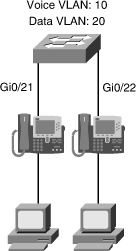
![]() The VLAN architecture is very important, and knowing the voice and data VLANs is crucial. Also, knowing how voice and data traffic is carried across switch ports help in troubleshooting efforts. Figure 8-8 shows that the voice VLAN uses IEEE 802.1Q encapsulation, while data traffic remains untagged and uses the native VLAN. The switch port where the IP phone connects is configured as an access port, but it supports an auxiliary VLAN called the voice VLAN.
The VLAN architecture is very important, and knowing the voice and data VLANs is crucial. Also, knowing how voice and data traffic is carried across switch ports help in troubleshooting efforts. Figure 8-8 shows that the voice VLAN uses IEEE 802.1Q encapsulation, while data traffic remains untagged and uses the native VLAN. The switch port where the IP phone connects is configured as an access port, but it supports an auxiliary VLAN called the voice VLAN.


![]() The design considerations can result in scenarios that need troubleshooting. If the services that the network infrastructure needs to provide are not available, are misconfigured, or are simply not reachable, IP phones might become out of sync in terms of digital certificate verification, or they might not obtain the right amount of power, if CDP is missing. Furthermore, a misconfigured DHCP server might prevent IP phones from obtaining their configuration files if option 150 is not enabled.
The design considerations can result in scenarios that need troubleshooting. If the services that the network infrastructure needs to provide are not available, are misconfigured, or are simply not reachable, IP phones might become out of sync in terms of digital certificate verification, or they might not obtain the right amount of power, if CDP is missing. Furthermore, a misconfigured DHCP server might prevent IP phones from obtaining their configuration files if option 150 is not enabled.
![]() Even if the network services are operational and provide the required support infrastructure, QoS architectures might render voice traffic useless. Furthermore, security controls might interfere with control protocols such as DHCP. They could also filter required signaling protocols, crucial in VoIP operations. It is important to understand the protocols and ports involved in standard IP telephony deployments. Examples of those protocols are Real-Time Transport Protocol (RTP) and its UDP port ranges, Session Initiation Protocol (SIP) on TCP port 5060, or H323 on TCP port 1720.
Even if the network services are operational and provide the required support infrastructure, QoS architectures might render voice traffic useless. Furthermore, security controls might interfere with control protocols such as DHCP. They could also filter required signaling protocols, crucial in VoIP operations. It is important to understand the protocols and ports involved in standard IP telephony deployments. Examples of those protocols are Real-Time Transport Protocol (RTP) and its UDP port ranges, Session Initiation Protocol (SIP) on TCP port 5060, or H323 on TCP port 1720.
![]() On most Cisco IOS devices, you use what is known as Modular QoS CLI (MQC) to configure QoS. MQC offers the configuration objects that implement QoS in a modular fashion, so that you can configure policies once and apply them to multiple interfaces, even different devices (because MQC syntax is not platform specific). It is also modular because it decouples the traffic classification components from the policy components, so that you can apply the same policy to different traffic classes without having to create it multiple times.
On most Cisco IOS devices, you use what is known as Modular QoS CLI (MQC) to configure QoS. MQC offers the configuration objects that implement QoS in a modular fashion, so that you can configure policies once and apply them to multiple interfaces, even different devices (because MQC syntax is not platform specific). It is also modular because it decouples the traffic classification components from the policy components, so that you can apply the same policy to different traffic classes without having to create it multiple times.
![]() QoS configuration in summary, is assigning different treatments to different types of traffic, according to the traffic or application requirements. Figure 8-9 displays the process of configuring a QoS policy using Cisco IOS MQC, which has three main components:
QoS configuration in summary, is assigning different treatments to different types of traffic, according to the traffic or application requirements. Figure 8-9 displays the process of configuring a QoS policy using Cisco IOS MQC, which has three main components:
- Class maps: Class maps are used to create classification templates that are later used in policy maps in which QoS mechanisms are bound to classes. Examples include voice, video, bulk data transfers, and transactional traffic.
- Policy maps: Policy maps are used to create a traffic policy. The purpose of a traffic policy is to configure the QoS features that should be associated with the traffic that has been classified in a user-specified traffic class or classes. Examples of policies applied to specific traffic classes are rate-limit video traffic, reserve bandwidth for voice traffic, and always drop bulk transfers first at moments of heavy congestion.
- Service policy: The service-policy command is used to assign a policy map to an interface or VC with respect to incoming or outgoing traffic. A service policy can also be applied to a class within a policy map, which results in a nested or hierarchical policy.


![]() When the class maps, policy maps, and service policies are configured on the device interfaces and enforce the built QoS policies, the main command used for troubleshooting is the show policy-map interface command, which you will see in action later in Example 8-30.
When the class maps, policy maps, and service policies are configured on the device interfaces and enforce the built QoS policies, the main command used for troubleshooting is the show policy-map interface command, which you will see in action later in Example 8-30.
![]() Troubleshooting converged networks requires the gathering-information stage to include QoS and network services information. The show policy-map interface command is used in the routers, and the show mls qos command is used on the switches, to summarize the status of the QoS components. You much also make use of the appropriate show and debug commands to examine the more traditional services such as DHCP and CDP. Analyzing the potential hypotheses requires an integrated effort. In converged networks, we have to consider issues related to PoE, followed by CDP, followed by DHCP, followed by TFTP, because that is the sequence of events and protocols that allow IP phones to be connected to the network and become operational. You also need to understand that the LAN services that are used to support unified communications are being used in other capacities, too. For example, the DHCP server probably assigns IP addresses to devices other than the IP phones, too, and the NTP service will also be synchronizing router clocks to enable SSH communications. Every time we change any of these services to fix VoIP issues, we might be affecting another protocol or application’s operation.
Troubleshooting converged networks requires the gathering-information stage to include QoS and network services information. The show policy-map interface command is used in the routers, and the show mls qos command is used on the switches, to summarize the status of the QoS components. You much also make use of the appropriate show and debug commands to examine the more traditional services such as DHCP and CDP. Analyzing the potential hypotheses requires an integrated effort. In converged networks, we have to consider issues related to PoE, followed by CDP, followed by DHCP, followed by TFTP, because that is the sequence of events and protocols that allow IP phones to be connected to the network and become operational. You also need to understand that the LAN services that are used to support unified communications are being used in other capacities, too. For example, the DHCP server probably assigns IP addresses to devices other than the IP phones, too, and the NTP service will also be synchronizing router clocks to enable SSH communications. Every time we change any of these services to fix VoIP issues, we might be affecting another protocol or application’s operation.
![]() Table 8-1 shows a list of useful commands used for troubleshooting converged networks. As usual, using the appropriate debug command is crucial. For example, debug ip dhcp server events enables you to look at all DHCP transactions and perform specific troubleshooting for the DHCP protocol. On a router that is acting as a DHCP server, this debug displays all stages of DHCP (discover, offer, request, and acknowledgment) that lead to a client obtaining an IP lease. The debug ephone command is also very informative; it shows the detail of IP phone registration process, including IP phones obtaining power (PoE), IP addresses, and configuration files.
Table 8-1 shows a list of useful commands used for troubleshooting converged networks. As usual, using the appropriate debug command is crucial. For example, debug ip dhcp server events enables you to look at all DHCP transactions and perform specific troubleshooting for the DHCP protocol. On a router that is acting as a DHCP server, this debug displays all stages of DHCP (discover, offer, request, and acknowledgment) that lead to a client obtaining an IP lease. The debug ephone command is also very informative; it shows the detail of IP phone registration process, including IP phones obtaining power (PoE), IP addresses, and configuration files.
|
|
|
|---|---|
|
|
|
|
|
|
|
|
|
|
|
|
|
|
|
Unified Communications Troubleshooting Example: Port Security and Voice VLAN Issues
![]() The first troubleshooting example is based on the network topology diagram shown in Figure 8-10. The problem here is that the IP phones will not boot and initialize. They have no access to the IP network. We are having this problem in multiple areas of the network, but not all of them. The issue seems to be permanent, and not intermittent. In those switches where the problem IP phones are connected, it is not clear whether all IP phones have the same problem.
The first troubleshooting example is based on the network topology diagram shown in Figure 8-10. The problem here is that the IP phones will not boot and initialize. They have no access to the IP network. We are having this problem in multiple areas of the network, but not all of them. The issue seems to be permanent, and not intermittent. In those switches where the problem IP phones are connected, it is not clear whether all IP phones have the same problem.
![]() Knowing from the reported symptoms that this issue seems to be a network-wide problem, the support team decided to identify the wiring closets where the symptoms were detected and try to find a common recent change, upgrade, or incident recently happening. The change logs for the affected wiring closets show a recent change on VLAN Trunking Protocol (VTP) domains and configuration. The support team decided to check the status of the ports for the failing IP phones. In the past, changes such as the VTP change have resulted in unwanted or unneeded configuration changes that fail to get documented.
Knowing from the reported symptoms that this issue seems to be a network-wide problem, the support team decided to identify the wiring closets where the symptoms were detected and try to find a common recent change, upgrade, or incident recently happening. The change logs for the affected wiring closets show a recent change on VLAN Trunking Protocol (VTP) domains and configuration. The support team decided to check the status of the ports for the failing IP phones. In the past, changes such as the VTP change have resulted in unwanted or unneeded configuration changes that fail to get documented.
![]() You begin at the switch, with the show interfaces status command for the interface where the phone is connected. The output, shown in Example 8-21, provides an overall view of port status and basic configuration.
You begin at the switch, with the show interfaces status command for the interface where the phone is connected. The output, shown in Example 8-21, provides an overall view of port status and basic configuration.
Port Name Status Vlan Duplex Speed Type
Gi0/21 to phone number one err-disabled 20 auto auto 10/100/1000BaseTX
Switch#
![]() The err-disable state can have multiple causes: duplex mismatches, late collisions, EtherChannel problems, spanning-tree issues, and so on. You now try the command that complements show interfaces status: show interface status err-disabled. This command lists the ports in this state along with the reasons for this state. Looking at the output on Example 8-22, you can see that the reason for the error is a port security violation.
The err-disable state can have multiple causes: duplex mismatches, late collisions, EtherChannel problems, spanning-tree issues, and so on. You now try the command that complements show interfaces status: show interface status err-disabled. This command lists the ports in this state along with the reasons for this state. Looking at the output on Example 8-22, you can see that the reason for the error is a port security violation.
Port Name Status Reason Err-disabled vlans
Gi0/21 to phone number one err-disabled psecure-violation
Switch#
![]() You must use the port security commands to determine the configuration, and inquire about the need for this feature and the possibility that this configuration was a mistake. If you look at the output of the show port-security interface command in Example 8-23, you see that the maximum allowed MAC addresses setting on the port is set to 1.
You must use the port security commands to determine the configuration, and inquire about the need for this feature and the possibility that this configuration was a mistake. If you look at the output of the show port-security interface command in Example 8-23, you see that the maximum allowed MAC addresses setting on the port is set to 1.
Port Security : Enabled
Port Status : Secure-shutdown
Violation Mode : Shutdown
Aging Time : 0 mins
Aging Type : Absolute
SecureStatic Address Aging : Disabled
Maximum MAC Addresses : 1
Total MAC Addresses : 1
Configured MAC Addresses : 1
Sticky MAC Addresses : 0
Last Source Address:vlan : 0021.7098.30ab:20
Security Violation Count : 1
Switch#
![]() That setting is probably why the problem has occurred. A maximum of one MAC address is allowed in the interface, yet some of the phones have PCs connected to them, and both the phone and the PC send packets. This means that two MAC addresses will be reported on the port, which is beyond the maximum allowed. After investigation, those who were investigating whether the port security feature was needed inform you that this setting is not needed on IP phone switch ports, so you proceed to remove the configuration from all the ports in this switch. To remove the port security configuration, you need to run not just the no switchport port-security command, but also all commands related to port security. You first use the show running interface command to display the whole configuration for the interfaces, and then remove all port security commands as shown in Example 8-24. After the corrections are made, you must reset the interface by entering shutdown before removing the erroneous commands, and entering the no shutdown command after-wards (as shown in Example 8-24). Finally, you check the status of the interface and the status shows as connected.
That setting is probably why the problem has occurred. A maximum of one MAC address is allowed in the interface, yet some of the phones have PCs connected to them, and both the phone and the PC send packets. This means that two MAC addresses will be reported on the port, which is beyond the maximum allowed. After investigation, those who were investigating whether the port security feature was needed inform you that this setting is not needed on IP phone switch ports, so you proceed to remove the configuration from all the ports in this switch. To remove the port security configuration, you need to run not just the no switchport port-security command, but also all commands related to port security. You first use the show running interface command to display the whole configuration for the interfaces, and then remove all port security commands as shown in Example 8-24. After the corrections are made, you must reset the interface by entering shutdown before removing the erroneous commands, and entering the no shutdown command after-wards (as shown in Example 8-24). Finally, you check the status of the interface and the status shows as connected.
Switch# sh run int g0/21
Building configuration...

Current configuration : 200 bytes
!
Interface GigabitEthernet0/21
description to phone number one
switchport access vlan 20
switchport mode access
switchport port-security
switchport port-security mac-address 000b.8572.1810
end

Switch#
Switch#
Switch# conf t
Enter configuration commands, one per line. End with CNTL/Z.
Switch(config)# int g0/21
Switch(config-if)# shutdown
Switch(config-if)# no switchport port-security
Switch(config-if)# no switchport port-security mac-address 000b.8572.1810
Switch(config-if)# no shutdown
Switch(config-if)#end
Switch# sh int g0/21 status

Port    Name                Status       Vlan  Duplex  Speed   Type
Gi0/21  to phone number on  connected    20    a-full  a-1000  10/100/1000BaseTX
Switch#
![]() You hear back from the IP telephony support personnel, and they state that their IP phones are still down. So, you must continue troubleshooting. Scrolling back through the running configuration of the interface, you notice that voice VLAN is not configured for the port. At this point, the support team has provided you with the configuration template for switch ports connecting IP phones to the network. You notice that the interfaces are missing the trust boundary settings and have no voice VLAN configuration, as per the template. Therefore, you should restore interface configurations according to the configuration template. You do that only on one interface to test and verify the changes as shown in Example 8-25: set the voice VLAN using switchport voice vlan 10 and trust IP phone markings using mls qos trust cos and mls qos trust device ip-phone commands. This last command configures CDP so that it can detect whether a Cisco IP phone is attached to the port. If CDP detects a Cisco IP phone, the interface applies the configured mls qos trust cos command. If CDP does not detect a Cisco IP phone, QoS ignores any configured non-default trust state. The configuration work is then checked using the show interfaces switchport command.
You hear back from the IP telephony support personnel, and they state that their IP phones are still down. So, you must continue troubleshooting. Scrolling back through the running configuration of the interface, you notice that voice VLAN is not configured for the port. At this point, the support team has provided you with the configuration template for switch ports connecting IP phones to the network. You notice that the interfaces are missing the trust boundary settings and have no voice VLAN configuration, as per the template. Therefore, you should restore interface configurations according to the configuration template. You do that only on one interface to test and verify the changes as shown in Example 8-25: set the voice VLAN using switchport voice vlan 10 and trust IP phone markings using mls qos trust cos and mls qos trust device ip-phone commands. This last command configures CDP so that it can detect whether a Cisco IP phone is attached to the port. If CDP detects a Cisco IP phone, the interface applies the configured mls qos trust cos command. If CDP does not detect a Cisco IP phone, QoS ignores any configured non-default trust state. The configuration work is then checked using the show interfaces switchport command.
Enter configuration commands, one per line. End with CNTL/Z.
Switch(config)# int g0/21
Switch(config-if)# switchport voice vlan 10
Switch(config-if)# mls qos trust cos
Switch(config-if)# mls qos trust device cisco-phone
Switch(config-if)#
Switch# show interface switchport g0/21
Name: Gi0/21
Switchport: Enabled
Administrative Mode: static access
Operational Mode: static access
Administrative Trunking Encapsulation: negotiate
Operational Trunking Encapsulation: native
Negotiation of Trunking: Off
Access Mode VLAN: 20 (VLAN0020)
Trunking Native Mode VLAN: 1 (default)
Administrative Native VLAN tagging: enabled
Voice VLAN: 10 (VLAN0010)
Administrative private-vlan host association: none
Administrative private-vlan mapping: none
Administrative private-vlan trunk native VLAN: none
Administrative private-vlan trunk Native VLAN tagging: enabled
Administrative private-vlan trunk encapsulation: dot1q
Administrative private-vlan trunk normal VLANs: none
Administrative private-vlan trunk associations: none
Administrative private-vlan trunk mappings: none
Operational private-vlan: none
Trunking VLANs Enabled: ALL
Pruning VLANs Enabled: 2-1001
Capture Mode Disabled
Capture VLANs Allowed: ALL
Protected: false
Unknown unicast blocked: disabled
Unknown multicast blocked: disabled
Appliance trust: none
Switch#
![]() You hear from the support team that the phone has initialized successfully and is now operational, so your job here has been completed. You now proceed with replicating the change to other affected interfaces, and you do similar verifications for those ports.
You hear from the support team that the phone has initialized successfully and is now operational, so your job here has been completed. You now proceed with replicating the change to other affected interfaces, and you do similar verifications for those ports.
| Note |
|
Unified Communications Troubleshooting Example: Invalid Marking of VoIP Packets
![]() The second troubleshooting example of this section is based on the network topology shown in Figure 8-11. In this case, users from one building complain about their experience with voice calls and claim that it is choppy, they lose connections frequently, and at some point voice conversations are intermittent. A cause for the issue has not been documented, and the problem is worse for branch-to-branch calls. Your task is to determine whether the network is to blame, and if it is, locate where the problem is occurring.
The second troubleshooting example of this section is based on the network topology shown in Figure 8-11. In this case, users from one building complain about their experience with voice calls and claim that it is choppy, they lose connections frequently, and at some point voice conversations are intermittent. A cause for the issue has not been documented, and the problem is worse for branch-to-branch calls. Your task is to determine whether the network is to blame, and if it is, locate where the problem is occurring.


![]() The information you have is definitely vague. Part of your job in gathering information is to obtain measurable information. While gathering information, you need to ask the following questions:
The information you have is definitely vague. Part of your job in gathering information is to obtain measurable information. While gathering information, you need to ask the following questions:
- How often do you observe the reported symptoms?
- Is there a particular time of the day in which they commonly occur?
- Is the perceived quality the same when calling internal extension numbers and as it is when calling outside numbers?
- How often are you unable to obtain a dial tone? For how long does this condition remain?
- Which locations of the network are experiencing the problem (building/branch)?
- Are the problematic devices connected to the same wiring closet?
![]() With these answers, you can reduce the scope of our search and make an effective approach to solving the problem. You have enough information to suspect a certain wiring closet where the devices in our diagram are located. All symptoms (intermittent connections, choppy voice, disconnections) seem to be related to QoS. You have obtained baseline numbers for some QoS metrics, and have determined that in fact end-to-end delay for voice traffic has doubled across the campus. Packet-loss percentages are a bit higher than 1 percent, which is around the baseline. The latency numbers are definitely showing that a QoS issue exists. Knowing that the policy trend in this campus is to push QoS settings toward the distribution and access layers, you start at the lower layers and work your way up. This means you will check the access switch first, and then move your way up to the distribution layer switch or router, trying to confirm the QoS settings. This is a follow-the-path strategy.
With these answers, you can reduce the scope of our search and make an effective approach to solving the problem. You have enough information to suspect a certain wiring closet where the devices in our diagram are located. All symptoms (intermittent connections, choppy voice, disconnections) seem to be related to QoS. You have obtained baseline numbers for some QoS metrics, and have determined that in fact end-to-end delay for voice traffic has doubled across the campus. Packet-loss percentages are a bit higher than 1 percent, which is around the baseline. The latency numbers are definitely showing that a QoS issue exists. Knowing that the policy trend in this campus is to push QoS settings toward the distribution and access layers, you start at the lower layers and work your way up. This means you will check the access switch first, and then move your way up to the distribution layer switch or router, trying to confirm the QoS settings. This is a follow-the-path strategy.
![]() Because the switch itself could be a bottleneck, you start by checking global switch settings that might affect QoS, in the hopes of finding the problem there, so that you will not have to check each phone. One of the possible issues is high CPU utilization at the switch level. You use the show processes CPU command (see Example 8-26) and observe that the 5-minute averages go to around 25 percent utilization. This percentage is not bad, especially when compared to a baseline of 34 percent at peak hours. Because you have the QoS baseline, you can compare all the numbers you gather.
Because the switch itself could be a bottleneck, you start by checking global switch settings that might affect QoS, in the hopes of finding the problem there, so that you will not have to check each phone. One of the possible issues is high CPU utilization at the switch level. You use the show processes CPU command (see Example 8-26) and observe that the 5-minute averages go to around 25 percent utilization. This percentage is not bad, especially when compared to a baseline of 34 percent at peak hours. Because you have the QoS baseline, you can compare all the numbers you gather.
CPU utilization for five seconds: 99%/22%; one minute: 58%, five minutes: 25%
PID Runtime(ms) Invoked uSecs 5Sec 1Min 5Min TTY Process
1 0 15 0 0.00% 0.00% 0.00% 0 Chunk Manager
2 9 1131 7 0.00% 0.00% 0.00% 0 Load Meter
3 0 1 0 0.00% 0.00% 0.00% 0 CEF RP IPC Backg
4 8308 772 10761 0.00% 0.13% 0.11% 0 Check heaps
5 0 1 0 0.00% 0.00% 0.00% 0 Pool Manager
6 0 2 0 0.00% 0.00% 0.00% 0 Timers
7 0 1 0 0.00% 0.00% 0.00% 0 Image Licensing
8 0 2 0 0.00% 0.00% 0.00% 0 License Client N
9 2088 20 104400 2.39% 0.19% 0.04% 0 Licensing Auto U
10 0 1 0 0.00% 0.00% 0.00% 0 Crash writer
11 67769 15394 4402 56.70% 32.81% 12.60% 0 ARP Input
12 0 1 0 0.00% 0.00% 0.00% 0 CEF MIB API
13 0 1 0 0.00% 0.00% 0.00% 0 AAA_SERVER_DEADT
14 0 2 0 0.00% 0.00% 0.00% 0 AAA high-capacit
15 0 1 0 0.00% 0.00% 0.00% 0 Policy Manager
16 8 5 1600 0.00% 0.00% 0.00% 0 Entity MIB API
17 0 1 0 0.00% 0.00% 0.00% 0 IFS Agent Manage
18 96 345 0 0.00% 0.00% 0.00% 0 IPC Dynamic Cach
![]() The next step is a port-by-port analysis. The interface Gi0/11 has a phone attached to it. Therefore, you use the show interface command and inspect its bandwidth utilization averages, and as shown in Example 8-27, they are at around 1.5 percent of the total interface bandwidth (15 Mbps/1 Gbps). The other reported numbers on this output do not look bad either.
The next step is a port-by-port analysis. The interface Gi0/11 has a phone attached to it. Therefore, you use the show interface command and inspect its bandwidth utilization averages, and as shown in Example 8-27, they are at around 1.5 percent of the total interface bandwidth (15 Mbps/1 Gbps). The other reported numbers on this output do not look bad either.
5 minute input rate 729000 bits/sec, 847 packets/sec
5 minute output rate 14150000 bits/sec, 1129 packets/sec
104911 packets input, 13035040 bytes, 0 no buffer
Received 22020 broadcasts (110 multicasts)
0 runts, 0 giants, 0 throttles
0 input errors, 0 CRC, 0 frame, 0 overrun, 0 ignored
0 watchdog, 114 multicast, 0 pause input
0 input packets with dribble condition detected
225001 packets output, 41332141 bytes, 0 underruns
0 output errors, 0 collisions, 0 interface resets
0 babbles, 0 late collision, 0 deferred
0 lost carrier, 0 no carrier, 0 PAUSE output
0 output buffer failures, 0 output buffers swapped out
![]() The next things you need to investigate are the trunks, which aggregate traffic uplink to the distribution layer. Therefore, you use the show interface command for the uplink trunk interfaces, too, and discover that utilization is naturally higher, but it is consistent with the numbers recorded in the baseline (see Example 8-28).
The next things you need to investigate are the trunks, which aggregate traffic uplink to the distribution layer. Therefore, you use the show interface command for the uplink trunk interfaces, too, and discover that utilization is naturally higher, but it is consistent with the numbers recorded in the baseline (see Example 8-28).
GigabitEthernet0/13 is up, line protocol is up (connected)
Hardware is Gigabit Ethernet, address is 0023.5d08.568d (bia 0023.5908.568d)
Description: to Cisco phone
MTU 1504 bytes, BW 100000 Kbit, DLY 100 usec,
reliability 255/255, txload 5/255, rxload 6/255
Encapsulation ARPA, loopback not set
Keepalive set (10 sec)
Full-duplex, 100Mb/s, media type is 10/100/1000BaseTX
input flow-control is off, output flow-control is unsupported
ARP type:ARPA, ARP Timeout 04:00:00
Last input 00:00:10, output 00:00:00, output hang never
Last clearing of "show interface" counters 00:10:45
Input queue: 0/75/0/0 (size/max/drops/flushes); Total output drops: 0
Queueing strategy: fifo
Output queue: 0/40 (size/max)
5 minute input rate 2478000 bits/sec, 1642 packets/sec
5 minute output rate 2194000 bits/sec, 690 packets/sec
917323 packets input, 171833916 bytes, 0 no buffer
Received 913155 broadcasts (26001 multicasts)
0 runts, 0 giants, 0 throttles
--More--
![]() You should now shift your focus to QoS. QoS is about managing business and technical priorities, to prioritize critical traffic and provide appropriate levels of service to it. At peak congestion times, if all traffic is treated equally, all traffic classes will probably suffer. Therefore, typically you assign priorities to different traffic classes. You should check and see whether the QoS classes, and their corresponding markings, are being enforced in the network. From the documentation, you learn that IP phones represent the trust boundary, and that the DSCP markings are being used throughout the network. Phones are allowed to tag their own packets with high priorities, in this instance DSCP value EF (Expedited Forwarding). You should check and see whether the switch ports are maintaining those tags, and not resetting them. Using the command show mls qos interface on one of the ports pointing to the phones reveals that the port is indeed trusted and that DSCP values are being maintained and not reset, as shown in Example 8-29.
You should now shift your focus to QoS. QoS is about managing business and technical priorities, to prioritize critical traffic and provide appropriate levels of service to it. At peak congestion times, if all traffic is treated equally, all traffic classes will probably suffer. Therefore, typically you assign priorities to different traffic classes. You should check and see whether the QoS classes, and their corresponding markings, are being enforced in the network. From the documentation, you learn that IP phones represent the trust boundary, and that the DSCP markings are being used throughout the network. Phones are allowed to tag their own packets with high priorities, in this instance DSCP value EF (Expedited Forwarding). You should check and see whether the switch ports are maintaining those tags, and not resetting them. Using the command show mls qos interface on one of the ports pointing to the phones reveals that the port is indeed trusted and that DSCP values are being maintained and not reset, as shown in Example 8-29.
GigabitEthernet0/11
trust state: trust dscp
trust mode: trust dscp
trust enabled flag: ena
COS override: dis
Default COS: 0
DSCP Mutation Map: Default DSCP Mutation Map
Trust device: none
qos mode: port-based
Switch1#
![]() You can conclude that the access switch is configured properly. Next, you move up along the path of the traffic. The distribution layer in this network is collapsed at the branch router level. That will be the next focus and you will verify QoS settings on that device, the router. You use the show policy-map interface command on the router and observe the results as shown in Example 8-30.
You can conclude that the access switch is configured properly. Next, you move up along the path of the traffic. The distribution layer in this network is collapsed at the branch router level. That will be the next focus and you will verify QoS settings on that device, the router. You use the show policy-map interface command on the router and observe the results as shown in Example 8-30.
FastEthernet0/0
Service-policy input: reclassify
Class-map: signaling (match-any)
0 packets, 0 bytes
5 minute offered rate 0 bps, drop rate 0 bps
Match: protocol h323
0 packets, 0 bytes
5 minute rate 0 bps
Match: protocol sip
0 packets, 0 bytes
5 minute rate 0 bps
Match: protocol mgcp
0 packets, 0 bytes
5 minute rate 0 bps
QoS set
dscp af11
Packets marked 0
Class-map: voice (match-all)
0 packets, 0 bytes
5 minute offered rate 0 bps, drop rate 0 bps
Match: protocol rtp audio
QoS Set
dscp af31
Packets marked 0
Class-map: management (match-all)
0 packets, 0 bytes
5 minute offered rate 0 bps, drop rate 0 bps
Match: telnet
Match: snmp
Match: ssh
QoS Set
dscp cs2
Packets marked 0
Class-map: class-default (match-any)
12 packets, 1516 bytes
5 minute offered rate 0 bps, drop rate 0 bps
Match: any
QoS Set
dscp default
Packets marked 12
![]() There is a policy called reclassify attached to the router fa0/0 interface. The name suits the purpose; it looks like people are trying to reclassify and re-mark packets coming into this interface. That makes sense because this device is the WAN edge device, and the service provider may require a different marking to maintain QoS policies in their network.
There is a policy called reclassify attached to the router fa0/0 interface. The name suits the purpose; it looks like people are trying to reclassify and re-mark packets coming into this interface. That makes sense because this device is the WAN edge device, and the service provider may require a different marking to maintain QoS policies in their network.
![]() However, the “QoS Set” section within the VOICE class tells us that VOICE is being reclassified and tagged with the DSCP value AF31. This value is strange; voice traffic is typically classified with DSCP value EF, the highest priority. In this instance, it looks like the voice traffic class is being reclassified into a lower priority. When you verify this fact with the QoS team, they confirm your suspicion. Voice is being incorrectly marked down (toaf31). The impact of this improper remarking is that QoS policies such as bandwidth reservation, priority queuing, and preferred path selection shall not be enforced. Voice traffic is suffering because of the identified voice remarking mistake. Once this error is fixed, you are notified that the problems are now all solved.
However, the “QoS Set” section within the VOICE class tells us that VOICE is being reclassified and tagged with the DSCP value AF31. This value is strange; voice traffic is typically classified with DSCP value EF, the highest priority. In this instance, it looks like the voice traffic class is being reclassified into a lower priority. When you verify this fact with the QoS team, they confirm your suspicion. Voice is being incorrectly marked down (toaf31). The impact of this improper remarking is that QoS policies such as bandwidth reservation, priority queuing, and preferred path selection shall not be enforced. Voice traffic is suffering because of the identified voice remarking mistake. Once this error is fixed, you are notified that the problems are now all solved.
| Note |
|
Unified Communications Troubleshooting Example: ACL and Trunk Issues
![]() The third troubleshooting example is based on the network topology shown in Figure 8-12. A recent security audit has resulted in new security policies being put in place. The network team failed previous audits, so this time they are committed to enforcing security end to end. This enforcement seems to have affected our branch, because now the IP phones are not able to initialize and obtain their base configuration. Those settings are obtained from configuration files stored in the TFTP server, which is the local branch router. The local branch router is also serving as a call agent, performing call routing, Call Admission Control (CAC), and other IP telephony functions. In applying a troubleshooting method, you have perhaps more information to work with than with the previous examples. Investigating the recent change in security policy, you find that Cisco IOS firewall services were installed in some key routers of the network. The auditor recommended network locations with higher levels of risk. This recommendation included certain power branches that were deemed vulnerable because of their recent history of being the source of worm outbreaks. This line of thinking allows you to focus on the Cisco IOS firewall, without discarding the possibility of other issues. Therefore, instead of focusing on a bottom-up or top-down approach, you start at the firewall level and analyze the implications of it on the unified communications infrastructure.
The third troubleshooting example is based on the network topology shown in Figure 8-12. A recent security audit has resulted in new security policies being put in place. The network team failed previous audits, so this time they are committed to enforcing security end to end. This enforcement seems to have affected our branch, because now the IP phones are not able to initialize and obtain their base configuration. Those settings are obtained from configuration files stored in the TFTP server, which is the local branch router. The local branch router is also serving as a call agent, performing call routing, Call Admission Control (CAC), and other IP telephony functions. In applying a troubleshooting method, you have perhaps more information to work with than with the previous examples. Investigating the recent change in security policy, you find that Cisco IOS firewall services were installed in some key routers of the network. The auditor recommended network locations with higher levels of risk. This recommendation included certain power branches that were deemed vulnerable because of their recent history of being the source of worm outbreaks. This line of thinking allows you to focus on the Cisco IOS firewall, without discarding the possibility of other issues. Therefore, instead of focusing on a bottom-up or top-down approach, you start at the firewall level and analyze the implications of it on the unified communications infrastructure.


![]() The reported symptom is that the IP phones cannot initialize and obtain their settings, or make calls. While gathering information about the Cisco IOS firewall, you must remember that Cisco IOS Software allows the firewall configuration using two methods:
The reported symptom is that the IP phones cannot initialize and obtain their settings, or make calls. While gathering information about the Cisco IOS firewall, you must remember that Cisco IOS Software allows the firewall configuration using two methods:
- The classical Cisco IOS firewall, which uses ACLs exclusively on interfaces
- The zone-based firewall, which is more widely used and it is more flexible for a comprehensive deployment of firewall rules
![]() You could check both of them starting at the access switch (Switch1). Using the show zone-pair security command will tell you whether the zone-based firewall is configured. You can see in the output shown in Example 8-31 that there are no policies of this kind, so this firewall is probably a classic firewall. Using the show access-lists command on the switch reveals that no ACLs are configured there.
You could check both of them starting at the access switch (Switch1). Using the show zone-pair security command will tell you whether the zone-based firewall is configured. You can see in the output shown in Example 8-31 that there are no policies of this kind, so this firewall is probably a classic firewall. Using the show access-lists command on the switch reveals that no ACLs are configured there.
^
%Invalid input detected at '^' marker.
Switch1# show access-lists
Switch1#
![]() You move on to the router (Router1) and do the same verification. On this particular router, the show zone-pair security command is also not supported. You use the show ip interfaces command, which displays the access lists that are applied to each interface and the direction in which they are applied as shown in Example 8-32. An ACL called FIREWALL is applied to the fa0/0 interface. This interface is the interface that points to the access switch and the IP phones.
You move on to the router (Router1) and do the same verification. On this particular router, the show zone-pair security command is also not supported. You use the show ip interfaces command, which displays the access lists that are applied to each interface and the direction in which they are applied as shown in Example 8-32. An ACL called FIREWALL is applied to the fa0/0 interface. This interface is the interface that points to the access switch and the IP phones.
FastEthernet0/0 is up, line protocol is up
Internet address is 10.10.10.1/24
Broadcast address is 255.255.255.255
Address determined by non-volatile memory
MTU is 1500 bytes
Helper address is not set
Directed broadcast forwarding is disabled
Outgoing access list is not set
Inbound access list is FIREWALL
Proxy ARP is enabled
Local Proxy ARP is disabled
Security level is default
Split horizon is enabled
ICMP redirects are always sent
ICMP unreachables are always sent
ICMP mask replies are never sent
IP fast switching is enabled
IP fast switching on the same interface is disabled
IP Flow switching is disabled
--More--
![]() Now you display the access list itself (shown in Example 8-33). The ACL looks simple, yet comprehensive, allowing traditional traffic such as HTTP and FTP, and management protocols such as SSH. The ACL looks like a closed policy: Allow what you need, deny everything else. That might point to the problem; whoever designed the security policy was not fully aware of the legitimate services and applications running on the network.
Now you display the access list itself (shown in Example 8-33). The ACL looks simple, yet comprehensive, allowing traditional traffic such as HTTP and FTP, and management protocols such as SSH. The ACL looks like a closed policy: Allow what you need, deny everything else. That might point to the problem; whoever designed the security policy was not fully aware of the legitimate services and applications running on the network.
Standard IP access list 23
10 permit 10.10.10.0, wildcard bits 0.0.0.7
20 permit 172.29.128.128, wildcard bits 0.0.0.31
30 permit 10.10.50.0, wildcard bits 0.0.0.255 (2 matches)
40 permit 10.10.60.0, wildcard bits 0.0.0.255
Extended IP access list FIREWALL
10 permit tcp any any eq telnet (500 matches)
20 permit tcp any any eq 22
30 permit tcp any host 10.10.60.60 eq www
40 permit tcp any host 10.10.60.60 eq 443
50 permit udp any any
Router1#
![]() At this point, you must confirm with the IP telephony support team the exact process that an IP phone follows to become operational. The IP phone registers to the router using Skinny Client Control Protocol (SCCP), which is also referred to as “Skinny.” SCCP runs over TCP and uses port 2000. This issue is one of the culprits you are facing. You need to change the access list to allow the SCCP traffic. You simply add a permit line at the end allowing TCP 2000, as shown in Example 8-34
At this point, you must confirm with the IP telephony support team the exact process that an IP phone follows to become operational. The IP phone registers to the router using Skinny Client Control Protocol (SCCP), which is also referred to as “Skinny.” SCCP runs over TCP and uses port 2000. This issue is one of the culprits you are facing. You need to change the access list to allow the SCCP traffic. You simply add a permit line at the end allowing TCP 2000, as shown in Example 8-34
Enter configuration commands, one per line. End with CNTL/Z.
Router1(config)# ip access-list extended FIREWALL
Router1(config-ext-nacl)# permit tcp any any eq 2000
Router1(config-ext-nacl)# end
Router1#
![]() For testing, you initiate one of the IP phones and see whether it is able to make calls. Here, you can make use of the debug ephone register command that belongs to the Cisco Unified Communications Manager Express product, the software on the router that performs call routing and other IP telephony capabilities. The output of the debug ephone register helps you determine whether phones are at least trying to register and obtain their settings from Cisco Unified Communications Manager Express. You initialize the phone and the debug displays no output (see Example 8-35). The phones are still not registering.
For testing, you initiate one of the IP phones and see whether it is able to make calls. Here, you can make use of the debug ephone register command that belongs to the Cisco Unified Communications Manager Express product, the software on the router that performs call routing and other IP telephony capabilities. The output of the debug ephone register helps you determine whether phones are at least trying to register and obtain their settings from Cisco Unified Communications Manager Express. You initialize the phone and the debug displays no output (see Example 8-35). The phones are still not registering.
EPHONE registration debugging is enabled
Router1#
![]() You now follow the link along the voice traffic path. The next step in the troubleshooting process should be to determine whether the trunk between the access switch and the router is allowing SCCP traffic. You need to make sure that the voice VLAN is allowed across the trunk from the switch to the router, and you use the show interfaces trunk command to discover this information, as demonstrated in Example 8-36. You can see that the voice VLAN10 is not allowed across the trunk. That is why voice traffic is not going through it. You can easily fix the problem by going into the trunk interface and entering the switchport trunk allowed vlan add 10 command (also shown in Example 8-36).
You now follow the link along the voice traffic path. The next step in the troubleshooting process should be to determine whether the trunk between the access switch and the router is allowing SCCP traffic. You need to make sure that the voice VLAN is allowed across the trunk from the switch to the router, and you use the show interfaces trunk command to discover this information, as demonstrated in Example 8-36. You can see that the voice VLAN10 is not allowed across the trunk. That is why voice traffic is not going through it. You can easily fix the problem by going into the trunk interface and entering the switchport trunk allowed vlan add 10 command (also shown in Example 8-36).
Port Mode Encapsulation Status Native vlan
Fa0/0 on 802.1q trunking 50
Port Vlans allowed on trunk
Fa0/0 1,50,60
Port Vlans allowed and active in management domain
Fa0/0 1,50,60
Port Vlans in spanning tree forwarding state and not pruned
Fa0/0 1,50,60
Switch1# conf t
Enter configuration commands, one per line. End with CNTL/Z.
Switch1(config)# int Fa0/0
Switch1(config-if)# switchport trunk allowed vlan add 10
Switch1(config-if)# end
Switch1#
![]() The best way to know if you fixed the problem is to see the telephone registering to the router and obtaining its IP telephony settings. You switch back to the router console, and the debug ephone register is still enabled. Example 8-37 shows the results. You clearly see the phone activity messages that indicate the phone has successfully registered. The problem is now solved.
The best way to know if you fixed the problem is to see the telephone registering to the router and obtaining its IP telephony settings. You switch back to the router console, and the debug ephone register is still enabled. Example 8-37 shows the results. You clearly see the phone activity messages that indicate the phone has successfully registered. The problem is now solved.
totalButtonCount=2 buttonOffset=0
*Sep 1 17:22:37.155: ephone-1[0/1][SEP0023331B9090]:Configured 0 speed dial buttons
*Sep 1 17:22:37.159: ephone-1[0/1]:StationSoftKeyTemplateReqMessage
*Sep 1 17:22:37.159: ephone-1[0/1]:StationSoftKeyTemplateReqMessage
*Sep 1 17:22:37.171: ephone-1[0/1]:StationSoftKeySetReqMessage
*Sep 1 17:22:37.171: ephone-1[0/1]:StationSoftKeySetReqMessage
*Sep 1 17:22:37.175: ephone-1[0/1][SEP0023331B9090]:StationLineStatReqMessage from
ephone line 2
*Sep 1 17:22:37.175: ephone-1[0/1][SEP0023331B9090]:StationLineStatReqMessage from
ephone line 2 Invalid DN -1
*Sep 1 17:22:37.175: ephone-1[0/1][SEP0023331B9090]:StationLineStatResMessage sent
to ephone (1 of 2)
*Sep 1 17:22:37.175: ephone-1[0/1][SEP0023331B9090]:StationLineStatReqMessage from
ephone line 1
*Sep 1 17:22:37.179: ephone-1[0/1]:StationLineStatReqMessage ephone line 1 DN 1 =
1000 desc = 1000 label =
*Sep 1 17:22:37.179: ephone-1[0/1]:StationLineStatResMessage sent to ephone (2 of 2)
*Sep 1 17:22:37.179: ephone-1[0/1]:SkinnyCompleteRegistration
*Sep 1 17:22:37.195: ephone-1[0/1][SEP0023331B9090]:Skinny Available Lines 2 set
for socket [1]
*Sep 1 17:22:37.195: ephone-1[0/1]:Already done SkinnyCompleteRegistration
0 comments
Post a Comment