IP Version 4 (IPv4) allows end systems to communicate and forms the foundation of the Internet as we know it today. However, IPv4 has many limitations. IP Version 6 (IPv6) is a technology developed to overcome these limitations.
![]() This chapter introduces IPv6 and the IPv6 addressing scheme and explores how IPv6 addresses are configured. Routing protocols that support IPv6 are explored in detail, as is IPv6 policy routing and route redistribution. The chapter concludes with a discussion of how IPv4 networks can be transitioned to IPv6, including dual-stack, tunneling, and translation techniques.
This chapter introduces IPv6 and the IPv6 addressing scheme and explores how IPv6 addresses are configured. Routing protocols that support IPv6 are explored in detail, as is IPv6 policy routing and route redistribution. The chapter concludes with a discussion of how IPv4 networks can be transitioned to IPv6, including dual-stack, tunneling, and translation techniques.
 Introducing IPv6
![]() The ability to scale networks for future demands requires a limitless supply of IP addresses and improved mobility. IPv6 combines expanded addressing with a more efficient and feature-rich header to meet these demands. While it has many similarities to IPv4, IPv6 satisfies the increasingly complex requirements of hierarchical addressing that IPv4 does not support.
The ability to scale networks for future demands requires a limitless supply of IP addresses and improved mobility. IPv6 combines expanded addressing with a more efficient and feature-rich header to meet these demands. While it has many similarities to IPv4, IPv6 satisfies the increasingly complex requirements of hierarchical addressing that IPv4 does not support.
| Note |
|
![]() This section reviews IPv4 issues that led to the IPv6 design, introduces the key features and benefits of IPv6, and describes the IPv6 packet header. The Cisco IOS supports IPv6 in Release 12.2(2)T and later.
This section reviews IPv4 issues that led to the IPv6 design, introduces the key features and benefits of IPv6, and describes the IPv6 packet header. The Cisco IOS supports IPv6 in Release 12.2(2)T and later.
 IPv4 Issues
![]() As mentioned, IPv6 was designed to overcome issues associated with IPv4, including the following:
As mentioned, IPv6 was designed to overcome issues associated with IPv4, including the following:
-
 Address depletion—One of the major shortcomings of IPv4 is its limited amount of address space. The explosion of new IP-enabled devices, the growth of undeveloped regions, and the rapid growth of other regions have fueled the need for more addresses. In the United States, the Department of Defense (DoD) is a primary driver for the adoption of IPv6 and had set a date of 2008 for all systems to be migrated to this new standard. However, this migration has really only just started.
-
 Of course, all other industries are potential IPv6 users, including education, government agencies, enterprises, service providers, home networks, consumer appliances, distributed online gaming, voice services, and wireless services.
 -
 The number of Internet users is growing extremely fast; there were approximately 973 million users as of November 2005, and 1.7 billion by the end of 2009. The Internet will be transformed after IPv6 fully replaces its less-versatile parent years from now. Nevertheless, IPv4 is in no danger of disappearing overnight. Rather, it will coexist with and then gradually be replaced by IPv6. This change has already begun, particularly in Europe, Japan, and the Asia Pacific. These areas of the world are exhausting their allotted IPv4 addresses, which makes IPv6 all the more attractive. As noted, in addition to its technical and business potential, IPv6 offers a virtually unlimited supply of IP addresses, enough to allocate more than the entire IPv4 Internet address space to everyone on the planet.
 -
 Internet routing table expansion—As more nodes come online, the Internet routing tables continue to grow. These large tables require a lot of processing power, memory, and overhead when stored within the Internet routers.
Note  According to the CIDR Report (http://www.cidr-report.org/as2.0/), there were over 310,000 active Border Gateway Protocol (BGP) entries in Internet routers at the beginning of 2010. This has grown from 200,000 at the beginning of 2007.
-
-
 Lack of true end-to-end model—IPv4 networks typically use Network Address Translation (NAT) as the solution to address depletion. However, NAT hides the true source address of traffic, which can cause other issues. (NAT does, however, provide some security advantages because it provides a layer of anonymity.)
![]() As of January 2010, only 10 percent of the IPv4 addresses remain unallocated. As mentioned, the U.S. DoD is migrating to IPv6, but in North America there is not the sense of urgency felt in other parts of the world, because North American organizations have many IPv4 addresses allocated to them. Governments and organizations in other parts of the world do not have the luxury of having as many IPv4 addresses, and are thus making the transition to IPv6 more quickly.
As of January 2010, only 10 percent of the IPv4 addresses remain unallocated. As mentioned, the U.S. DoD is migrating to IPv6, but in North America there is not the sense of urgency felt in other parts of the world, because North American organizations have many IPv4 addresses allocated to them. Governments and organizations in other parts of the world do not have the luxury of having as many IPv4 addresses, and are thus making the transition to IPv6 more quickly.
 Features of IPv6
![]() IPv6 is a powerful enhancement to IPv4 with features that better suit current and foreseeable network demands, including the following:
IPv6 is a powerful enhancement to IPv4 with features that better suit current and foreseeable network demands, including the following:
-
 Larger address space— IPv6 addresses are 128 bits, compared to IPv4’s 32 bits. This larger address space provides several benefits, including improved global reachability and flexibility, the ability to aggregate prefixes that are announced in routing tables, and easier multihoming to several Internet service providers (ISPs).
 -
 Elimination of public-to-private NAT— The larger address space allows end-to-end communication without NAT.
 -
 Elimination of broadcast addresses— IPv6 includes unicast addresses (one to one), multicast addresses (one to many), and a new type called anycast addresses (one to nearest). IPv6 does not have broadcast addresses.
 -
 Simplified header for improved router efficiency— A simpler header provides several advantages over IPv4, including improved routing efficiency for performance and forwarding-rate scalability, no requirement for processing checksums, simpler and more efficient extension header mechanisms, and flow labels for per-flow processing with no need to examine the transport layer information to identify the various traffic flows.
 -
 Support for mobility and security— Mobility and security help ensure compliance with mobile IP and IPsec standards.
![]() Mobility enables people to move around in networks with mobile network devices, with many having wireless connectivity. Mobile IP is an Internet Engineering Task Force (IETF) standard available for both IPv4 and IPv6 that enables mobile devices to move without breaks in established network connections. Because IPv4 does not automatically provide this kind of mobility, supporting it requires additional configurations.
Mobility enables people to move around in networks with mobile network devices, with many having wireless connectivity. Mobile IP is an Internet Engineering Task Force (IETF) standard available for both IPv4 and IPv6 that enables mobile devices to move without breaks in established network connections. Because IPv4 does not automatically provide this kind of mobility, supporting it requires additional configurations.
![]() In IPv6, mobility is built in, which means that any IPv6 node can use it when necessary. The routing headers of IPv6 make mobile IPv6 much more efficient for end nodes than mobile IPv4 does.
In IPv6, mobility is built in, which means that any IPv6 node can use it when necessary. The routing headers of IPv6 make mobile IPv6 much more efficient for end nodes than mobile IPv4 does.
![]() IPsec is the IETF standard for IP network security, available for both IPv4 and IPv6. Although the functions are essentially identical in both environments, IPsec support is mandatory in IPv6. IPsec is enabled and is available for use on every IPv6 node, making the IPv6 Internet more secure. IPsec may use keys for each device, which implies global key deployment and distribution.
IPsec is the IETF standard for IP network security, available for both IPv4 and IPv6. Although the functions are essentially identical in both environments, IPsec support is mandatory in IPv6. IPsec is enabled and is available for use on every IPv6 node, making the IPv6 Internet more secure. IPsec may use keys for each device, which implies global key deployment and distribution.
-
 Transition richness— There are a variety of ways to transition IPv4 to IPv6.
 One approach is to have a dual stack, with both IPv4 and IPv6 configured on the interface of a network device. In this scenario, both IPv4 and IPv6 run simultaneously.
 Another technique uses an IPv4 tunnel to carry IPv6 traffic. Implementations include IPv6-to-IPv4 (6to4) tunneling and IPv4-compatible tunneling.
 Cisco IOS Software Release 12.3(2)T (and later) also allows NAT protocol translation (NAT-PT) between IPv6 and IPv4, providing direct communication between hosts that are using the different protocol suites.
![]() Fortunately the transition to IPv6 from IPv4 does not have to happen overnight; rather, it can be a gradual change. For example, enterprises can keep their internal networks running IPv4 while simultaneously supporting both protocols on their external web servers. As more applications and web sites move to supporting IPv6, enterprises can gradually transition their internal networks, until they are completely IPv6.
Fortunately the transition to IPv6 from IPv4 does not have to happen overnight; rather, it can be a gradual change. For example, enterprises can keep their internal networks running IPv4 while simultaneously supporting both protocols on their external web servers. As more applications and web sites move to supporting IPv6, enterprises can gradually transition their internal networks, until they are completely IPv6.
![]() Many organizations that have a large number of users, and many countries, including those in the Asia Pacific, have already started aggressively adopting IPv6, because they are running out of IPv4 addresses. For example, the IPv6 Promotion Council of Japan includes many working groups such as those for security and certification of IPv6 products. In China, IPv6 was used for some of the systems at the 2008 Olympics.
Many organizations that have a large number of users, and many countries, including those in the Asia Pacific, have already started aggressively adopting IPv6, because they are running out of IPv4 addresses. For example, the IPv6 Promotion Council of Japan includes many working groups such as those for security and certification of IPv6 products. In China, IPv6 was used for some of the systems at the 2008 Olympics.
![]() IPv6 addresses also provide flexibility not found in IPv4, including the following features:
IPv6 addresses also provide flexibility not found in IPv4, including the following features:
-
 Stateless autoconfiguration— IPv6 provides address autoconfiguration that includes the device’s data link layer address in the IPv6 address for “plug-and-play” functionality. (A version of the stateful dynamic host control protocol [DHCP] is also provided; the DHCP server keeps track of the state of the DHCP client.)
 -
 Prefix renumbering— IPv6 allows simplified mechanisms for address and prefix renumbering. The router advertises the new prefix and the other devices on the network can begin to use the new information. This process can be made nondisruptive to the hosts on the network by manipulating valid and preferred timers for each IPv6 address.
 -
 Multiple addresses per interface— IPv6 interfaces can have multiple addresses of various types assigned to them; these addresses can be used simultaneously.
 -
 Link-local addresses— IPv6 devices automatically create a link-local address on each interface; these addresses are used for many purposes. For example, the interior gateway protocols (IGPs) use a link-local address as the next hop when they are exchanging routing updates.
 -
 Provider-dependent or provider-independent addressing— Because there are so many addresses available, enterprises can use addresses from an ISP, or use their own provider-independent addressing space.
 IPv6 Packet Header
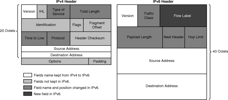
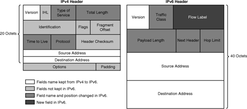
![]() As shown in Figure 8-1, the IPv6 header has 40 octets, in contrast to the 20 octets in the IPv4 header. IPv6 has fewer fields, and the header is 64-bit aligned to enable fast, efficient, hardware-based processing. The IPv6 address fields are four times larger than in IPv4.
As shown in Figure 8-1, the IPv6 header has 40 octets, in contrast to the 20 octets in the IPv4 header. IPv6 has fewer fields, and the header is 64-bit aligned to enable fast, efficient, hardware-based processing. The IPv6 address fields are four times larger than in IPv4.
![]() The IPv4 header contains 12 basic header fields, followed by an options field and a data portion (which usually includes a transport layer segment). The basic IPv4 header has a fixed size of 20 octets, and the variable-length options field increases the size of the total IP header. IPv6 contains fields similar to 7 of the 12 IPv4 basic header fields (5 plus the source and destination address fields), but does not require the other fields.
The IPv4 header contains 12 basic header fields, followed by an options field and a data portion (which usually includes a transport layer segment). The basic IPv4 header has a fixed size of 20 octets, and the variable-length options field increases the size of the total IP header. IPv6 contains fields similar to 7 of the 12 IPv4 basic header fields (5 plus the source and destination address fields), but does not require the other fields.
![]() The IPv6 header contains the following fields:
The IPv6 header contains the following fields:
-
 Version— A 4-bit field, the same as in IPv4. For IPv6, this field contains the number 6. For IPv4, this field contains the number 4.
 -
 Traffic class— An 8-bit field similar to the Type of Service (ToS) field in IPv4. This field tags the packet with a traffic class that it uses in differentiated services (DiffServ) quality of service (QoS). These functionalities are the same for IPv6 and IPv4.
 -
 Flow label— This 20-bit field is new in IPv6. It can be used by the source of the packet to tag the packet as being part of a specific flow, allowing multilayer switches and routers to handle traffic on a per-flow basis rather than per-packet, for faster packet-switching performance. This field can also be used to provide QoS.
 -
 Payload length— This 16-bit field, allowing payloads of up to 64 kilobytes (kB), is similar to the IPv4 total length field.
 -
 Next header— The value of this 8-bit field determines the type of information that follows the basic IPv6 header. It can be a transport-layer packet, such as Transmission Control Protocol (TCP) or User Datagram Protocol (UDP), or it can be an extension header. The next header field is similar to the protocol field of IPv4.
 -
 Hop limit— This 8-bit field specifies the maximum number of hops that an IP packet can traverse. Similar to the Time To Live (TTL) field in IPv4, each router decreases this field by one. Because there is no checksum in the IPv6 header, an IPv6 router can decrease the field without recomputing the checksum, whereas in IPv4 routers, the recomputation uses processing time. If this field ever reaches zero, a message is sent back to the source of the packet and the packet is discarded.
 -
 Source address— This field has 16 octets or 128 bits. It identifies the source of the packet.
 -
 Destination address— This field has 16 octets or 128 bits. It identifies the destination of the packet.
 -
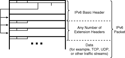
 Extension headers— The extension headers, if any, and the data portion of the packet follow the other eight fields. The Next header field defines the type of the next extension header. The number of extension headers is not fixed, so the total length of the extension header chain is variable.
![]() Notice that the IPv6 header does not have a header checksum field. Because link-layer technologies perform checksum and error control and are considered relatively reliable, an IP header checksum is considered to be redundant. Without the IP header checksum, upper-layer checksums, such as within UDP, are mandatory with IPv6.
Notice that the IPv6 header does not have a header checksum field. Because link-layer technologies perform checksum and error control and are considered relatively reliable, an IP header checksum is considered to be redundant. Without the IP header checksum, upper-layer checksums, such as within UDP, are mandatory with IPv6.
Extension Headers
![]() IPv6 has extension headers that handle options more efficiently and enable a faster forwarding rate and faster processing by end-nodes. The next header field points to the next header in the chain, as shown in Figure 8-2.
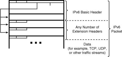
IPv6 has extension headers that handle options more efficiently and enable a faster forwarding rate and faster processing by end-nodes. The next header field points to the next header in the chain, as shown in Figure 8-2.
![]() Most extension headers are not examined or processed by any node other than the node to which the packet is destined. The destination node examines the first extension header (if there is one). The contents of an extension header determine whether or not the node should examine the next header. Therefore, extension headers must be processed in the order they appear in the packet.
Most extension headers are not examined or processed by any node other than the node to which the packet is destined. The destination node examines the first extension header (if there is one). The contents of an extension header determine whether or not the node should examine the next header. Therefore, extension headers must be processed in the order they appear in the packet.
![]() There are many types of extension headers. Only a hop-by-hop options header, if it is present, must be examined by every node along the path. This hop-by-hop options header, if present, must immediately follow the IPv6 header, and is indicated by a value of zero in the next-header field.
There are many types of extension headers. Only a hop-by-hop options header, if it is present, must be examined by every node along the path. This hop-by-hop options header, if present, must immediately follow the IPv6 header, and is indicated by a value of zero in the next-header field.
![]() When multiple extension headers are used in the same packet, the order of the headers in the chain should be as follows:
When multiple extension headers are used in the same packet, the order of the headers in the chain should be as follows:
-
 Hop-by-hop options header: When this header is used, it is processed by all hops (routers) in the path of the packet. Example uses are for a Router Alert, including for Resource Reservation Protocol (RSVP) and Multicast Listener Discovery (MLD) messages (as defined in RFC 2711, IPv6 Router Alert Option), and for IPv6 Jumbograms (as defined in RFC 2675, IPv6 Jumbograms).
 -
 Destination options header (when a routing header is used): This header (with a next-header value = 60) follows any hop-by-hop options header, in which case the destination options header is processed at the final destination and also at each destination specified by a routing header. Alternatively, the destination options header can follow any Encapsulating Security Payload (ESP) header, in which case the destination options header is processed only at the final destination. Mobile IPv6 is an example of when this header is used. (The destination options header should occur at most twice, once before a routing header and once before the upper-layer header).
 -
 Routing header: This header (with a next-header value = 43) is used for source routing and mobile IPv6. An IPv6 source lists one or more intermediate nodes that are to be visited on the way to a packet’s destination in this header.
 -
 Fragment header: This header (with a next-header value = 44) is used when a source must fragment a packet that is larger than the maximum transmission unit (MTU) for the path between itself and a destination device. The fragment header is used in each fragmented packet. (This header cannot be used in combination with the jumbo payload hop-by-hop option.)
 -
 Authentication header and Encapsulating Security Payload header: The Authentication Header (AH) (with a next-header value = 51) and the ESP header (with a next-header value = 50) are used within IPsec to provide authentication, integrity, and confidentiality of a packet. These headers are identical for both IPv4 and IPv6.
 -
 Upper-layer header: The upper-layer (transport) headers are the typical headers used inside a packet to transport the data. The two main transport protocols are TCP (with a next-header value = 6) and UDP (with a next-header value = 17).
MTU Discovery
![]() In IPv4, routers handle fragmentation, causing a variety of processing issues.
In IPv4, routers handle fragmentation, causing a variety of processing issues.
![]() IPv6 routers no longer perform fragmentation; instead, a discovery process is used by the source IPv6 device to determine the optimum MTU to use during a given session. In this discovery process, the source IPv6 device attempts to send a packet at the size that is specified by the upper IP layers, for example, the transport and application layers. If the source IPv6 device receives an Internet Control Message Protocol for IPv6 (ICMPv6) “packet too big” message, it retransmits the MTU discover packet with a smaller MTU. This process is repeated until the device receives a response that the discover packet arrived intact. The device then sets the MTU for the session. (Note that the device may still fragment IPv6 packets, as noted in the earlier discussion of fragment header.)
IPv6 routers no longer perform fragmentation; instead, a discovery process is used by the source IPv6 device to determine the optimum MTU to use during a given session. In this discovery process, the source IPv6 device attempts to send a packet at the size that is specified by the upper IP layers, for example, the transport and application layers. If the source IPv6 device receives an Internet Control Message Protocol for IPv6 (ICMPv6) “packet too big” message, it retransmits the MTU discover packet with a smaller MTU. This process is repeated until the device receives a response that the discover packet arrived intact. The device then sets the MTU for the session. (Note that the device may still fragment IPv6 packets, as noted in the earlier discussion of fragment header.)
![]() The ICMPv6 “packet too big” message contains the proper MTU size for the path. Each source device tracks the MTU size for each session. Generally, the tracking is done by creating a cache based on the destination address; however, it can also be done by using the flow label. Alternatively, if source-based routing is performed, the tracking of the MTU size can be done by using the source address.
The ICMPv6 “packet too big” message contains the proper MTU size for the path. Each source device tracks the MTU size for each session. Generally, the tracking is done by creating a cache based on the destination address; however, it can also be done by using the flow label. Alternatively, if source-based routing is performed, the tracking of the MTU size can be done by using the source address.
![]() The discovery process is beneficial because, as routing paths change, a new MTU might be more appropriate. When a source device receives an ICMPv6 “packet too big” message, it decreases its MTU size if the ICMPv6 message contains a recommended MTU that is less than the current MTU of the device. Devices perform an MTU discovery every 5 minutes to see whether the MTU has increased along the path. Application and transport layers for IPv6 accept MTU reduction notifications from the IPv6 layer. As discussed, if for some reason these upper layers do not accept the notifications, IPv6 has a mechanism for source devices to fragment packets that are too large. However, upper layers are encouraged to avoid sending messages that require fragmentation.
The discovery process is beneficial because, as routing paths change, a new MTU might be more appropriate. When a source device receives an ICMPv6 “packet too big” message, it decreases its MTU size if the ICMPv6 message contains a recommended MTU that is less than the current MTU of the device. Devices perform an MTU discovery every 5 minutes to see whether the MTU has increased along the path. Application and transport layers for IPv6 accept MTU reduction notifications from the IPv6 layer. As discussed, if for some reason these upper layers do not accept the notifications, IPv6 has a mechanism for source devices to fragment packets that are too large. However, upper layers are encouraged to avoid sending messages that require fragmentation.
IPv6 Addressing
![]() This section explores the IPv6 addressing in an enterprise, IPv6 address representation, interface identifiers, address types, unicast addresses, multicast addresses, anycast addresses, and compares IPv6 addresses with IPv4 addresses.
This section explores the IPv6 addressing in an enterprise, IPv6 address representation, interface identifiers, address types, unicast addresses, multicast addresses, anycast addresses, and compares IPv6 addresses with IPv4 addresses.
 IPv6 Addressing in an Enterprise Network
![]() IPv6 increases the number of address bits by a factor of 4, from 32 to 128, providing a very large number of addressable nodes.
IPv6 increases the number of address bits by a factor of 4, from 32 to 128, providing a very large number of addressable nodes.
![]() Figure 8-3 shows the increased number of address bits. However, as in any addressing scheme, not all the addresses are used or available.
Figure 8-3 shows the increased number of address bits. However, as in any addressing scheme, not all the addresses are used or available.
![]() With 32 bits, IPv4 allows for approximately 4,200,000,000 possible addressable nodes, with some 2 billion usable addresses. Current IPv4 address use is extended by applying techniques such as private-to-public address space NAT and temporary address allocations (such as addresses leased by DHCP). However, the manipulation of the packet by intermediate devices complicates the advantages of peer-to-peer communication, end-to-end security, and QoS.
With 32 bits, IPv4 allows for approximately 4,200,000,000 possible addressable nodes, with some 2 billion usable addresses. Current IPv4 address use is extended by applying techniques such as private-to-public address space NAT and temporary address allocations (such as addresses leased by DHCP). However, the manipulation of the packet by intermediate devices complicates the advantages of peer-to-peer communication, end-to-end security, and QoS.
![]() In contrast, the 128 bits in an IPv6 address allow for approximately 3.4 × 1038 possible addressable nodes, which works out to approximately 5 × 1028 addresses for every person on our planet!
In contrast, the 128 bits in an IPv6 address allow for approximately 3.4 × 1038 possible addressable nodes, which works out to approximately 5 × 1028 addresses for every person on our planet!
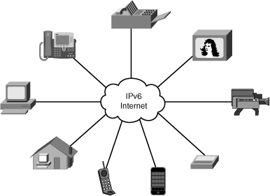
![]() Therefore, IPv6 has enough address space such that every user could have multiple global addresses that can be used for a wide variety of devices, such as wireless IP phones, entertainment set-top boxes, video equipment, security surveillance equipment, and so on, as illustrated in Figure 8-4. In the future other devices may be added, as technologies and requirements change. These device addresses would be reachable without using IP address translation, pooling, or temporary allocation techniques.
Therefore, IPv6 has enough address space such that every user could have multiple global addresses that can be used for a wide variety of devices, such as wireless IP phones, entertainment set-top boxes, video equipment, security surveillance equipment, and so on, as illustrated in Figure 8-4. In the future other devices may be added, as technologies and requirements change. These device addresses would be reachable without using IP address translation, pooling, or temporary allocation techniques.
![]() Note, however, that increasing the number of bits for the address also increases the IPv6 header size. Because each IP header contains a source address and a destination address, the size of the header fields that contains the addresses is 256 bits for IPv6 compared to 64 bits for IPv4. (The IPv6 header is described in detail in the “IPv6 Packet Header” section, earlier in this chapter.)
Note, however, that increasing the number of bits for the address also increases the IPv6 header size. Because each IP header contains a source address and a destination address, the size of the header fields that contains the addresses is 256 bits for IPv6 compared to 64 bits for IPv4. (The IPv6 header is described in detail in the “IPv6 Packet Header” section, earlier in this chapter.)
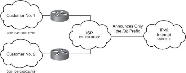
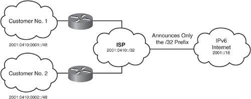
![]() IPv6’s larger address spaces allow for sizable address allocations to ISPs and organizations. An ISP can aggregate all the prefixes of its customers into a single prefix and announce the single prefix to the IPv6 Internet. Aggregation of customer prefixes results in an efficient and scalable routing table, which is necessary for broader adoption of network functions. The increased address space is also sufficient to allow organizations to define a single prefix for their entire network.
IPv6’s larger address spaces allow for sizable address allocations to ISPs and organizations. An ISP can aggregate all the prefixes of its customers into a single prefix and announce the single prefix to the IPv6 Internet. Aggregation of customer prefixes results in an efficient and scalable routing table, which is necessary for broader adoption of network functions. The increased address space is also sufficient to allow organizations to define a single prefix for their entire network.
 IPv6 Address Representation
![]() Rather than using dotted-decimal format, IPv6 addresses are written as hexadecimal numbers with colons between each set of four hexadecimal digits (which is 16 bits); we like to call this the “coloned hex” format. The format is x:x:x:x:x:x:x:x, where x is a 16-bit hexadecimal field; each x is therefore four hexadecimal digits. (Note that there are seven colons separating eight sections; each section has four hexadecimal digits.) An example address is as follows:
Rather than using dotted-decimal format, IPv6 addresses are written as hexadecimal numbers with colons between each set of four hexadecimal digits (which is 16 bits); we like to call this the “coloned hex” format. The format is x:x:x:x:x:x:x:x, where x is a 16-bit hexadecimal field; each x is therefore four hexadecimal digits. (Note that there are seven colons separating eight sections; each section has four hexadecimal digits.) An example address is as follows:
-
 2035:0001:2BC5:0000:0000:087C:0000:000A
| Note |
|
![]() Fortunately, you can shorten the written form of IPv6 addresses, in the following ways:
Fortunately, you can shorten the written form of IPv6 addresses, in the following ways:
-
 Leading 0s within each set of four hexadecimal digits can be omitted.
 -
 A pair of colons (::) can be used, only once within an address, to represent any number (“a bunch”) of successive 0s. An address parser identifies the number of missing 0s by separating the two parts of the address and entering 0s until it has 128 bits. If two (or more) :: notations were to be placed in the address, there would be no way to identify the size of each “bunch” of 0s.
![]() For example, the previous address can be shortened to the following:
For example, the previous address can be shortened to the following:
-
 2035:1:2BC5::87C:0:A
![]() Note that we used the :: only once within the address and we shortened the last set of 0000 to a single 0.
Note that we used the :: only once within the address and we shortened the last set of 0000 to a single 0.
![]() The following are some example IPv6 addresses and their shortened notation:
The following are some example IPv6 addresses and their shortened notation:
-
 The shortest IPv6 address is an all-0s address, 0:0:0:0:0:0:0:0 (which can be written as ::).
 -
 0:0:0:0:0:0:0:1 can be written as ::1.
 -
 2031:0000:130F:0000:0000:09C0:876A:130B can be written as 2031:0:130F::9C0:876A:130B. However, 2031::130F::9C0:876A:130B is not a valid address because it uses two sets of ::.
![]() Similar to how IPv4 subnet masks can be written as a prefix (for example, /24), IPv6 uses prefixes to indicate the number of bits of network or subnet. Prefix notation is also known as classless interdomain routing (CIDR) notation.
Similar to how IPv4 subnet masks can be written as a prefix (for example, /24), IPv6 uses prefixes to indicate the number of bits of network or subnet. Prefix notation is also known as classless interdomain routing (CIDR) notation.
![]() Of course, Cisco routers allow you to enter IPv6 addresses using the shortened format, and using the prefix. For example, Example 8-1 illustrates the configuration of the shortened IPv6 address discussed earlier, on a loopback interface. The prefix /64 is used on this interface. (Notice the similarity of the command to configure an IPv6 address to the command to configure an IPv4 address.)
Of course, Cisco routers allow you to enter IPv6 addresses using the shortened format, and using the prefix. For example, Example 8-1 illustrates the configuration of the shortened IPv6 address discussed earlier, on a loopback interface. The prefix /64 is used on this interface. (Notice the similarity of the command to configure an IPv6 address to the command to configure an IPv4 address.)
| Note |
|
R1(config)#interface loopback 100
R1(config-if)#ipv6 address 2035:1:2BC5::87C:0:A?
WORD  X:X:X:X::X  X:X:X:X::X/<0-128>
R1(config-if)#ipv6 address 2035:1:2BC5::87C:0:A/64
R1(config-if)#
 Interface Identifiers in IPv6 Addresses
![]() In IPv6, a link is defined as a network medium over which network nodes communicate using the link layer. Interface identifiers (IDs) in IPv6 addresses are used to identify a unique interface on a link. They may also be thought of as the “host portion” of an IPv6 address. Interface IDs are required to be unique on a link, and may also be unique over a broader scope. When the interface identifier is derived directly from the data link layer address of the interface, the scope of that identifier is assumed to be universal (global).
In IPv6, a link is defined as a network medium over which network nodes communicate using the link layer. Interface identifiers (IDs) in IPv6 addresses are used to identify a unique interface on a link. They may also be thought of as the “host portion” of an IPv6 address. Interface IDs are required to be unique on a link, and may also be unique over a broader scope. When the interface identifier is derived directly from the data link layer address of the interface, the scope of that identifier is assumed to be universal (global).
![]() Interface identifiers are always 64 bits and may be dynamically created based on Layer 2 media and encapsulation.
Interface identifiers are always 64 bits and may be dynamically created based on Layer 2 media and encapsulation.
![]() IPv6 is defined on most of the current data link layers, including those shown in Table 8-1.
IPv6 is defined on most of the current data link layers, including those shown in Table 8-1.
|
|
|
|
|
|
|
|
|
|
|
|
|
|
|
|
|
|
|
|
![]() The data link layer defines how IPv6 interface identifiers are created and how neighbor discovery deals with data link layer address resolution. RFCs describe the behavior of IPv6 in each of these specific data link layers, but the Cisco IOS Software does not necessarily support all of them.
The data link layer defines how IPv6 interface identifiers are created and how neighbor discovery deals with data link layer address resolution. RFCs describe the behavior of IPv6 in each of these specific data link layers, but the Cisco IOS Software does not necessarily support all of them.
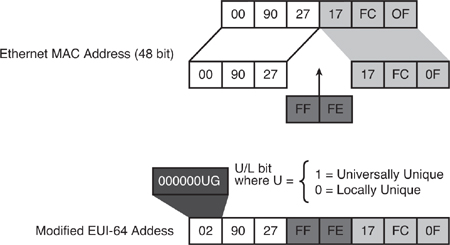
![]() For Ethernet, the interface ID used is based on the Media Access Control (MAC) address of the interface and is in an extended unique identifier 64-bit (EUI-64) format. The EUI-64 format interface ID is derived from the 48-bit link-layer MAC address by inserting the 16-bit hexadecimal number FFFE between the upper three bytes (the organizationally unique identifier [OUI] field) and the lower 3 bytes (the vendor code or serial number field) of the link-layer address. The seventh bit in the high-order byte is set to 1 to indicate the uniqueness of the interface ID.
For Ethernet, the interface ID used is based on the Media Access Control (MAC) address of the interface and is in an extended unique identifier 64-bit (EUI-64) format. The EUI-64 format interface ID is derived from the 48-bit link-layer MAC address by inserting the 16-bit hexadecimal number FFFE between the upper three bytes (the organizationally unique identifier [OUI] field) and the lower 3 bytes (the vendor code or serial number field) of the link-layer address. The seventh bit in the high-order byte is set to 1 to indicate the uniqueness of the interface ID.
![]() This process is illustrated in Figure 8-5.
This process is illustrated in Figure 8-5.
![]() The seventh bit in an IPv6 interface identifier is referred to as the Universal/Local (U/L) bit. This bit identifies whether this interface identifier is locally unique on the link or whether it is universally unique. When the interface identifier is created from an Ethernet MAC address, it is assumed that the MAC address is universally unique and, therefore, that the interface identifier is universally unique. The purpose of the U/L bit is for future use by upper-layer protocols to uniquely identify a connection, even in the context of a change in the far left part of the address. However, this feature is not yet used.
The seventh bit in an IPv6 interface identifier is referred to as the Universal/Local (U/L) bit. This bit identifies whether this interface identifier is locally unique on the link or whether it is universally unique. When the interface identifier is created from an Ethernet MAC address, it is assumed that the MAC address is universally unique and, therefore, that the interface identifier is universally unique. The purpose of the U/L bit is for future use by upper-layer protocols to uniquely identify a connection, even in the context of a change in the far left part of the address. However, this feature is not yet used.
![]() The eighth bit in an IPv6 interface identifier, also known as the G bit, is the group/individual bit for managing groups.
The eighth bit in an IPv6 interface identifier, also known as the G bit, is the group/individual bit for managing groups.
![]() Example 8-2 illustrates the configuration of a loopback interface, this time using the EUI-64 format for the interface ID by specifying the eui-64 keyword. After configuration, the interface is examined, and the highlighted line illustrates the resulting IPv6 address on the interface. Notice that the first part of the address is what we specified, and the last part is the EUI-64 interface ID. The subnet is the 64 bits that we specified.
Example 8-2 illustrates the configuration of a loopback interface, this time using the EUI-64 format for the interface ID by specifying the eui-64 keyword. After configuration, the interface is examined, and the highlighted line illustrates the resulting IPv6 address on the interface. Notice that the first part of the address is what we specified, and the last part is the EUI-64 interface ID. The subnet is the 64 bits that we specified.
R1(config)#interface loopback 100
R1(config-if)#ipv6 address 2001:8:85a3:4289::/64 ?
anycast Configure as an anycast
eui-64 Use eui-64 interface identifier
R1(config-if)#ipv6 address 2001:8:85a3:4289::/64 eui-64
![]() Because of privacy and security concerns, hosts may create a random interface identifier using the MAC address as a base. This is considered a privacy extension because, without it, creating an interface identifier from a MAC address allows activity to be tracked to the point of connection. For example, Microsoft Windows XP implements this capability and prefers to use this address for outgoing communication because the address has a short lifetime and will be regenerated periodically. This process is defined in RFC 4941, Privacy Extensions for Stateless Address Autoconfiguration in IPv6.
Because of privacy and security concerns, hosts may create a random interface identifier using the MAC address as a base. This is considered a privacy extension because, without it, creating an interface identifier from a MAC address allows activity to be tracked to the point of connection. For example, Microsoft Windows XP implements this capability and prefers to use this address for outgoing communication because the address has a short lifetime and will be regenerated periodically. This process is defined in RFC 4941, Privacy Extensions for Stateless Address Autoconfiguration in IPv6.
 IPv6 Address Types
![]() IPv6 has three main types of addresses. Unicast and multicast addresses are similar to their IPv4 companions. A new type of address, anycast, has also been introduced in IPv6. The following describe these IPv6 address types:
IPv6 has three main types of addresses. Unicast and multicast addresses are similar to their IPv4 companions. A new type of address, anycast, has also been introduced in IPv6. The following describe these IPv6 address types:
-
 Unicast— Similar to an IPv4 unicast address, an IPv6 unicast address is for a single interface. A packet that is sent to a unicast address goes to the interface identified by that address. As in IPv4, a subnet prefix in IPv6 is associated with one link. The IPv6 unicast address space encompasses the entire IPv6 address range, with the exception of the FF00::/8 range (addresses starting with binary 1111 1111), which is used for multicast addresses.
Note  An embedded IPv4 address is an IPv6 address that has the IPv4 address of the interface embedded within it. These addresses are described further in the “Tunneling IPv6 Traffic” section.
Note  There are multiple types of unicast addresses, including global aggregatable (which is also called global unicast), link-local, embedded IPv4, and site-local. (Note that site-local addresses are now deprecated.)
Note  RFC 4193, Unique Local IPv6 Unicast Addresses, defines another new type of unicast address with the FC00::/7 prefix that is globally unique and is intended for local communications. It is not covered further in this chapter.
 As described earlier, one difference between IPv4 and IPv6 unicast addresses is that the interface ID (the host portion of the address) can be automatically derived from the data link layer address for IPv6.
 -
 Multicast— An IPv6 multicast address identifies a set of interfaces on different devices. Just as in IPv4, a packet sent to a multicast address is delivered to all the interfaces identified by the multicast address. The range of multicast addresses in IPv6 is larger than in IPv4, and for the foreseeable future, allocation of IPv6 multicast groups is not being limited.
 -
 Anycast— An IPv6 anycast address is a new type of address that is assigned to a set of interfaces on different devices; an anycast address identifies multiple interfaces. A packet that is sent to an anycast address goes to the closest interface (as determined by the routing protocol being used) identified by the anycast address. Therefore, all nodes with the same anycast address should provide the same (uniform) service. Examples of when anycast addresses could be used are load balancing and content delivery services.
![]() Anycast addresses are syntactically indistinguishable from global unicast addresses because anycast addresses are allocated from the global unicast address space.
Anycast addresses are syntactically indistinguishable from global unicast addresses because anycast addresses are allocated from the global unicast address space.
![]() Anycast addresses must not be used as the source address of an IPv6 packet.
Anycast addresses must not be used as the source address of an IPv6 packet.
![]() In IPv4, broadcasting results in several problems, including generating interrupts in every computer on the network and, in some cases triggering malfunctions, known as broadcast storms, which can completely halt an entire network. It is important to notice that broadcasting does not exist in IPv6; broadcasts are replaced by multicasts and anycasts. Multicast enables efficient network operation by using specific multicast groups to send requests to a limited number of computers on the network. The multicast groups prevent most of the problems related to broadcast storms in IPv4.
In IPv4, broadcasting results in several problems, including generating interrupts in every computer on the network and, in some cases triggering malfunctions, known as broadcast storms, which can completely halt an entire network. It is important to notice that broadcasting does not exist in IPv6; broadcasts are replaced by multicasts and anycasts. Multicast enables efficient network operation by using specific multicast groups to send requests to a limited number of computers on the network. The multicast groups prevent most of the problems related to broadcast storms in IPv4.
![]() Note that a single interface may be assigned multiple IPv6 addresses of any type (unicast, anycast, and multicast). Every IPv6-enabled interface must contain at least one loopback (::1/128) and one link-local address. Optionally, an interface may have multiple unique local and global addresses.
Note that a single interface may be assigned multiple IPv6 addresses of any type (unicast, anycast, and multicast). Every IPv6-enabled interface must contain at least one loopback (::1/128) and one link-local address. Optionally, an interface may have multiple unique local and global addresses.
![]() The various address types are detailed in the following sections.
The various address types are detailed in the following sections.
 IPv6 Global Unicast Addresses
![]() The IPv6 addressing architecture is defined in RFC 4291, IP Version 6 Addressing Architecture.
The IPv6 addressing architecture is defined in RFC 4291, IP Version 6 Addressing Architecture.
![]() The IPv6 global aggregatable unicast address, also known as the IPv6 global unicast address, is the equivalent of the IPv4 global unicast address.
The IPv6 global aggregatable unicast address, also known as the IPv6 global unicast address, is the equivalent of the IPv4 global unicast address.
![]() A global unicast address is an IPv6 address from the global unicast prefix. The structure of global unicast addresses enables aggregation of routing prefixes so that the number of routing table entries in the global routing table can be reduced. Global unicast addresses used on links are aggregated upward through organizations and eventually to the ISPs, as illustrated in Figure 8-6. This provides for more efficient and scalable routing within the Internet, and improved bandwidth and functionality for user traffic.
A global unicast address is an IPv6 address from the global unicast prefix. The structure of global unicast addresses enables aggregation of routing prefixes so that the number of routing table entries in the global routing table can be reduced. Global unicast addresses used on links are aggregated upward through organizations and eventually to the ISPs, as illustrated in Figure 8-6. This provides for more efficient and scalable routing within the Internet, and improved bandwidth and functionality for user traffic.
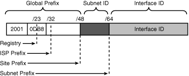
![]() The global unicast address typically consists of a 48-bit global routing prefix, a 16-bit subnet ID, and a 64-bit interface ID (typically in EUI-64 bit format), as illustrated in the example in Figure 8-7.
The global unicast address typically consists of a 48-bit global routing prefix, a 16-bit subnet ID, and a 64-bit interface ID (typically in EUI-64 bit format), as illustrated in the example in Figure 8-7.
![]() The subnet ID can be used by individual organizations to identify subnets and create their own local addressing hierarchy. This 16-bit field allows an organization to use up to 65,536 individual subnets.
The subnet ID can be used by individual organizations to identify subnets and create their own local addressing hierarchy. This 16-bit field allows an organization to use up to 65,536 individual subnets.
![]() Addresses with a prefix of 2000::/3 (binary 001) through E000::/3 (binary 111), excluding the FF00::/8 (binary 1111 1111) multicast addresses, are required to have 64-bit interface identifiers in the EUI-64 format.
Addresses with a prefix of 2000::/3 (binary 001) through E000::/3 (binary 111), excluding the FF00::/8 (binary 1111 1111) multicast addresses, are required to have 64-bit interface identifiers in the EUI-64 format.
![]() The current global unicast address assignment by the Internet Assigned Numbers Authority (IANA) uses the range of addresses that start with binary value 001. Another way to write this is 2000::/3, which means that they start with the same 3 bits as 2000; the 3 bits are 001. (Note that you have to write 16 bits, which is 4 hexadecimal digits, before the first colon.) This is one-eighth (12.5 percent) of the total IPv6 address space and is the largest block of assigned addresses.
The current global unicast address assignment by the Internet Assigned Numbers Authority (IANA) uses the range of addresses that start with binary value 001. Another way to write this is 2000::/3, which means that they start with the same 3 bits as 2000; the 3 bits are 001. (Note that you have to write 16 bits, which is 4 hexadecimal digits, before the first colon.) This is one-eighth (12.5 percent) of the total IPv6 address space and is the largest block of assigned addresses.
![]() The IANA is allocating the IPv6 address space in the ranges of 2001::/16 to the registries.
The IANA is allocating the IPv6 address space in the ranges of 2001::/16 to the registries.
 IPv6 Link-Local Unicast Addresses
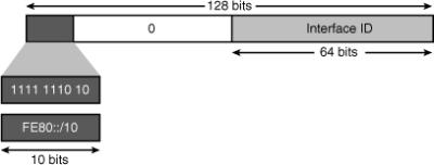
![]() Link-local addresses have a scope limited to the local link and are dynamically created on all IPv6 interfaces by using a specific link-local prefix FE80::/10 and a 64-bit interface identifier, as shown in Figure 8-8. Link-local addresses are used for automatic address configuration, neighbor discovery, router discovery, and by many routing protocols.
Link-local addresses have a scope limited to the local link and are dynamically created on all IPv6 interfaces by using a specific link-local prefix FE80::/10 and a 64-bit interface identifier, as shown in Figure 8-8. Link-local addresses are used for automatic address configuration, neighbor discovery, router discovery, and by many routing protocols.
![]() A link-local unicast address can serve as a method to connect devices on the same local network without requiring global addresses.
A link-local unicast address can serve as a method to connect devices on the same local network without requiring global addresses.
![]() When communicating with a link-local address, the outgoing interface must be specified because every interface is connected to FE80::/10. For example, if you want to ping from one router to its neighbor using the neighbor’s link-local address, you will be asked to input the interface on which you want to ping, because the router cannot determine the outgoing interface by looking at a link-local destination address.
When communicating with a link-local address, the outgoing interface must be specified because every interface is connected to FE80::/10. For example, if you want to ping from one router to its neighbor using the neighbor’s link-local address, you will be asked to input the interface on which you want to ping, because the router cannot determine the outgoing interface by looking at a link-local destination address.
![]() Example 8-3 repeats the show ipv6 interface output from the earlier Example 8-2, highlighting the automatically generated link-local address on the interface.
Example 8-3 repeats the show ipv6 interface output from the earlier Example 8-2, highlighting the automatically generated link-local address on the interface.
R1#show ipv6 interface loopback 100
Loopback100 is up, line protocol is up
 IPv6 is enabled, link-local address is FE80::21B:D5FF:FE5B:A408
 Global unicast address(es):
   2001:8:85A3:4289:21B:D5FF:FE5B:A408, subnet is 2001:8:85A3:4289::/64 [EUI]
 Joined group address(es):
   FF02::1
   FF02::2
   FF02::1:FF5B:A408
 MTU is 1514 bytes
 ICMP error messages limited to one every 100 milliseconds
 ICMP redirects are enabled
 ND DAD is not supported
 ND reachable time is 30000 milliseconds
 Hosts use stateless autoconfig for addresses.
R1#
 IPv6 Site-Local Unicast Addresses: Deprecated
![]() Site-local addresses were originally created to be similar to IPv4 private addresses. Note that this address type has since been deprecated (it is no longer supported). Because of the huge IPv6 address space, private addresses are not needed and using them would mean that NAT would be required and that addresses would again not be end-to-end. Site-local addresses are mentioned here only for legacy reasons.
Site-local addresses were originally created to be similar to IPv4 private addresses. Note that this address type has since been deprecated (it is no longer supported). Because of the huge IPv6 address space, private addresses are not needed and using them would mean that NAT would be required and that addresses would again not be end-to-end. Site-local addresses are mentioned here only for legacy reasons.
![]() As illustrated in Figure 8-9, site-local addresses were in the FEC0::/10 range, meaning they started with the same 10 bits as FEC0 (1111 1110 11).
As illustrated in Figure 8-9, site-local addresses were in the FEC0::/10 range, meaning they started with the same 10 bits as FEC0 (1111 1110 11).
 IPv6 Multicast Addresses
![]() A multicast address identifies a group of interfaces; traffic sent to a multicast address travels to multiple destinations at the same time. An interface may belong to any number of multicast groups. Multicasting is extremely important to IPv6, because it is at the core of many IPv6 functions and it is a replacement for broadcast.
A multicast address identifies a group of interfaces; traffic sent to a multicast address travels to multiple destinations at the same time. An interface may belong to any number of multicast groups. Multicasting is extremely important to IPv6, because it is at the core of many IPv6 functions and it is a replacement for broadcast.
![]() Multicast addresses are more efficient than broadcast addresses because traffic is sent only to the multicast recipients that have subscribed to the traffic. These recipients have joined the multicast group.
Multicast addresses are more efficient than broadcast addresses because traffic is sent only to the multicast recipients that have subscribed to the traffic. These recipients have joined the multicast group.
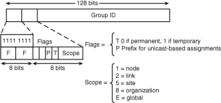
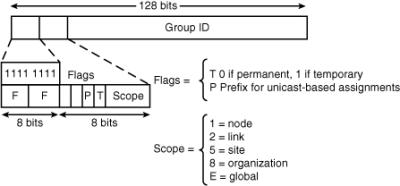
![]() The format of an IPv6 multicast address is illustrated in Figure 8-10. IPv6 multicast addresses are defined by the prefix FF00::/8. The second octet of the address contains the prefix and transient (lifetime) flags, and the scope of the multicast address, as follows:
The format of an IPv6 multicast address is illustrated in Figure 8-10. IPv6 multicast addresses are defined by the prefix FF00::/8. The second octet of the address contains the prefix and transient (lifetime) flags, and the scope of the multicast address, as follows:
-
 The transient (T) flag parameter is equal to 0 for a permanent, or well-known, multicast address. The flag is equal to 1 for a temporary (also known as a transient or dynamically assigned) multicast address.
 -
 The prefix (P) flag parameter indicates a prefix. This flag allows part of the multicast group address to include the unicast prefix of the source network.
 -
 The 4-bit scope parameter values include—1 for the node scope (for loopback transmission), 2 for the link scope (similar to unicast link-local scope), 5 for the site-local scope, 8 for the organizational scope (for multiple sites), and E for the global scope.
![]() For example, a multicast address starting with FF02::/16 is a permanent multicast address with a link-local scope. There is no TTL field in IPv6 multicast packets because the scoping is defined inside the address.
For example, a multicast address starting with FF02::/16 is a permanent multicast address with a link-local scope. There is no TTL field in IPv6 multicast packets because the scoping is defined inside the address.
![]() The multicast group ID consists of the lower 112 bits of the multicast address.
The multicast group ID consists of the lower 112 bits of the multicast address.
![]() The multicast addresses FF00:: to FF0F:: have the T flag set to 0 and are reserved. Within that range, the following are some example assigned addresses. (Many more assignments are made, and assignments are tracked by IANA.)
The multicast addresses FF00:: to FF0F:: have the T flag set to 0 and are reserved. Within that range, the following are some example assigned addresses. (Many more assignments are made, and assignments are tracked by IANA.)
-
 FF02::1—“All nodes” on a link (link-local scope).
Note  The FF02::1 multicast address is similar to a broadcast on a link.
 -
 FF02::2—“All routers” on a link.
 -
 FF02::9—“All routing information protocol (RIP) routers” on a link.
 -
 FF02::1:FFXX:XXXX—Solicited-node multicast on a link, where the XX:XXXX is the far right 24 bits of the corresponding unicast or anycast address of the node. Solicited-node multicast addresses are used in neighbor solicitation (NS) messages, which are sent on a local link when a node wants to determine the link-layer address of another node on the same local link, similar to the Address Resolution Protocol (ARP) in IPv4. The neighbor discovery (ND) process is described in the following section.
 -
 FF05::101—“All Network Time Protocol (NTP) servers” in the site (site-local scope). (The site-local multicast scope has an administratively assigned radius and has no direct correlation to the now deprecated site-local unicast prefix of FEC0::/10.)
 Solicited-Node Multicast Addresses
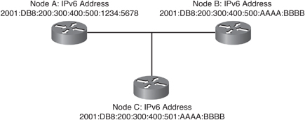
![]() Solicited-node multicast addresses are used in IPv6 during address resolution of an IPv6 address to a MAC address on a LAN segment. In rare cases, the far right 24 bits of the unicast address of the target will not be unique on a link, but this will not cause a problem, as illustrated by an example using the devices in Figure 8-11:
Solicited-node multicast addresses are used in IPv6 during address resolution of an IPv6 address to a MAC address on a LAN segment. In rare cases, the far right 24 bits of the unicast address of the target will not be unique on a link, but this will not cause a problem, as illustrated by an example using the devices in Figure 8-11:
-
 Node A has IPv6 address 2001:DB8:200:300:400:500:1234:5678.
 -
 Node B has IPv6 address 2001:DB8:200:300:400:500:AAAA:BBBB, and would therefore have solicited-node multicast address FF02:0:0:0:0:1:FFAA:BBBB, which can also be written as FF02::1:FFAA:BBBB.
 -
 Node C has IPv6 address 2001:DB8:200:300:400:501:AAAA:BBBB, and would therefore have solicited-node multicast address FF02::1:FFAA:BBBB. Note that this is the same as node B’s solicited-node multicast address.
![]() The neighbor discovery process uses these solicited-node multicast addresses. When node A desires to exchange packets with node B, node A sends an NS message to the solicited-node multicast address of node B, FF02::1:FFAA:BBBB. This message contains, in addition to other data, the full IPv6 address that node A is looking for, 2001:DB8:200:300:400:500:AAAA:BBBB. This is called the target address.
The neighbor discovery process uses these solicited-node multicast addresses. When node A desires to exchange packets with node B, node A sends an NS message to the solicited-node multicast address of node B, FF02::1:FFAA:BBBB. This message contains, in addition to other data, the full IPv6 address that node A is looking for, 2001:DB8:200:300:400:500:AAAA:BBBB. This is called the target address.
| Note |
|
![]() Both node B and node C are listening to the same solicited-node multicast address, so they both receive and process the packet. Node B sees that the target address inside the packet is its own and responds with a neighbor advertisement that includes its MAC address. Meanwhile, node C sees that the target address inside the packet is not its own and does not respond.
Both node B and node C are listening to the same solicited-node multicast address, so they both receive and process the packet. Node B sees that the target address inside the packet is its own and responds with a neighbor advertisement that includes its MAC address. Meanwhile, node C sees that the target address inside the packet is not its own and does not respond.
![]() In this manner, nodes can have the same solicited-node multicast address, but not cause the neighbor discovery process to malfunction.
In this manner, nodes can have the same solicited-node multicast address, but not cause the neighbor discovery process to malfunction.
| Note |
|
 IPv6 Anycast Addresses
![]() An IPv6 anycast address is a global unicast address that is assigned to more than one interface. The format is illustrated in Figure 8-12. For IPv6, anycast is defined as a way to send a packet to the nearest (or closest) interface that is a member of the anycast group, thus providing a discovery mechanism to the nearest point.
An IPv6 anycast address is a global unicast address that is assigned to more than one interface. The format is illustrated in Figure 8-12. For IPv6, anycast is defined as a way to send a packet to the nearest (or closest) interface that is a member of the anycast group, thus providing a discovery mechanism to the nearest point.
![]() A sender creates a packet with an anycast address as the destination address and forwards the packet to its nearest router. The router routes the packet to the nearest anycast interface (the closest device or interface that shares that address). For directly connected neighbors, the nearest interface is found according to the first neighbor that is learned about. Otherwise, the nearest interface is found according to the measure of the metric of the routing protocol.
A sender creates a packet with an anycast address as the destination address and forwards the packet to its nearest router. The router routes the packet to the nearest anycast interface (the closest device or interface that shares that address). For directly connected neighbors, the nearest interface is found according to the first neighbor that is learned about. Otherwise, the nearest interface is found according to the measure of the metric of the routing protocol.
![]() For example, interfaces on three servers may be assigned the same anycast address. A router receives a packet for this address; it determines which is closest, based on the metric of the routing protocol, and sends traffic to that closest recipient.
For example, interfaces on three servers may be assigned the same anycast address. A router receives a packet for this address; it determines which is closest, based on the metric of the routing protocol, and sends traffic to that closest recipient.
![]() Anycast addresses are allocated from the unicast address space and have the same format as unicast addresses, so they are indistinguishable from unicast addresses. To devices that are not configured for anycast, these addresses appear as unicast addresses. When a unicast address is assigned to more than one interface—thus turning it into an anycast address—the nodes to which the address is assigned must be explicitly configured to use and know that the address is an anycast address.
Anycast addresses are allocated from the unicast address space and have the same format as unicast addresses, so they are indistinguishable from unicast addresses. To devices that are not configured for anycast, these addresses appear as unicast addresses. When a unicast address is assigned to more than one interface—thus turning it into an anycast address—the nodes to which the address is assigned must be explicitly configured to use and know that the address is an anycast address.
| Note |
|
![]() The idea of anycast in IP was proposed in 1993. However, only a few IPv6 anycast addresses are currently assigned, including the router-subnet anycast and the Mobile IPv6 home agent anycast.
The idea of anycast in IP was proposed in 1993. However, only a few IPv6 anycast addresses are currently assigned, including the router-subnet anycast and the Mobile IPv6 home agent anycast.
![]() An anticipated use for anycast addresses is to control the paths across which traffic flows. An example use in a Border Gateway Protocol (BGP) multihomed network would be when a customer has multiple ISPs and multiple connections to each one. Each ISP could have a different anycast address. The same anycast address would be used for all routers of a given ISP. A customer device chooses which ISP to send the packet to; the routers along the path determine the closest router by which that ISP can be reached using the IPv6 anycast address.
An anticipated use for anycast addresses is to control the paths across which traffic flows. An example use in a Border Gateway Protocol (BGP) multihomed network would be when a customer has multiple ISPs and multiple connections to each one. Each ISP could have a different anycast address. The same anycast address would be used for all routers of a given ISP. A customer device chooses which ISP to send the packet to; the routers along the path determine the closest router by which that ISP can be reached using the IPv6 anycast address.
![]() Another use for an anycast address is when multiple routers are attached to a LAN. These routers can have the same IPv6 anycast address so that distant devices only need to identify the anycast address. Intermediate devices choose the best path to reach the closest entry point to that LAN.
Another use for an anycast address is when multiple routers are attached to a LAN. These routers can have the same IPv6 anycast address so that distant devices only need to identify the anycast address. Intermediate devices choose the best path to reach the closest entry point to that LAN.
 Comparing IPv6 Addresses with IPv4 Addresses
![]() Although there are many differences between IPv4 and IPv6, there are also many similarities, and you can leverage your IPv4 knowledge when learning and using IPv6.
Although there are many differences between IPv4 and IPv6, there are also many similarities, and you can leverage your IPv4 knowledge when learning and using IPv6.
![]() In earlier sections, you saw the format of IPv6 addresses. In devices, though, these addresses, like IPv4 addresses, are kept in binary. And like IPv4 addresses, IPv6 addresses can be summarized by finding the bits that addresses have in common.
In earlier sections, you saw the format of IPv6 addresses. In devices, though, these addresses, like IPv4 addresses, are kept in binary. And like IPv4 addresses, IPv6 addresses can be summarized by finding the bits that addresses have in common.
![]() For example, consider the following IPv4 addresses: 172.16.12.0/24, 172.16.13.0/24, 172.16.14.0/24, and 172.16.15.0/24. These addresses obviously have 172.16 in common, but they also have the first 6 bits of the third octet in common (000011). Therefore, the summary of these four routes is 172.16.12.0/22.
For example, consider the following IPv4 addresses: 172.16.12.0/24, 172.16.13.0/24, 172.16.14.0/24, and 172.16.15.0/24. These addresses obviously have 172.16 in common, but they also have the first 6 bits of the third octet in common (000011). Therefore, the summary of these four routes is 172.16.12.0/22.
![]() Similarly, IPv6 routes can be summarized. For example, let’s use the same addresses, but in IPv6 hexadecimal format. If we write out 172.16.12.0 in binary, we get the following:
Similarly, IPv6 routes can be summarized. For example, let’s use the same addresses, but in IPv6 hexadecimal format. If we write out 172.16.12.0 in binary, we get the following:
-
 10101100.00010000.00001100.00000000
![]() Converting this to hexadecimal, we get AC10:0C00. Therefore, we could use AC10:0C00::/24 as an IPv6 address. The other three addresses are AC10:0D00::/24, AC10:0E00::/24, and AC10:0F00::/24, respectively. The summary of these four addresses is AC10:0C00::/22, the same as we get for IPv4.
Converting this to hexadecimal, we get AC10:0C00. Therefore, we could use AC10:0C00::/24 as an IPv6 address. The other three addresses are AC10:0D00::/24, AC10:0E00::/24, and AC10:0F00::/24, respectively. The summary of these four addresses is AC10:0C00::/22, the same as we get for IPv4.
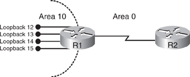
![]() To see this on Cisco routers, consider the simple network shown in Figure 8-13.
To see this on Cisco routers, consider the simple network shown in Figure 8-13.
![]() Example 8-4 shows the loopback interfaces’ IPv4 and IPv6 addresses configured on R1. Notice that the IPv6 addresses have the interface ID field set to 1 on each of the networks described in the summarization discussion. (Each loopback interface also has an automatically created link-local address.)
Example 8-4 shows the loopback interfaces’ IPv4 and IPv6 addresses configured on R1. Notice that the IPv6 addresses have the interface ID field set to 1 on each of the networks described in the summarization discussion. (Each loopback interface also has an automatically created link-local address.)
R1#show ip interface brief | begin Loop
Loopback12                 172.16.12.1     YES manual up                    up
Loopback13                 172.16.13.1     YES manual up                    up
Loopback14                 172.16.14.1     YES manual up                    up
Loopback15                 172.16.15.1     YES manual up                    up
Loopback100                unassigned      YES unset  up                    up
R1#

R1#show ipv6 interface brief | begin Loop
Loopback12                 [up/up]
   FE80::21B:D5FF:FE5B:A408
   AC10:C00::1
Loopback13                 [up/up]
   FE80::21B:D5FF:FE5B:A408
   AC10:D00::1
Loopback14                 [up/up]
   FE80::21B:D5FF:FE5B:A408
   AC10:E00::1
Loopback15                 [up/up]
   FE80::21B:D5FF:FE5B:A408
   AC10:F00::1
R1#
![]() The routers are running Open Shortest Path First Version 2 (OSPFv2) for IPv4 and OSPF Version 3 (OSPFv3) for IPv6. OSPFv3 and its associated configuration and verification commands are described in detail in the later “OSPFv3” section. For this discussion we need just the understanding of how OSPF works in general, as described for IPv4 in Chapter 3, “Configuring the Open Shortest Path First Protocol.”
The routers are running Open Shortest Path First Version 2 (OSPFv2) for IPv4 and OSPF Version 3 (OSPFv3) for IPv6. OSPFv3 and its associated configuration and verification commands are described in detail in the later “OSPFv3” section. For this discussion we need just the understanding of how OSPF works in general, as described for IPv4 in Chapter 3, “Configuring the Open Shortest Path First Protocol.”
![]() Example 8-5 illustrates the routing table on R2, for both IPv4 and IPv6. R2 sees all of R1’s IPv4 and IPv6 loopback interface addresses as interarea (O IA) routes.
Example 8-5 illustrates the routing table on R2, for both IPv4 and IPv6. R2 sees all of R1’s IPv4 and IPv6 loopback interface addresses as interarea (O IA) routes.
R2#show ip route ospf
    172.16.0.0/32 is subnetted, 4 subnets
O IA    172.16.13.1 [110/65] via 10.10.10.1, 00:01:49, Serial0/0/0
O IA    172.16.12.1 [110/65] via 10.10.10.1, 00:01:49, Serial0/0/0
O IA    172.16.15.1 [110/65] via 10.10.10.1, 00:01:49, Serial0/0/0
O IA    172.16.14.1 [110/65] via 10.10.10.1, 00:01:49, Serial0/0/0
R2#
R2#show ipv6 route ospf
IPv6 Routing Table - 6 entries
Codes: C - Connected, L - Local, S - Static, R - RIP, B - BGP
      U - Per-user Static route
      I1 - ISIS L1, I2 - ISIS L2, IA - ISIS interarea, IS - ISIS summary
      O - OSPF intra, OI - OSPF inter, OE1 - OSPF ext 1, OE2 - OSPF ext 2
      ON1 - OSPF NSSA ext 1, ON2 - OSPF NSSA ext 2
OI  AC10:C00::1/128 [110/64]
    via FE80::1, Serial0/0/0
OI  AC10:D00::1/128 [110/64]
    via FE80::1, Serial0/0/0
OI  AC10:E00::1/128 [110/64]
    via FE80::1, Serial0/0/0
OI  AC10:F00::1/128 [110/64]
    via FE80::1, Serial0/0/0
![]() To examine what happens when summarization is configured, the debug ip routing and debug ipv6 routing commands are entered on R2. The area 10 range 172.16.12.0 255.255.252.0 command is then configured on R1, to summarize the four IPv4 routes into 172.16.12.0/22. Example 8-6 illustrates the resulting debug messages on R2; the detailed routes are deleted and the summary route is added.
To examine what happens when summarization is configured, the debug ip routing and debug ipv6 routing commands are entered on R2. The area 10 range 172.16.12.0 255.255.252.0 command is then configured on R1, to summarize the four IPv4 routes into 172.16.12.0/22. Example 8-6 illustrates the resulting debug messages on R2; the detailed routes are deleted and the summary route is added.
| Caution |
|
R2:
*Dec 18 01:21:12.995: RT: del 172.16.15.1/32 via 10.10.10.1, ospf metric
[110/65]
*Dec 18 01:21:12.999: RT: delete subnet route to 172.16.15.1/32
*Dec 18 01:21:12.999: RT: NET-RED 172.16.15.1/32
*Dec 18 01:21:12.999: RT: del 172.16.14.1/32 via 10.10.10.1, ospf metric
[110/65]
*Dec 18 01:21:12.999: RT: delete subnet route to 172.16.14.1/32
*Dec 18 01:21:12.999: RT: NET-RED 172.16.14.1/32
*Dec 18 01:21:12.999: RT: del 172.16.13.1/32 via 10.10.10.1, ospf metric
[110/65]
*Dec 18 01:21:12.999: RT: delete subnet route to 172.16.13.1/32
*Dec 18 01:21:12.999: RT: NET-RED 172.16.13.1/32
*Dec 18 01:21:12.999: RT: del 172.16.12.1/32 via 10.10.10.1, ospf metric
[110/65]
*Dec 18 01:21:12.999: RT: delete subnet route to 172.16.12.1/32
*Dec 18 01:21:12.999: RT: NET-RED 172.16.12.1/32
*Dec 18 01:21:12.999: RT: delete network route to 172.16.0.0
*Dec 18 01:21:12.999: RT: NET-RED 172.16.0.0/16
*Dec 18 01:21:17.903: RT: SET_LAST_RDB for 172.16.12.0/22
 NEW rdb: via 10.10.10.1
*Dec 18 01:21:17.907: RT: add 172.16.12.0/22 via 10.10.10.1, ospf metric
[110/65]
*Dec 18 01:21:17.907: RT: NET-RED 172.16.12.0/22
![]() Example 8-7 illustrates the resulting routing table on R2; only the summary route is present.
Example 8-7 illustrates the resulting routing table on R2; only the summary route is present.
R2#show ip route ospf
    172.16.0.0/22 is subnetted, 1 subnet
O IA    172.16.12.0 [110/65] via 10.10.10.1, 00:00:32, Serial0/0/0
R2#
![]() Similarly, for IPv6, the area 10 range AC10:C00::/22 command is configured on R1, to summarize the four routes into AC10:0C00::/22. Example 8-8 illustrates the resulting debug messages on R2; the detailed routes are deleted and the summary route is added.
Similarly, for IPv6, the area 10 range AC10:C00::/22 command is configured on R1, to summarize the four routes into AC10:0C00::/22. Example 8-8 illustrates the resulting debug messages on R2; the detailed routes are deleted and the summary route is added.
R2:
*Dec 18 01:33:47.991: IPv6RT0: ospf 10, Route add AC10:C00::/22 [new]
*Dec 18 01:33:47.991: IPv6RT0: ospf 10, Add AC10:C00::/22 to table
*Dec 18 01:33:47.991: IPv6RT0: ospf 10, Adding next-hop FE80::1 over Serial0/0/0
for AC10:C00::/22, [110/64]
*Dec 18 01:33:47.991: IPv6RT0: ospf 10, Delete AC10:F00::1/128 from table
*Dec 18 01:33:47.991: IPv6RT0: ospf 10, Delete AC10:E00::1/128 from table
*Dec 18 01:33:47.991: IPv6RT0: ospf 10, Delete AC10:D00::1/128 from table
*Dec 18 01:33:47.991: IPv6RT0: ospf 10, Delete AC10:C00::1/128 from table
![]() Example 8-9 illustrates the resulting routing table on R2; only the summary route is present.
Example 8-9 illustrates the resulting routing table on R2; only the summary route is present.




0 comments
Post a Comment