Configuring BGP
![]() This section covers the commands used to configure some of the BGP features discussed in this chapter. After a discussion of planning a BGP implementation, the concept of peer groups is described first, because peer groups appear in many of the configuration commands.
This section covers the commands used to configure some of the BGP features discussed in this chapter. After a discussion of planning a BGP implementation, the concept of peer groups is described first, because peer groups appear in many of the configuration commands.
| Note |
|
 Planning BGP Implementations
![]() Before BGP configuration, a network administrator must define the network requirements including the internal connectivity (for IBGP) and the external connectivity to the ISP (for EBGP).
Before BGP configuration, a network administrator must define the network requirements including the internal connectivity (for IBGP) and the external connectivity to the ISP (for EBGP).
![]() The next step is to gather the parameters needed to provide the BGP configuration details. For basic BGP, these details include the following:
The next step is to gather the parameters needed to provide the BGP configuration details. For basic BGP, these details include the following:
-
 The autonomous system numbers (of your own network and of all remote autonomous systems)
 -
 The IP addresses of all the neighbors (peers) involved
 -
 The networks that are to be advertised into BGP
![]() Basic EBGP configuration requires the following main steps:
Basic EBGP configuration requires the following main steps:
-
 Define the BGP process
 -
 Establish the neighbor relationships
 -
 Advertise the networks into BGP
 Peer Groups
![]() In BGP, many neighbors are often configured with the same update policies (for example, they have the same filtering applied). On a Cisco IOS router, neighbors with the same update policies can be grouped into peer groups to simplify configuration and, more importantly, to make updating more efficient and improve performance. When a BGP router has many peers, this approach is highly recommended.
In BGP, many neighbors are often configured with the same update policies (for example, they have the same filtering applied). On a Cisco IOS router, neighbors with the same update policies can be grouped into peer groups to simplify configuration and, more importantly, to make updating more efficient and improve performance. When a BGP router has many peers, this approach is highly recommended.
![]() A BGP peer group is a group of BGP neighbors of the router being configured that all have the same update policies.
A BGP peer group is a group of BGP neighbors of the router being configured that all have the same update policies.
![]() Instead of separately defining the same policies for each neighbor, a peer group can be defined with these policies assigned to the peer group. Individual neighbors are then made members of the peer group. The policies of the peer group are similar to a template. The template is then applied to the individual members of the peer group.
Instead of separately defining the same policies for each neighbor, a peer group can be defined with these policies assigned to the peer group. Individual neighbors are then made members of the peer group. The policies of the peer group are similar to a template. The template is then applied to the individual members of the peer group.
![]() Members of the peer group inherit all the peer group’s configuration options. The router can also be configured to override these options for some members of the peer group if these options do not affect outbound updates. In other words, only options that affect the inbound updates can be overridden.
Members of the peer group inherit all the peer group’s configuration options. The router can also be configured to override these options for some members of the peer group if these options do not affect outbound updates. In other words, only options that affect the inbound updates can be overridden.
![]() Peer groups are more efficient than defining the same policies for each neighbor, because updates are generated only once per peer group rather than repetitiously for each neighboring router. The generated update is replicated for each neighbor that is part of the peer group.
Peer groups are more efficient than defining the same policies for each neighbor, because updates are generated only once per peer group rather than repetitiously for each neighboring router. The generated update is replicated for each neighbor that is part of the peer group.
![]() Thus, peer groups save processing time in generating the updates for all IBGP neighbors and make the router configuration easier to read and manage.
Thus, peer groups save processing time in generating the updates for all IBGP neighbors and make the router configuration easier to read and manage.
![]() The neighbor peer-group-name peer-group router configuration command is used to create a BGP peer group. The peer-group-name is the name of the BGP peer group to be created. The peer-group-name is local to the router on which it is configured; it is not passed to any other router.
The neighbor peer-group-name peer-group router configuration command is used to create a BGP peer group. The peer-group-name is the name of the BGP peer group to be created. The peer-group-name is local to the router on which it is configured; it is not passed to any other router.
![]() Another syntax form of the neighbor peer-group command, the neighbor ip-address peer-group peer-group-name router configuration command, is used to assign neighbors as part of the group after the group has been created. Table 6-3 provides details of the parameters of this command. Using this command allows you to type the peer group name instead of typing the IP addresses of individual neighbors in other commands (for example, to link a policy to the group of neighboring routers). (Note that you must enter the neighbor peer-group-name peer-group command before the router will accept this second command.)
Another syntax form of the neighbor peer-group command, the neighbor ip-address peer-group peer-group-name router configuration command, is used to assign neighbors as part of the group after the group has been created. Table 6-3 provides details of the parameters of this command. Using this command allows you to type the peer group name instead of typing the IP addresses of individual neighbors in other commands (for example, to link a policy to the group of neighboring routers). (Note that you must enter the neighbor peer-group-name peer-group command before the router will accept this second command.)
|
|
|
|---|---|
|
|
|
|
|
|
![]() A neighboring router can be part of only one peer group.
A neighboring router can be part of only one peer group.
| Note |
|
![]() The clear ip bgp peer-group peer-group-name EXEC command is used to reset the BGP connections for all members of a BGP peer group. The peer-group-name is the name of the BGP peer group for which connections are to be cleared.
The clear ip bgp peer-group peer-group-name EXEC command is used to reset the BGP connections for all members of a BGP peer group. The peer-group-name is the name of the BGP peer group for which connections are to be cleared.
| Caution |
|
 Entering BGP Configuration Mode
![]() Use the router bgp autonomous-system global configuration command to enter BGP configuration mode, and identify the local autonomous system in which this router belongs. In the command, autonomous-system identifies the local autonomous system. The BGP process needs to be informed of its autonomous system so that when BGP neighbors are configured it can determine whether they are IBGP or EBGP neighbors.
Use the router bgp autonomous-system global configuration command to enter BGP configuration mode, and identify the local autonomous system in which this router belongs. In the command, autonomous-system identifies the local autonomous system. The BGP process needs to be informed of its autonomous system so that when BGP neighbors are configured it can determine whether they are IBGP or EBGP neighbors.
![]() The router bgp command alone does not activate BGP on a router. You must enter at least one subcommand under the router bgp command to activate the BGP process on the router.
The router bgp command alone does not activate BGP on a router. You must enter at least one subcommand under the router bgp command to activate the BGP process on the router.
![]() Only one instance of BGP can be configured on a router at a time. For example, if you configure your router in autonomous system 65000 and then try to configure the router bgp 65100 command, the router informs you that you are currently configured for autonomous system 65000.
Only one instance of BGP can be configured on a router at a time. For example, if you configure your router in autonomous system 65000 and then try to configure the router bgp 65100 command, the router informs you that you are currently configured for autonomous system 65000.
 Defining BGP Neighbors and Activating BGP Sessions
![]() Use the neighbor {ip-address | peer-group-name} remote-as autonomous-system router configuration command to activate a BGP session for external and internal neighbors and to identify a peer router with which the local router will establish a session, as described in Table 6-4.
Use the neighbor {ip-address | peer-group-name} remote-as autonomous-system router configuration command to activate a BGP session for external and internal neighbors and to identify a peer router with which the local router will establish a session, as described in Table 6-4.
|
|
|
|---|---|
|
|
|
|
|
|
|
|
|
![]() The IP address used in the neighbor remote-as command is the destination address for all BGP packets going to this neighboring router. For a BGP relationship to be established, this address must be reachable, because BGP attempts to establish a TCP session and exchange BGP updates with the device at this IP address.
The IP address used in the neighbor remote-as command is the destination address for all BGP packets going to this neighboring router. For a BGP relationship to be established, this address must be reachable, because BGP attempts to establish a TCP session and exchange BGP updates with the device at this IP address.
![]() The value placed in the autonomous-system field of the neighbor remote-as command determines whether the communication with the neighbor is an EBGP or IBGP session. If the autonomous-system field configured in the router bgp command is identical to the field in the neighbor remote-as command, BGP initiates an internal session, and the IP address specified does not have to be directly connected. If the field values are different, BGP initates an external session, and the IP address specified must be directly connected, by default.
The value placed in the autonomous-system field of the neighbor remote-as command determines whether the communication with the neighbor is an EBGP or IBGP session. If the autonomous-system field configured in the router bgp command is identical to the field in the neighbor remote-as command, BGP initiates an internal session, and the IP address specified does not have to be directly connected. If the field values are different, BGP initates an external session, and the IP address specified must be directly connected, by default.
![]() The network shown in Figure 6-34 uses the BGP neighbor commands. The configurations of Routers A, B, and C are shown in Examples 6-2, 6-3, and 6-4. Router A in autonomous system 65101 has two neighbor statements. In the first statement, neighbor 10.2.2.2 (Router B) is in the same autonomous system as Router A (65101); this neighbor statement defines Router B as an IBGP neighbor. autonomous system 65101 runs EIGRP between all internal routers. Router A has an EIGRP path to reach IP address 10.2.2.2. As an IBGP neighbor, Router B can be multiple routers away from Router A.
The network shown in Figure 6-34 uses the BGP neighbor commands. The configurations of Routers A, B, and C are shown in Examples 6-2, 6-3, and 6-4. Router A in autonomous system 65101 has two neighbor statements. In the first statement, neighbor 10.2.2.2 (Router B) is in the same autonomous system as Router A (65101); this neighbor statement defines Router B as an IBGP neighbor. autonomous system 65101 runs EIGRP between all internal routers. Router A has an EIGRP path to reach IP address 10.2.2.2. As an IBGP neighbor, Router B can be multiple routers away from Router A.
router bgp 65101
 neighbor 10.2.2.2 remote-as 65101
 neighbor 192.168.1.1 remote-as 65102
router bgp 65101
 neighbor 10.1.1.2 remote-as 65101
router bgp 65102
 neighbor 192.168.1.2 remote-as 65101
![]() Router A in Figure 6-34 knows that Router C is an external neighbor because the neighbor statement for Router C uses autonomous system 65102, which is different from the autonomous system number of Router A, autonomous system 65101. Router A can reach autonomous system 65102 via 192.168.1.1, which is directly connected to Router A.
Router A in Figure 6-34 knows that Router C is an external neighbor because the neighbor statement for Router C uses autonomous system 65102, which is different from the autonomous system number of Router A, autonomous system 65101. Router A can reach autonomous system 65102 via 192.168.1.1, which is directly connected to Router A.
| Note |
|
 Shutting Down a BGP Neighbor
![]() To disable (administratively shut down) an existing BGP neighbor or peer group, use the neighbor {ip-address | peer-group-name} shutdown router configuration command. To enable a previously existing neighbor or peer group that had been disabled using the neighbor shutdown command, use the no neighbor {ip-address | peer-group-name} shutdown router configuration command. If you want to implement major policy changes to a neighboring router and you change multiple parameters, you must administratively shut down the neighboring router, implement the changes, and then bring the neighboring router back up.
To disable (administratively shut down) an existing BGP neighbor or peer group, use the neighbor {ip-address | peer-group-name} shutdown router configuration command. To enable a previously existing neighbor or peer group that had been disabled using the neighbor shutdown command, use the no neighbor {ip-address | peer-group-name} shutdown router configuration command. If you want to implement major policy changes to a neighboring router and you change multiple parameters, you must administratively shut down the neighboring router, implement the changes, and then bring the neighboring router back up.
![]() Using the neighbor shutdown command not only terminates the session, but also removes all associated routing information.
Using the neighbor shutdown command not only terminates the session, but also removes all associated routing information.
 Defining the Source IP Address
![]() The BGP neighbor statement tells the BGP process the destination IP address of each update packet. The router must decide which IP address to use as the source IP address in the BGP routing update.
The BGP neighbor statement tells the BGP process the destination IP address of each update packet. The router must decide which IP address to use as the source IP address in the BGP routing update.
![]() When a router creates a packet, whether it is a routing update, a ping, or any other type of IP packet, the router does a lookup in the routing table for the destination address. The routing table lists the appropriate interface to get to the destination address. The address of this outbound interface is used as that packet’s source address by default.
When a router creates a packet, whether it is a routing update, a ping, or any other type of IP packet, the router does a lookup in the routing table for the destination address. The routing table lists the appropriate interface to get to the destination address. The address of this outbound interface is used as that packet’s source address by default.
![]() For BGP packets, this source IP address must match the address in the corresponding neighbor statement on the other router. (In other words, the other router must have a BGP relationship with the packet’s source IP address.) Otherwise, the routers will not be able to establish the BGP session, and the packet will be ignored. BGP does not accept unsolicited updates; it must be aware of every neighboring router and have a neighbor statement for it.
For BGP packets, this source IP address must match the address in the corresponding neighbor statement on the other router. (In other words, the other router must have a BGP relationship with the packet’s source IP address.) Otherwise, the routers will not be able to establish the BGP session, and the packet will be ignored. BGP does not accept unsolicited updates; it must be aware of every neighboring router and have a neighbor statement for it.
![]() For example, in Figure 6-35, assume that Router D uses the neighbor 10.3.3.1 remote-as 65102 command to establish a relationship with Router A. If Router A sends the BGP packets to Router D via Router B, the source IP address of the packets is 10.1.1.1. When Router D receives a BGP packet from 10.1.1.1, it does not recognize the sender of the BGP packet, because 10.1.1.1 is not configured as a neighbor of Router D. Therefore, the IBGP session between Router A and Router D is not be established.
For example, in Figure 6-35, assume that Router D uses the neighbor 10.3.3.1 remote-as 65102 command to establish a relationship with Router A. If Router A sends the BGP packets to Router D via Router B, the source IP address of the packets is 10.1.1.1. When Router D receives a BGP packet from 10.1.1.1, it does not recognize the sender of the BGP packet, because 10.1.1.1 is not configured as a neighbor of Router D. Therefore, the IBGP session between Router A and Router D is not be established.
![]() A solution to this problem is to establish the IBGP session using a loopback interface when multiple paths exist between the IBGP neighbors.
A solution to this problem is to establish the IBGP session using a loopback interface when multiple paths exist between the IBGP neighbors.
![]() If the IP address of a loopback interface is used in the neighbor command, some extra configuration must be done on the neighbor router. You must tell BGP to use a loopback interface address rather than a physical interface address as the source address for all BGP packets, including those that initiate the BGP neighbor TCP connection. Use the neighbor {ip-address | peer-group-name} update-source loopback interface-number router configuration command to cause the router to use the address of the specified loopback interface as the source address for BGP connections to this neighbor.
If the IP address of a loopback interface is used in the neighbor command, some extra configuration must be done on the neighbor router. You must tell BGP to use a loopback interface address rather than a physical interface address as the source address for all BGP packets, including those that initiate the BGP neighbor TCP connection. Use the neighbor {ip-address | peer-group-name} update-source loopback interface-number router configuration command to cause the router to use the address of the specified loopback interface as the source address for BGP connections to this neighbor.
![]() The update-source option in the neighbor command overrides the default source IP address selection for BGP packets. This peering arrangement also adds resiliency to the IBGP sessions because they are not tied into a physical interface, which might go down for any number of reasons. For example, if a BGP router is using a neighbor address that is assigned to a specific physical interface on another router, and that interface goes down, the router pointing to that address loses its BGP session with its BGP neighbor. If, instead, the router peers with the loopback interface of the other router, the BGP session is not lost, because the loopback interface is always available as long as the router itself does not fail.
The update-source option in the neighbor command overrides the default source IP address selection for BGP packets. This peering arrangement also adds resiliency to the IBGP sessions because they are not tied into a physical interface, which might go down for any number of reasons. For example, if a BGP router is using a neighbor address that is assigned to a specific physical interface on another router, and that interface goes down, the router pointing to that address loses its BGP session with its BGP neighbor. If, instead, the router peers with the loopback interface of the other router, the BGP session is not lost, because the loopback interface is always available as long as the router itself does not fail.
![]() To peer with the loopback interface of an IBGP neighbor, configure each router with a neighbor command using the neighbor’s loopback address. Both routers must have a route to the loopback address of the other neighbor in their routing table; check to ensure that both routers are announcing their loopback addresses into the IGP. The neighbor update-source command is also necessary for both routers.
To peer with the loopback interface of an IBGP neighbor, configure each router with a neighbor command using the neighbor’s loopback address. Both routers must have a route to the loopback address of the other neighbor in their routing table; check to ensure that both routers are announcing their loopback addresses into the IGP. The neighbor update-source command is also necessary for both routers.
![]() For example, in Figure 6-36, Router B has Router A as an EBGP neighbor and Router C as an IBGP neighbor. The configurations for Routers B and C are shown in Examples 6-5 and 6-6. The only reachable address that Router B can use to establish a BGP neighbor relationship with Router A is the directly connected address 172.16.1.1. However, Router B has multiple paths to reach Router C, an IBGP neighbor. All networks, including the IP network for Router C’s loopback interface, can be reached from Router B because these two routers exchange EIGRP updates. (Router B and Router A do not exchange EIGRP updates.) The neighbor relationship between Routers B and C is not tied to a physical interface, because each router peers with the loopback interface on the other router and uses its loopback address as the BGP source IP address. If Router B instead peered with 10.1.1.2 on Router C and that interface went down, the BGP neighbor relationship would be lost.
For example, in Figure 6-36, Router B has Router A as an EBGP neighbor and Router C as an IBGP neighbor. The configurations for Routers B and C are shown in Examples 6-5 and 6-6. The only reachable address that Router B can use to establish a BGP neighbor relationship with Router A is the directly connected address 172.16.1.1. However, Router B has multiple paths to reach Router C, an IBGP neighbor. All networks, including the IP network for Router C’s loopback interface, can be reached from Router B because these two routers exchange EIGRP updates. (Router B and Router A do not exchange EIGRP updates.) The neighbor relationship between Routers B and C is not tied to a physical interface, because each router peers with the loopback interface on the other router and uses its loopback address as the BGP source IP address. If Router B instead peered with 10.1.1.2 on Router C and that interface went down, the BGP neighbor relationship would be lost.
router bgp 65101
 neighbor 172.16.1.1 remote-as 65100
 neighbor 192.168.3.3 remote-as 65101
 neighbor 192.168.3.3 update-source loopback0
!

router eigrp 1
 network 10.0.0.0
 network 192.168.2.0
router bgp 65101
 neighbor 192.168.1.1 remote-as 65102
 neighbor 192.168.2.2 remote-as 65101
 neighbor 192.168.2.2 update-source loopback0
!

router eigrp 1
 network 10.0.0.0
 network 192.168.3.0
![]() If Router B points at loopback address 192.168.3.3 on Router C and Router C points at loopback address 192.168.2.2 on Router B, but neither uses the neighbor update-source command, a BGP session is not established between these routers. Without this command, Router B will send a BGP open packet to Router C with a source IP address of either 10.1.1.1 or 10.2.2.1. Router C will examine the source IP address and attempt to match it against its list of known neighbors. Because Router C will not find a match, it will not respond to the open message from Router B.
If Router B points at loopback address 192.168.3.3 on Router C and Router C points at loopback address 192.168.2.2 on Router B, but neither uses the neighbor update-source command, a BGP session is not established between these routers. Without this command, Router B will send a BGP open packet to Router C with a source IP address of either 10.1.1.1 or 10.2.2.1. Router C will examine the source IP address and attempt to match it against its list of known neighbors. Because Router C will not find a match, it will not respond to the open message from Router B.
 EBGP Multihop
![]() When peering with an external neighbor, the only address that an EBGP router can reach without further configuration is the interface that is directly connected to that EBGP router. Because IGP routing information is not exchanged with external peers, the router must by default point to a directly connected address for external neighbors. A loopback interface is never directly connected. Therefore, if you want to peer with a loopback interface instead, you have to add a static route to the loopback pointing to the physical address of the directly connected network (the next-hop address). You must also enable multihop EBGP, with the neighbor {ip-address | peer-group-name} ebgp-multihop [ttl] router configuration command.
When peering with an external neighbor, the only address that an EBGP router can reach without further configuration is the interface that is directly connected to that EBGP router. Because IGP routing information is not exchanged with external peers, the router must by default point to a directly connected address for external neighbors. A loopback interface is never directly connected. Therefore, if you want to peer with a loopback interface instead, you have to add a static route to the loopback pointing to the physical address of the directly connected network (the next-hop address). You must also enable multihop EBGP, with the neighbor {ip-address | peer-group-name} ebgp-multihop [ttl] router configuration command.
![]() This command allows the router to accept and attempt BGP connections to external peers residing on networks that are not directly connected. This command increases the default of one hop for EBGP peers by changing the default Time To Live (TTL) value of 1 (with the ttl parameter) and therefore allowing routes to the EBGP loopback address. By default, the TTL is set to 255 with this command. This command is useful when redundant paths exist between EBGP neighbors.
This command allows the router to accept and attempt BGP connections to external peers residing on networks that are not directly connected. This command increases the default of one hop for EBGP peers by changing the default Time To Live (TTL) value of 1 (with the ttl parameter) and therefore allowing routes to the EBGP loopback address. By default, the TTL is set to 255 with this command. This command is useful when redundant paths exist between EBGP neighbors.
![]() For example, in Figure 6-37, Router A in autonomous system 65102 has two paths to Router B in autonomous system 65101. If Router A uses a single neighbor statement that points to 192.168.1.18 on Router B and that link goes down, the BGP session between these autonomous systems is lost, and no packets pass from one autonomous system to the next, even though another link exists. This problem can be solved if Router A uses two neighbor statements pointing to 192.168.1.18 and 192.168.1.34 on Router B. However, every BGP update that Router A receives will be sent to Router B twice because of the two neighbor statements.
For example, in Figure 6-37, Router A in autonomous system 65102 has two paths to Router B in autonomous system 65101. If Router A uses a single neighbor statement that points to 192.168.1.18 on Router B and that link goes down, the BGP session between these autonomous systems is lost, and no packets pass from one autonomous system to the next, even though another link exists. This problem can be solved if Router A uses two neighbor statements pointing to 192.168.1.18 and 192.168.1.34 on Router B. However, every BGP update that Router A receives will be sent to Router B twice because of the two neighbor statements.
![]() The configurations of Routers A and B are shown in Examples 6-7 and 6-8. As these configurations show, each router instead points to the loopback address of the other router and uses its loopback address as the source IP address for its BGP updates. Because an IGP is not used between autonomous systems, neither router can reach the loopback of the other router without assistance. Each router needs to use two static routes to define the paths available to reach the loopback address of the other router. The neighbor ebgp-multihop command must also be configured to change the default setting of BGP and inform the BGP process that this neighbor IP address is more than one hop away. In these examples, the commands used on Routers A and B inform BGP that the neighbor address is two hops away (one hop to the other router and one hop through the router to the loopback interface).
The configurations of Routers A and B are shown in Examples 6-7 and 6-8. As these configurations show, each router instead points to the loopback address of the other router and uses its loopback address as the source IP address for its BGP updates. Because an IGP is not used between autonomous systems, neither router can reach the loopback of the other router without assistance. Each router needs to use two static routes to define the paths available to reach the loopback address of the other router. The neighbor ebgp-multihop command must also be configured to change the default setting of BGP and inform the BGP process that this neighbor IP address is more than one hop away. In these examples, the commands used on Routers A and B inform BGP that the neighbor address is two hops away (one hop to the other router and one hop through the router to the loopback interface).
router bgp 65102
 neighbor 172.16.1.1 remote-as 65101
 neighbor 172.16.1.1 update-source loopback0
 neighbor 172.16.1.1 ebgp-multihop 2
ip route 172.16.1.1 255.255.255.255 192.168.1.18
ip route 172.16.1.1 255.255.255.255 192.168.1.34
router bgp 65101
 neighbor 172.17.1.1 remote-as 65102
 neighbor 172.17.1.1 update-source loopback0
 neighbor 172.17.1.1 ebgp-multihop 2
ip route 172.17.1.1 255.255.255.255 192.168.1.17
ip route 172.17.1.1 255.255.255.255 192.168.1.33
 Changing the Next-Hop Attribute
![]() As discussed in the section “The Next-Hop Attribute,” earlier in this chapter, it is sometimes necessary (for example, in an NBMA environment) to override a router’s default behavior and force it to advertise itself as the next-hop address for routes sent to a neighbor.
As discussed in the section “The Next-Hop Attribute,” earlier in this chapter, it is sometimes necessary (for example, in an NBMA environment) to override a router’s default behavior and force it to advertise itself as the next-hop address for routes sent to a neighbor.
![]() An internal protocol, such as RIP, EIGRP, or OSPF, always uses the source IP address of a routing update as the next-hop address for each network from that update that is placed in the routing table. The neighbor {ip-address | peer-group-name} next-hop-self router configuration command is used to force BGP to use the source IP address of the update as the next hop for each network it advertises to the neighbor, rather than letting the protocol choose the next-hop address to use. This command is described in Table 6-5.
An internal protocol, such as RIP, EIGRP, or OSPF, always uses the source IP address of a routing update as the next-hop address for each network from that update that is placed in the routing table. The neighbor {ip-address | peer-group-name} next-hop-self router configuration command is used to force BGP to use the source IP address of the update as the next hop for each network it advertises to the neighbor, rather than letting the protocol choose the next-hop address to use. This command is described in Table 6-5.
|
|
|
|---|---|
|
|
|
|
|
|
![]() For example, in Figure 6-38, Router B views all routes learned from autonomous system 65100 as having a next hop of 172.16.1.1, which is the entrance to autonomous system 65100 for Router B. When Router B announces those networks to its IBGP neighbors in autonomous system 65101, the BGP default setting is to announce that the next hop to reach each of those networks is the entrance to autonomous system 65100 (172.16.1.1), because BGP is an autonomous system-by-autonomous system routing protocol. With the default settings, a BGP router needs to reach the 172.16.1.1 next hop to reach networks in or behind autonomous system 65100. Therefore, the network that represents 172.16.1.1 will have to be advertised in the internal routing protocol.
For example, in Figure 6-38, Router B views all routes learned from autonomous system 65100 as having a next hop of 172.16.1.1, which is the entrance to autonomous system 65100 for Router B. When Router B announces those networks to its IBGP neighbors in autonomous system 65101, the BGP default setting is to announce that the next hop to reach each of those networks is the entrance to autonomous system 65100 (172.16.1.1), because BGP is an autonomous system-by-autonomous system routing protocol. With the default settings, a BGP router needs to reach the 172.16.1.1 next hop to reach networks in or behind autonomous system 65100. Therefore, the network that represents 172.16.1.1 will have to be advertised in the internal routing protocol.
![]() In this example, however, the configuration for Router B is as shown in Example 6-9. Router B uses the neighbor next-hop-self command to change the default BGP next-hop settings. After this command is configured, Router B advertises a next hop of 192.168.2.2 (the IP address of its loopback interface) to its IBGP neighbor because that is the source IP address of the routing update to its IBGP neighbor (set with the neighbor update-source command).
In this example, however, the configuration for Router B is as shown in Example 6-9. Router B uses the neighbor next-hop-self command to change the default BGP next-hop settings. After this command is configured, Router B advertises a next hop of 192.168.2.2 (the IP address of its loopback interface) to its IBGP neighbor because that is the source IP address of the routing update to its IBGP neighbor (set with the neighbor update-source command).
router bgp 65101
 neighbor 172.16.1.1 remote-as 65100
 neighbor 192.168.3.3 remote-as 65101
 neighbor 192.168.3.3 update-source loopback0
 neighbor 192.168.3.3 next-hop-self
!

router eigrp 1
 network 10.0.0.0
 network 192.168.2.0
![]() When Router C announces networks that are in or behind autonomous system 65101 to its EBGP neighbors, such as Router D in autonomous system 65102, Router C, by default, uses its outbound interface address 192.168.1.2 as the next-hop address. This address is the default next-hop address for Router D to use to reach any networks in or behind autonomous system 65101.
When Router C announces networks that are in or behind autonomous system 65101 to its EBGP neighbors, such as Router D in autonomous system 65102, Router C, by default, uses its outbound interface address 192.168.1.2 as the next-hop address. This address is the default next-hop address for Router D to use to reach any networks in or behind autonomous system 65101.
 Defining the Networks That BGP Advertises
![]() Two options are available to advertise networks into BGP: using the network command, and redistributing routes from an IGP into BGP. Redistribution is described in Chapter 4. The network command is described in the next section.
Two options are available to advertise networks into BGP: using the network command, and redistributing routes from an IGP into BGP. Redistribution is described in Chapter 4. The network command is described in the next section.
| Note |
|
![]() Use the network network-number [mask network-mask] [route-map map-tag] router configuration command to permit BGP to advertise a network if it is present in the IP routing table, as described in Table 6-6.
Use the network network-number [mask network-mask] [route-map map-tag] router configuration command to permit BGP to advertise a network if it is present in the IP routing table, as described in Table 6-6.
|
|
|
|---|---|
|
|
|
|
|
|
|
|
|
![]() It is important to note that the BGP network command determines which networks this router advertises. This is a different concept from what you are used to when configuring IGPs. Unlike for IGPs, the network command does not start BGP on specific interfaces. Rather, it indicates to BGP which networks it should originate from this router. The mask parameter indicates that BGP-4 can handle subnetting and supernetting. The list of network commands must include all networks in your autonomous system that you want to advertise, not just those locally connected to your router.
It is important to note that the BGP network command determines which networks this router advertises. This is a different concept from what you are used to when configuring IGPs. Unlike for IGPs, the network command does not start BGP on specific interfaces. Rather, it indicates to BGP which networks it should originate from this router. The mask parameter indicates that BGP-4 can handle subnetting and supernetting. The list of network commands must include all networks in your autonomous system that you want to advertise, not just those locally connected to your router.
![]() The network command allows classless prefixes; the router can advertise individual subnets, networks, or supernets. It is also important to note that the prefix must exactly match (address and mask) an entry in the IP routing table. A static route to null 0 might be used to create a supernet entry in the IP routing table.
The network command allows classless prefixes; the router can advertise individual subnets, networks, or supernets. It is also important to note that the prefix must exactly match (address and mask) an entry in the IP routing table. A static route to null 0 might be used to create a supernet entry in the IP routing table.
![]() Notice the difference between the neighbor command and the network command: The neighbor command tells BGP where to advertise. The network command tells BGP what to advertise.
Notice the difference between the neighbor command and the network command: The neighbor command tells BGP where to advertise. The network command tells BGP what to advertise.
![]() The sole purpose of the network command is to notify BGP which networks to advertise. If the mask is not specified, this command announces only the classful network number; at least one subnet of the specified major network must be present in the IP routing table to allow BGP to start announcing the classful network as a BGP route. However, if you specify the network-mask, an exact match to the network (both address and mask) must exist in the routing table for the network to be advertised.
The sole purpose of the network command is to notify BGP which networks to advertise. If the mask is not specified, this command announces only the classful network number; at least one subnet of the specified major network must be present in the IP routing table to allow BGP to start announcing the classful network as a BGP route. However, if you specify the network-mask, an exact match to the network (both address and mask) must exist in the routing table for the network to be advertised.
![]() Before BGP announces a route, it checks to see whether it can reach it. For example, if you want to advertise the 192.168.0.0/24 that is in your network, and by mistake you configure network 192.168.0.0 mask 255.255.0.0, instead of network 192.168.0.0 mask 255.255.255.0, BGP looks for 192.168.0.0/16 in the routing table. In this case it would find 192.168.0.0/24 but will not find 192.168.0.0/16. Because the routing table does not contain a specific match to the network, BGP does not announce the 192.168.0.0/24 network to any neighbors.
Before BGP announces a route, it checks to see whether it can reach it. For example, if you want to advertise the 192.168.0.0/24 that is in your network, and by mistake you configure network 192.168.0.0 mask 255.255.0.0, instead of network 192.168.0.0 mask 255.255.255.0, BGP looks for 192.168.0.0/16 in the routing table. In this case it would find 192.168.0.0/24 but will not find 192.168.0.0/16. Because the routing table does not contain a specific match to the network, BGP does not announce the 192.168.0.0/24 network to any neighbors.
![]() If you want to advertise the CIDR block 192.168.0.0/16, you might try configuring network 192.168.0.0 mask 255.255.0.0. Again, BGP looks for 192.168.0.0/16 in the routing table and if it never finds 192.168.0.0/16, BGP does not announce the 192.168.0.0/16 network to any neighbors. In this case, you can configure a static route to the CIDR block toward the null interface, with the ip route 192.168.0.0 255.255.0.0 null0 command, so that BGP can find an exact match in the routing table. After finding an exact match in the routing table, BGP announces the 192.168.0.0/16 network to its neighbors.
If you want to advertise the CIDR block 192.168.0.0/16, you might try configuring network 192.168.0.0 mask 255.255.0.0. Again, BGP looks for 192.168.0.0/16 in the routing table and if it never finds 192.168.0.0/16, BGP does not announce the 192.168.0.0/16 network to any neighbors. In this case, you can configure a static route to the CIDR block toward the null interface, with the ip route 192.168.0.0 255.255.0.0 null0 command, so that BGP can find an exact match in the routing table. After finding an exact match in the routing table, BGP announces the 192.168.0.0/16 network to its neighbors.
![]() To summarize the relationship between the BGP table, the IP routing table and the network command: The network command allows a BGP router to advertise a network that is in its IP routing table to its neighbors. The neighbor router that receives that network information puts the information in its BGP table and selects its best BGP route for that network. The best route is offered to its IP routing table. BGP neighbors exchange their best BGP routes. Routes learned by IBGP do not have to be in the IP routing table for BGP to use or advertise them (with the default of synchronization disabled).
To summarize the relationship between the BGP table, the IP routing table and the network command: The network command allows a BGP router to advertise a network that is in its IP routing table to its neighbors. The neighbor router that receives that network information puts the information in its BGP table and selects its best BGP route for that network. The best route is offered to its IP routing table. BGP neighbors exchange their best BGP routes. Routes learned by IBGP do not have to be in the IP routing table for BGP to use or advertise them (with the default of synchronization disabled).
 BGP Neighbor Authentication
![]() As described for EIGRP and OSPF earlier in this book, you can configure BGP neighbor authentication on a router so that the router authenticates the source of each routing update packet that it receives. This is accomplished by the exchange of an authenticating key (sometimes referred to as a password) that is known to both the sending and the receiving router. BGP supports message digest 5 (MD5) neighbor authentication. MD5 sends a “message digest” (also called a “hash”), which is created using the key and a message. The message digest is then sent instead of the key. The key itself is not sent, preventing it from being read by someone eavesdropping on the line while it is being transmitted.
As described for EIGRP and OSPF earlier in this book, you can configure BGP neighbor authentication on a router so that the router authenticates the source of each routing update packet that it receives. This is accomplished by the exchange of an authenticating key (sometimes referred to as a password) that is known to both the sending and the receiving router. BGP supports message digest 5 (MD5) neighbor authentication. MD5 sends a “message digest” (also called a “hash”), which is created using the key and a message. The message digest is then sent instead of the key. The key itself is not sent, preventing it from being read by someone eavesdropping on the line while it is being transmitted.
![]() To enable MD5 authentication on a TCP connection between two BGP peers, use the neighbor {ip-address | peer-group-name} password string router configuration command. Table 6-7 describes the neighbor password command parameters.
To enable MD5 authentication on a TCP connection between two BGP peers, use the neighbor {ip-address | peer-group-name} password string router configuration command. Table 6-7 describes the neighbor password command parameters.
|
|
|
|---|---|
|
|
|
|
|
|
|
|
|
| Note |
|
![]() When MD5 authentication is configured between two BGP peers, each segment sent on the TCP connection between the peers is verified. MD5 authentication must be configured with the same password on both BGP peers. Otherwise, the connection between them will not be made. Configuring MD5 authentication causes the Cisco IOS Software to generate and check the MD5 digest of every segment sent on the TCP connection.
When MD5 authentication is configured between two BGP peers, each segment sent on the TCP connection between the peers is verified. MD5 authentication must be configured with the same password on both BGP peers. Otherwise, the connection between them will not be made. Configuring MD5 authentication causes the Cisco IOS Software to generate and check the MD5 digest of every segment sent on the TCP connection.
![]() If a router has a password configured for a neighbor, but the neighbor router does not have a password configured, a message such as the following will appear on the console when the routers attempt to send BGP messages between themselves:
If a router has a password configured for a neighbor, but the neighbor router does not have a password configured, a message such as the following will appear on the console when the routers attempt to send BGP messages between themselves:
 %TCP-6-BADAUTH: No MD5 digest from 10.1.0.2(179) to 10.1.0.1(20236)
![]() Similarly, if the two routers have different passwords configured, a message such as the following will appear on the screen:
Similarly, if the two routers have different passwords configured, a message such as the following will appear on the screen:
 %TCP-6-BADAUTH: Invalid MD5 digest from 10.1.0.1(12293) to 10.1.0.2(179)
![]() If you configure or change the password or key used for MD5 authentication between two BGP peers, the local router will not tear down the existing session after you configure the password. The local router will attempt to maintain the peering session using the new password until the BGP hold-down timer (with a default of 180 seconds) expires. If the password is not entered or changed on the remote router before the hold-down timer expires, the session will time out.
If you configure or change the password or key used for MD5 authentication between two BGP peers, the local router will not tear down the existing session after you configure the password. The local router will attempt to maintain the peering session using the new password until the BGP hold-down timer (with a default of 180 seconds) expires. If the password is not entered or changed on the remote router before the hold-down timer expires, the session will time out.
| Note |
|
![]() Examples 6-10 and 6-11 show the configurations for the routers in Figure 6-39. MD5 authentication is configured for the BGP peering session between Routers A and B. The same password must be configured on the remote peer before the hold-down timer expires.
Examples 6-10 and 6-11 show the configurations for the routers in Figure 6-39. MD5 authentication is configured for the BGP peering session between Routers A and B. The same password must be configured on the remote peer before the hold-down timer expires.
router bgp 65000
 neighbor 10.64.0.2 remote-as 65500
 neighbor 10.64.0.2 password v61ne0qke1336
router bgp 65500
 neighbor 10.64.0.1 remote-as 65000
 neighbor 10.64.0.1 password v61ne0qke1336
 Configuring BGP Synchronization
![]() Recall that the BGP synchronization rule states that that a BGP router should not use, or advertise to an external neighbor, a route learned by IBGP, unless that route is local or is learned from the IGP.
Recall that the BGP synchronization rule states that that a BGP router should not use, or advertise to an external neighbor, a route learned by IBGP, unless that route is local or is learned from the IGP.
![]() BGP synchronization is disabled by default in Cisco IOS Software Release 12.2(8)T and later; it was on by default in earlier Cisco IOS Software releases. With the default of synchronization disabled, BGP can use and advertise to an external BGP neighbor routes learned from an IBGP neighbor that are not present in the local routing table.
BGP synchronization is disabled by default in Cisco IOS Software Release 12.2(8)T and later; it was on by default in earlier Cisco IOS Software releases. With the default of synchronization disabled, BGP can use and advertise to an external BGP neighbor routes learned from an IBGP neighbor that are not present in the local routing table.
![]() Use the synchronization router configuration command to enable BGP synchronization so that a router will not advertise routes in BGP until it learns them in an IGP. The no synchronization router configuration command disables synchronization if it was enabled.
Use the synchronization router configuration command to enable BGP synchronization so that a router will not advertise routes in BGP until it learns them in an IGP. The no synchronization router configuration command disables synchronization if it was enabled.
 Resetting BGP Sessions
![]() BGP can potentially handle huge volumes of routing information. When a BGP policy configuration change occurs (such as when access lists, timers, or attributes are changed), the router cannot go through the huge table of BGP information and recalculate which entry is no longer valid in the local table. Nor can the router determine which route or routes, already advertised, should be withdrawn from a neighbor. There is an obvious risk that the first configuration change will immediately be followed by a second, which would cause the whole process to start all over again. To avoid such a problem, the Cisco IOS Software applies changes on only those updates received or sent after the BGP policy configuration change has been performed. The new policy, enforced by the new filters, is applied only on routes received or sent after the change.
BGP can potentially handle huge volumes of routing information. When a BGP policy configuration change occurs (such as when access lists, timers, or attributes are changed), the router cannot go through the huge table of BGP information and recalculate which entry is no longer valid in the local table. Nor can the router determine which route or routes, already advertised, should be withdrawn from a neighbor. There is an obvious risk that the first configuration change will immediately be followed by a second, which would cause the whole process to start all over again. To avoid such a problem, the Cisco IOS Software applies changes on only those updates received or sent after the BGP policy configuration change has been performed. The new policy, enforced by the new filters, is applied only on routes received or sent after the change.
![]() If the network administrator wants the policy change to be applied on all routes, he or she must trigger an update to force the router to let all routes pass through the new filter. If the filter is applied to outgoing information, the router has to resend the BGP table through the new filter. If the filter is applied to incoming information, the router needs its neighbor to resend its BGP table so that it passes through the new filter.
If the network administrator wants the policy change to be applied on all routes, he or she must trigger an update to force the router to let all routes pass through the new filter. If the filter is applied to outgoing information, the router has to resend the BGP table through the new filter. If the filter is applied to incoming information, the router needs its neighbor to resend its BGP table so that it passes through the new filter.
![]() There are three ways to trigger an update:
There are three ways to trigger an update:
-
 Hard reset
 -
 Soft reset
 -
 Route refresh
![]() The sections that follow detail all three methods of triggering an update.
The sections that follow detail all three methods of triggering an update.
Hard Reset of BGP Sessions
![]() Resetting a session is a method of informing the neighbor or neighbors of a policy change. If BGP sessions are reset, all information received on those sessions is invalidated and removed from the BGP table. The remote neighbor detects a BGP session down state and, likewise, invalidates the received routes. After a period of 30 to 60 seconds, the BGP sessions are reestablished automatically, and the BGP table is exchanged again, but through the new filters. However, resetting the BGP session disrupts packet forwarding.
Resetting a session is a method of informing the neighbor or neighbors of a policy change. If BGP sessions are reset, all information received on those sessions is invalidated and removed from the BGP table. The remote neighbor detects a BGP session down state and, likewise, invalidates the received routes. After a period of 30 to 60 seconds, the BGP sessions are reestablished automatically, and the BGP table is exchanged again, but through the new filters. However, resetting the BGP session disrupts packet forwarding.
![]() Use the clear ip bgp * or clear ip bgp {neighbor-address} privileged EXEC command to cause a hard reset of the BGP neighbors involved, where * indicates all sessions and the neighbor-address identifies the address of a specific neighbor for which the BGP sessions will be reset. A “hard reset” means that the router issuing either of these commands will close the appropriate TCP connections, reestablish those TCP sessions as appropriate, and resend all information to each of the neighbors affected by the particular command that is used.
Use the clear ip bgp * or clear ip bgp {neighbor-address} privileged EXEC command to cause a hard reset of the BGP neighbors involved, where * indicates all sessions and the neighbor-address identifies the address of a specific neighbor for which the BGP sessions will be reset. A “hard reset” means that the router issuing either of these commands will close the appropriate TCP connections, reestablish those TCP sessions as appropriate, and resend all information to each of the neighbors affected by the particular command that is used.
| Caution |
|
![]() The clear ip bgp * command causes the BGP forwarding table on the router on which this command is issued to be completely deleted; all networks must be relearned from every neighbor. If a router has multiple neighbors, this action is a very dramatic event. This command forces all neighbors to resend their entire tables simultaneously.
The clear ip bgp * command causes the BGP forwarding table on the router on which this command is issued to be completely deleted; all networks must be relearned from every neighbor. If a router has multiple neighbors, this action is a very dramatic event. This command forces all neighbors to resend their entire tables simultaneously.
![]() For example, assume that Router A has eight neighbors and that each neighbor sends Router A the full Internet table (assume that is about 32 MB in size). If the clear ip bgp * command is issued on Router A, all eight routers resend their 32 MB table at the same time. To hold all of these updates, Router A will need a lot of RAM (possibly 256 MB) and will also need to be able to process all of this information. Processing this many updates will take a considerable number of CPU cycles for Router A, further delaying the routing of user data.
For example, assume that Router A has eight neighbors and that each neighbor sends Router A the full Internet table (assume that is about 32 MB in size). If the clear ip bgp * command is issued on Router A, all eight routers resend their 32 MB table at the same time. To hold all of these updates, Router A will need a lot of RAM (possibly 256 MB) and will also need to be able to process all of this information. Processing this many updates will take a considerable number of CPU cycles for Router A, further delaying the routing of user data.
![]() If, instead, the clear ip bgp neighbor-address command is used, one neighbor is reset at a time. The impact is less severe on the router issuing this command. However, it takes longer to change policy to all the neighbors, because each must be done individually rather than all at once as it is with the clear ip bgp * command. The clear ip bgp neighbor-address command still performs a hard reset and must reestablish the TCP session with the specified address used in the command, but this command affects only a single neighbor at a time, not all neighbors simultaneously.
If, instead, the clear ip bgp neighbor-address command is used, one neighbor is reset at a time. The impact is less severe on the router issuing this command. However, it takes longer to change policy to all the neighbors, because each must be done individually rather than all at once as it is with the clear ip bgp * command. The clear ip bgp neighbor-address command still performs a hard reset and must reestablish the TCP session with the specified address used in the command, but this command affects only a single neighbor at a time, not all neighbors simultaneously.
Soft Reset of BGP Sessions Outbound
![]() Use the clear ip bgp {* | neighbor-address} [soft out] privileged EXEC command to cause BGP to do a soft reset for outbound updates. The router on which this command is issued does not reset the BGP session. Instead, the router creates a new update and sends the whole table to the specified neighbors. This update includes withdrawal commands for networks that the neighbor will not see anymore based on the new outbound policy.
Use the clear ip bgp {* | neighbor-address} [soft out] privileged EXEC command to cause BGP to do a soft reset for outbound updates. The router on which this command is issued does not reset the BGP session. Instead, the router creates a new update and sends the whole table to the specified neighbors. This update includes withdrawal commands for networks that the neighbor will not see anymore based on the new outbound policy.
| Note |
|
![]() Outbound BGP soft configuration does not have any memory overhead. This command is highly recommended when you are changing an outbound policy, but does not help if you are changing an inbound policy.
Outbound BGP soft configuration does not have any memory overhead. This command is highly recommended when you are changing an outbound policy, but does not help if you are changing an inbound policy.
Soft Reset of BGP Sessions Inbound
![]() There are two ways to perform an inbound soft reconfiguration: using stored routing update information and dynamically.
There are two ways to perform an inbound soft reconfiguration: using stored routing update information and dynamically.
Inbound Soft Reset Using Stored Information
![]() To use stored information, first enter the neighbor {ip-address} soft-reconfiguration inbound router configuration command to cause BGP to save all updates that were learned from the neighbor specified. The BGP router retains an unfiltered table of what that neighbor has sent. When the inbound policy is changed, use the clear ip bgp {* | neighbor-address} soft in privileged EXEC command to cause the router to use the stored unfiltered table to generate new inbound updates (in other words, updates from neighbors). The new results are placed in the BGP forwarding database. Therefore, if you make changes, you do not have to force the other side to resend everything.
To use stored information, first enter the neighbor {ip-address} soft-reconfiguration inbound router configuration command to cause BGP to save all updates that were learned from the neighbor specified. The BGP router retains an unfiltered table of what that neighbor has sent. When the inbound policy is changed, use the clear ip bgp {* | neighbor-address} soft in privileged EXEC command to cause the router to use the stored unfiltered table to generate new inbound updates (in other words, updates from neighbors). The new results are placed in the BGP forwarding database. Therefore, if you make changes, you do not have to force the other side to resend everything.
Route Refresh: Dynamic Inbound Soft Reset
![]() Cisco IOS Software Releases 12.0(2)S and 12.0(6)T introduced a BGP soft reset enhancement feature, also known as route refresh, that provides automatic support for dynamic soft reset of inbound BGP routing table updates that is not dependent on stored routing table update information. This new method requires no preconfiguration (the neighbor soft-reconfiguration inbound command is not required) and requires significantly less memory than the previous soft reset method for inbound routing table updates. The clear ip bgp {* | neighbor-address} [soft in | in] privileged EXEC command is the only command required for this dynamic soft reconfiguration.
Cisco IOS Software Releases 12.0(2)S and 12.0(6)T introduced a BGP soft reset enhancement feature, also known as route refresh, that provides automatic support for dynamic soft reset of inbound BGP routing table updates that is not dependent on stored routing table update information. This new method requires no preconfiguration (the neighbor soft-reconfiguration inbound command is not required) and requires significantly less memory than the previous soft reset method for inbound routing table updates. The clear ip bgp {* | neighbor-address} [soft in | in] privileged EXEC command is the only command required for this dynamic soft reconfiguration.
![]() The soft in option generates new inbound updates without resetting the BGP session, but it can be memory intensive. BGP does not allow a router to force another BGP speaker to resend its entire table. If you change the inbound BGP policy and you do not want to complete a hard reset, use this command to cause the router to perform a soft reconfiguration.
The soft in option generates new inbound updates without resetting the BGP session, but it can be memory intensive. BGP does not allow a router to force another BGP speaker to resend its entire table. If you change the inbound BGP policy and you do not want to complete a hard reset, use this command to cause the router to perform a soft reconfiguration.
![]() If all BGP routers support the route refresh capability, use the clear ip bgp {* | address | peer-group-name} in command. You need not use the soft keyword, because soft reset is automatically assumed when the route refresh capability is supported.
If all BGP routers support the route refresh capability, use the clear ip bgp {* | address | peer-group-name} in command. You need not use the soft keyword, because soft reset is automatically assumed when the route refresh capability is supported.
| Note |
|
![]() When a BGP session is reset using soft reconfiguration, the following commands can be useful for monitoring the BGP routes received, sent, or filtered, as illustrated in Figure 6-40:
When a BGP session is reset using soft reconfiguration, the following commands can be useful for monitoring the BGP routes received, sent, or filtered, as illustrated in Figure 6-40:
-
 show ip bgp neighbors {address} received-routes— Displays all received routes (both accepted and rejected) from the specified neighbor.
 -
 show ip bgp neighbors {address} routes— Displays all routes that are received and accepted from the specified neighbor. This output is a subset of the output displayed by the received-routes keyword.
 -
 show ip bgp— Displays entries in the BGP table.
 -
 show ip bgp neighbors {address} advertised-routes— Displays all BGP routes that have been advertised to neighbors
 BGP Configuration Examples
![]() This section provides some configuration examples using the commands discussed.
This section provides some configuration examples using the commands discussed.
Basic BGP Examples
![]() Figure 6-41 shows a sample BGP network. Example 6-12 provides the configuration of Router A, and Example 6-13 provides the configuration of Router B.
Figure 6-41 shows a sample BGP network. Example 6-12 provides the configuration of Router A, and Example 6-13 provides the configuration of Router B.
router bgp 64520
 neighbor 10.1.1.1 remote-as 65000
 network 172.16.0.0
router bgp 65000
 neighbor 10.1.1.2 remote-as 64520
 network 172.17.0.0
![]() In this example, Routers A and B define each other as BGP neighbors and start an EBGP session. Router A advertises the network 172.16.0.0/16, and Router B advertises the network 172.17.0.0/16.
In this example, Routers A and B define each other as BGP neighbors and start an EBGP session. Router A advertises the network 172.16.0.0/16, and Router B advertises the network 172.17.0.0/16.
![]() Figure 6-42 illustrates another network. The configuration of router R2 is provided in Example 6-14. Router R2 is in autonomous system 65010. The autonomous system used in the neighbor remote-as command is different from the local autonomous system, so the neighbor is an EBGP neighbor and router R2 establishes a TCP session and starts exchanging BGP updates with router R3. Router R2 is configured to advertise two networks to its neighbor. The exact network entries 10.2.2.0/24 and 10.4.4.0/24 must exist in the routing table to be advertised by BGP.
Figure 6-42 illustrates another network. The configuration of router R2 is provided in Example 6-14. Router R2 is in autonomous system 65010. The autonomous system used in the neighbor remote-as command is different from the local autonomous system, so the neighbor is an EBGP neighbor and router R2 establishes a TCP session and starts exchanging BGP updates with router R3. Router R2 is configured to advertise two networks to its neighbor. The exact network entries 10.2.2.0/24 and 10.4.4.0/24 must exist in the routing table to be advertised by BGP.
router bgp 65010
neighbor 10.1.1.2 remote-as 65020
network 10.2.2.0 mask 255.255.255.0
network 10.4.4.0 mask 255.255.255.0
Peer Group Example
![]() In Figure 6-43, autonomous system 65100 has four routers running IBGP. All of these IBGP neighbors are peering with each others’ loopback 0 interface (the addresses of which are shown in the figure) and are using the IP address of their loopback 0 interface as the source IP address for all BGP packets. Each router is using one of its own IP addresses as the next-hop address for each network advertised through BGP. These are outbound policies.
In Figure 6-43, autonomous system 65100 has four routers running IBGP. All of these IBGP neighbors are peering with each others’ loopback 0 interface (the addresses of which are shown in the figure) and are using the IP address of their loopback 0 interface as the source IP address for all BGP packets. Each router is using one of its own IP addresses as the next-hop address for each network advertised through BGP. These are outbound policies.
![]() Example 6-15 shows the BGP configuration of Router C when it is not using a peer group.
Example 6-15 shows the BGP configuration of Router C when it is not using a peer group.
router bgp 65100
 neighbor 192.168.24.1 remote-as 65100
 neighbor 192.168.24.1 update-source loopback 0
 neighbor 192.168.24.1 next-hop-self
 neighbor 192.168.24.1 distribute-list 20 out
 neighbor 192.168.25.1 remote-as 65100
 neighbor 192.168.25.1 update-source loopback 0
 neighbor 192.168.25.1 next-hop-self
 neighbor 192.168.25.1 distribute-list 20 out
 neighbor 192.168.26.1 remote-as 65100
 neighbor 192.168.26.1 update-source loopback 0
 neighbor 192.168.26.1 next-hop-self
 neighbor 192.168.26.1 distribute-list 20 out
![]() Router C has an outbound distribution list associated with each IBGP neighbor. This outbound filter performs the same function as the distribute-list command you use for internal routing protocols; however, when used for BGP, it is linked to a specific neighbor. For example, the ISP behind Router C might be announcing private address space to Router C, and Router C does not want to pass these networks to other routers running BGP in autonomous system 65100.
Router C has an outbound distribution list associated with each IBGP neighbor. This outbound filter performs the same function as the distribute-list command you use for internal routing protocols; however, when used for BGP, it is linked to a specific neighbor. For example, the ISP behind Router C might be announcing private address space to Router C, and Router C does not want to pass these networks to other routers running BGP in autonomous system 65100.
![]() To accomplish this, access-list 20, referenced in the distribute-list command, might look like the following:
To accomplish this, access-list 20, referenced in the distribute-list command, might look like the following:
-
 access-list 20 deny 10.0.0.0 0.255.255.255
 -
 access-list 20 deny 172.16.0.0 0.31.255.255
 -
 access-list 20 deny 192.168.0.0 0.0.255.255
 -
 access-list 20 permit any
![]() As shown in Example 6-15, all IBGP neighbors have the outbound distribution list linked to them individually. If Router C receives a change from autonomous system 65101, it must generate an individual update for each IBGP neighbor and run each update against distribute list 20. If Router C has a large number of IBGP neighbors, the processing power needed to inform the IBGP neighbors of the changes in autonomous system 65101 could be extensive.
As shown in Example 6-15, all IBGP neighbors have the outbound distribution list linked to them individually. If Router C receives a change from autonomous system 65101, it must generate an individual update for each IBGP neighbor and run each update against distribute list 20. If Router C has a large number of IBGP neighbors, the processing power needed to inform the IBGP neighbors of the changes in autonomous system 65101 could be extensive.
![]() Example 6-16 shows the configuration of Router C when it is using a peer group called internal. The neighbor remote-as, neighbor update-source, neighbor next-hop-self, and neighbor distribute-list 20 out commands are all linked to peer group internal, which in turn is linked to each of the IBGP neighbors. If Router C receives a change from autonomous system 65101, it creates a single update and processes it through distribute list 20 once. The update is replicated for each neighbor that is part of the internal peer group. This action saves processing time in generating the updates for all IBGP neighbors. Therefore, the use of peer groups can improve efficiency when processing updates for BGP neighbors that have a common outbound BGP policy.
Example 6-16 shows the configuration of Router C when it is using a peer group called internal. The neighbor remote-as, neighbor update-source, neighbor next-hop-self, and neighbor distribute-list 20 out commands are all linked to peer group internal, which in turn is linked to each of the IBGP neighbors. If Router C receives a change from autonomous system 65101, it creates a single update and processes it through distribute list 20 once. The update is replicated for each neighbor that is part of the internal peer group. This action saves processing time in generating the updates for all IBGP neighbors. Therefore, the use of peer groups can improve efficiency when processing updates for BGP neighbors that have a common outbound BGP policy.
router bgp 65100
 neighbor internal peer-group
 neighbor internal remote-as 65100
 neighbor internal update-source loopback 0
 neighbor internal next-hop-self
 neighbor internal distribute-list 20 out
 neighbor 192.168.24.1 peer-group internal
 neighbor 192.168.25.1 peer-group internal
 neighbor 192.168.26.1 peer-group internal
![]() Adding a new neighbor with the same policies as the other IBGP neighbors to Router C when it is using a peer group requires adding only a single neighbor statement to link the new neighbor to the peer group. Adding that same neighbor to Router C if it does not use a peer group requires four neighbor statements.
Adding a new neighbor with the same policies as the other IBGP neighbors to Router C when it is using a peer group requires adding only a single neighbor statement to link the new neighbor to the peer group. Adding that same neighbor to Router C if it does not use a peer group requires four neighbor statements.
![]() Using a peer group also makes the configuration easier to read and change. If you need to add a new policy, such as a route map, to all IBGP neighbors on Router C, and you are using a peer group, you need only to link the route map to the peer group. If Router C does not use a peer group, you need to add the new policy to each neighbor.
Using a peer group also makes the configuration easier to read and change. If you need to add a new policy, such as a route map, to all IBGP neighbors on Router C, and you are using a peer group, you need only to link the route map to the peer group. If Router C does not use a peer group, you need to add the new policy to each neighbor.
IBGP and EBGP Examples
![]() Figure 6-44 shows another BGP example.
Figure 6-44 shows another BGP example.
![]() Example 6-17 shows the configuration for Router B in Figure 6-44; note that line numbers have been added to this example to simplify the discussion. The first two commands under the router bgp 65000 command establish that Router B has the following two BGP neighbors:
Example 6-17 shows the configuration for Router B in Figure 6-44; note that line numbers have been added to this example to simplify the discussion. The first two commands under the router bgp 65000 command establish that Router B has the following two BGP neighbors:
1.   router bgp 65000
2.     neighbor 10.1.1.2 remote-as 64520
3.     neighbor 192.168.2.2 remote-as 65000
4.     neighbor 192.168.2.2 update-source loopback 0
5.     neighbor 192.168.2.2 next-hop-self
6.     network 172.16.10.0 mask 255.255.255.0
7.     network 192.168.1.0
8.     network 192.168.3.0
9.     no synchronization
![]() From the perspective of Router B, Router A is an EBGP neighbor, and Router C is an IBGP neighbor.
From the perspective of Router B, Router A is an EBGP neighbor, and Router C is an IBGP neighbor.
![]() The neighbor statement on Router B for Router A is pointing to the directly connected IP address to reach Router A. However, the neighbor statement on Router B for Router C points to Router C’s loopback interface. Router B has multiple paths to reach Router C. If Router B pointed to the 192.168.3.2 IP address of Router C and that interface went down, Router B would be unable to reestablish the BGP session until the link came back up. By pointing to the loopback interface of Router C, the link stays established as long as any path to Router C is available. (Router C should also point to Router B’s loopback address in its configuration, and both Routers B and C will need a static or IGP route to each other’s loopback interface.)
The neighbor statement on Router B for Router A is pointing to the directly connected IP address to reach Router A. However, the neighbor statement on Router B for Router C points to Router C’s loopback interface. Router B has multiple paths to reach Router C. If Router B pointed to the 192.168.3.2 IP address of Router C and that interface went down, Router B would be unable to reestablish the BGP session until the link came back up. By pointing to the loopback interface of Router C, the link stays established as long as any path to Router C is available. (Router C should also point to Router B’s loopback address in its configuration, and both Routers B and C will need a static or IGP route to each other’s loopback interface.)
![]() Line 4 in the configuration forces Router B to use its loopback 0 address, 192.168.2.1, as the source IP address when sending an update to Router C, 192.168.2.2.
Line 4 in the configuration forces Router B to use its loopback 0 address, 192.168.2.1, as the source IP address when sending an update to Router C, 192.168.2.2.
![]() In line 5, the next-hop address for networks that can be reached through Router B is changed from its default of 10.1.1.1 with the neighbor next-hop-self command. This command sets the next-hop address to the source IP address of the routing update, which is Router B’s loopback 0 address, as set by the neighbor update-source command.
In line 5, the next-hop address for networks that can be reached through Router B is changed from its default of 10.1.1.1 with the neighbor next-hop-self command. This command sets the next-hop address to the source IP address of the routing update, which is Router B’s loopback 0 address, as set by the neighbor update-source command.
![]() Lines 6, 7, and 8 tell BGP which networks to advertise. Line 6 contains a subnet of a Class B address using the mask option. Lines 7 and 8 contain two network statements for the two Class C networks that connect Routers B and C. The default mask for these networks is 255.255.255.0, so it is not needed in the commands.
Lines 6, 7, and 8 tell BGP which networks to advertise. Line 6 contains a subnet of a Class B address using the mask option. Lines 7 and 8 contain two network statements for the two Class C networks that connect Routers B and C. The default mask for these networks is 255.255.255.0, so it is not needed in the commands.
![]() In line 9, synchronization is disabled (this command is not needed if the router is running Cisco IOS Software Release 12.2(8)T or later, because then synchronization is off by default). If Router A is advertising 172.20.0.0 in BGP, Router B receives that route and advertises it to Router C. In this network, synchronization can be off because all the routers within the transit path in autonomous system are running IBGP.
In line 9, synchronization is disabled (this command is not needed if the router is running Cisco IOS Software Release 12.2(8)T or later, because then synchronization is off by default). If Router A is advertising 172.20.0.0 in BGP, Router B receives that route and advertises it to Router C. In this network, synchronization can be off because all the routers within the transit path in autonomous system are running IBGP.
![]() Figure 6-45 illustrates another example BGP network in which two CPE routers are connected to ISP PE routers, in two different ISPs. EBGP is configured between both sets of CPE and PE. To provide reliable connectivity to both ISPs, the CPE routers must exchange BGP routes. Therefore, an IBGP session must be configured between the two CPE routers.
Figure 6-45 illustrates another example BGP network in which two CPE routers are connected to ISP PE routers, in two different ISPs. EBGP is configured between both sets of CPE and PE. To provide reliable connectivity to both ISPs, the CPE routers must exchange BGP routes. Therefore, an IBGP session must be configured between the two CPE routers.
![]() Example 6-18 provides the partial configuration of one of the CPE routers, R3. The EBGP neighbor relationship to router R5 and IBGP neighborship to router R6 is configured. Two network commands are used to advertise two networks. Because network 172.16.0.0 is not directly connected, a static route to null0 interface is configured so that network 172.16.0.0 can be advertised into BGP.
Example 6-18 provides the partial configuration of one of the CPE routers, R3. The EBGP neighbor relationship to router R5 and IBGP neighborship to router R6 is configured. Two network commands are used to advertise two networks. Because network 172.16.0.0 is not directly connected, a static route to null0 interface is configured so that network 172.16.0.0 can be advertised into BGP.
router bgp 65010
neighbor 10.7.7.2 remote-as 65010
neighbor 10.1.1.2 remote-as 65020
network 10.2.2.0 mask 255.255.255.0
network 172.16.0.0 mask 255.255.0.0

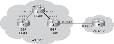
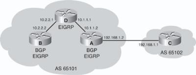
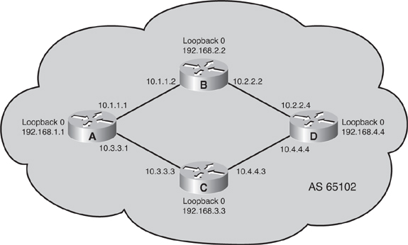
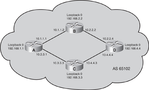


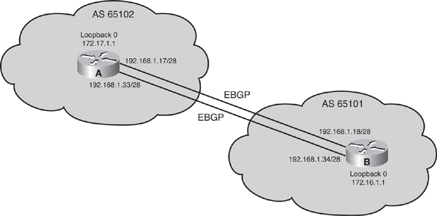
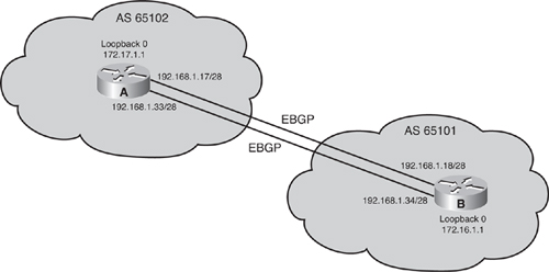
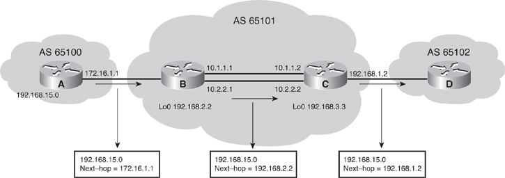
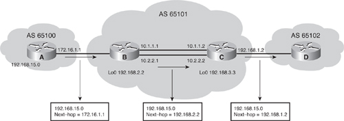


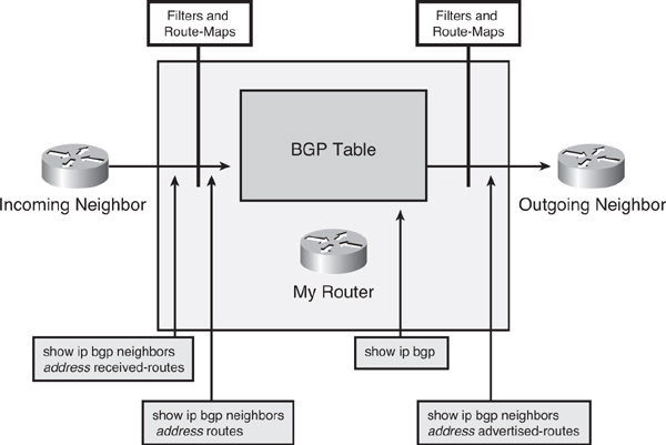
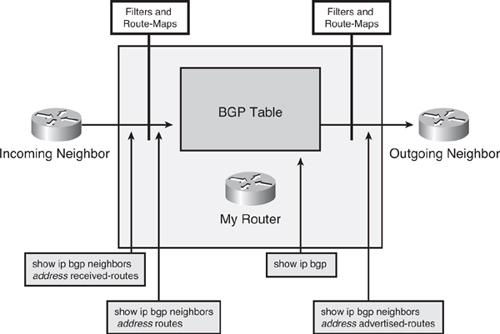


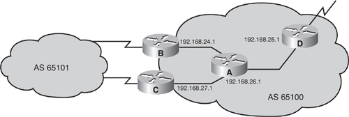
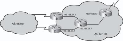
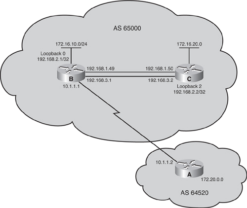
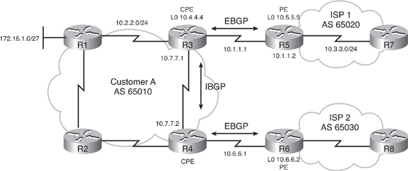
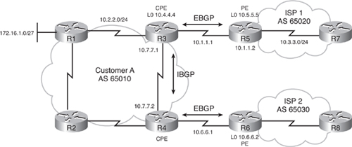
0 comments
Post a Comment