Troubleshooting First-Hop Redundancy Protocols
![]() One of the important elements in building highly available networks is implementing a first-hop redundancy protocol (FHRP). Even if you have multiple routers or multilayer switches on a subnet, the clients and servers will still point to a single default gateway, and they lose connectivity to other subnets if their gateway fails. FHRPs such as the Hot Standby Router Protocol (HSRP), Virtual Router Redundancy Protocol (VRRP), and Gateway Load Balancing Protocol (GLBP) can solve this issue by providing redundant default gateway functionality in a way that is transparent to the end hosts. This section reviews the operation of common FHRPs and shows you how to use Cisco IOS commands to diagnose and resolve problems that might occur while using these protocols.
One of the important elements in building highly available networks is implementing a first-hop redundancy protocol (FHRP). Even if you have multiple routers or multilayer switches on a subnet, the clients and servers will still point to a single default gateway, and they lose connectivity to other subnets if their gateway fails. FHRPs such as the Hot Standby Router Protocol (HSRP), Virtual Router Redundancy Protocol (VRRP), and Gateway Load Balancing Protocol (GLBP) can solve this issue by providing redundant default gateway functionality in a way that is transparent to the end hosts. This section reviews the operation of common FHRPs and shows you how to use Cisco IOS commands to diagnose and resolve problems that might occur while using these protocols.
 Using First-Hop Redundancy
![]() FHRPs such as HSRP, VRRP, and GLBP all serve the same purpose: They provide a redundant default gateway on a subnet and do this in such a way that actions such as failover and load balancing remain entirely transparent to the hosts. These protocols provide a virtual IP address (and the corresponding virtual MAC address) that can be used as the default gateway by the hosts on the subnet. This virtual IP address is not bound to any particular router, but can be controlled by a router within a group of routers participating in the protocol’s scheme. Under normal circumstances, at any given moment, only one router, the active router, has control over the virtual IP address. Consequently, most of the mechanisms of these protocols revolve around the following functions:
FHRPs such as HSRP, VRRP, and GLBP all serve the same purpose: They provide a redundant default gateway on a subnet and do this in such a way that actions such as failover and load balancing remain entirely transparent to the hosts. These protocols provide a virtual IP address (and the corresponding virtual MAC address) that can be used as the default gateway by the hosts on the subnet. This virtual IP address is not bound to any particular router, but can be controlled by a router within a group of routers participating in the protocol’s scheme. Under normal circumstances, at any given moment, only one router, the active router, has control over the virtual IP address. Consequently, most of the mechanisms of these protocols revolve around the following functions:
-
 Electing a single router that controls the virtual IP address
 -
 Tracking availability of the active router
 -
 Determining whether control of the virtual IP address should be handed over to another router
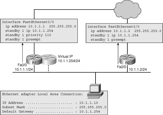
![]() The example shown in Figure 4-19 shows two routers R1 and R2 with IP addresses 10.1.1.1 and 10.1.1.2 on their FastEthernet interfaces, respectively, configured with HSRP. Routers R1 and R2 have been configured for the same HSRP group (group 1) and virtual IP address (10.1.1.254). Both routers have been configured for preemption. This will allow either of them to take over the role of active router when its priority is the highest of the routers in the group. R1 has been configured with a priority of 110, which is higher than the default priority of 100. This will cause R1 to be elected as the active router, while R2 will be elected as the standby router. This means that R1 will be in control of the virtual IP address and will forward packets sent to the virtual router’s IP and MAC address.
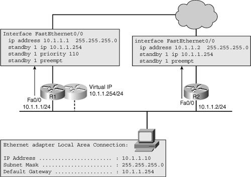
The example shown in Figure 4-19 shows two routers R1 and R2 with IP addresses 10.1.1.1 and 10.1.1.2 on their FastEthernet interfaces, respectively, configured with HSRP. Routers R1 and R2 have been configured for the same HSRP group (group 1) and virtual IP address (10.1.1.254). Both routers have been configured for preemption. This will allow either of them to take over the role of active router when its priority is the highest of the routers in the group. R1 has been configured with a priority of 110, which is higher than the default priority of 100. This will cause R1 to be elected as the active router, while R2 will be elected as the standby router. This means that R1 will be in control of the virtual IP address and will forward packets sent to the virtual router’s IP and MAC address.
![]() When a failure occurs (for example, if the Fast Ethernet interface of R1 goes down), the end hosts that are using the virtual router IP address as their default gateway lose connectivity to destinations outside of their own subnet. For a short period of time, there is no active router and, as a consequence, traffic destined for the virtual router’s IP or MAC address is dropped. After detecting the loss of hello packets from R1, router R2 assumes the active role and ownership of the virtual IP and MAC addresses. At this time, the default gateway on this subnet is functioning again, and hosts within this subnet can resume communication with IP devices outside their subnet. The following types of questions are often raised about the convergence of this type of protocol and the effect on active applications:
When a failure occurs (for example, if the Fast Ethernet interface of R1 goes down), the end hosts that are using the virtual router IP address as their default gateway lose connectivity to destinations outside of their own subnet. For a short period of time, there is no active router and, as a consequence, traffic destined for the virtual router’s IP or MAC address is dropped. After detecting the loss of hello packets from R1, router R2 assumes the active role and ownership of the virtual IP and MAC addresses. At this time, the default gateway on this subnet is functioning again, and hosts within this subnet can resume communication with IP devices outside their subnet. The following types of questions are often raised about the convergence of this type of protocol and the effect on active applications:
-
 What effect does this process have on the network connectivity of the hosts on the subnets?
 -
 How long does it take R2 to discover that R1 is not active any longer?
 -
 How long before R2 takes over the packet-forwarding role?
 -
 What will happen when R1 comes back? Will R1 take over the active router role?
 -
 If R1 comes up, how long will it take for it to take over the active role? Will any packets be dropped during this transition?
![]() Depending on whether the active router has failed, or if the administrator has made configuration changes, the time it takes for the backup (standby) router to take over varies. In case of a physical failure, the only way for the standby router to detect failure of the active router is through the loss of hello packets. By default, both the active and the standby router send hello packets every 3 seconds. If hellos are not received for 10 seconds (the default hold time), the standby router assumes that the active router has disappeared and takes on the active role. This means that for a period of 10 seconds (based on the default timer values), the hosts will lose connectivity because of lack of an active router to forward packets. If the failure is caused by administrative actions such as a shutdown of an interface, reload of the router, or modification of the priority value, the active HSRP router sends a “resign” message, causing the standby router to assume the active role immediately. This means that the 10-second hold time does not come into play.
Depending on whether the active router has failed, or if the administrator has made configuration changes, the time it takes for the backup (standby) router to take over varies. In case of a physical failure, the only way for the standby router to detect failure of the active router is through the loss of hello packets. By default, both the active and the standby router send hello packets every 3 seconds. If hellos are not received for 10 seconds (the default hold time), the standby router assumes that the active router has disappeared and takes on the active role. This means that for a period of 10 seconds (based on the default timer values), the hosts will lose connectivity because of lack of an active router to forward packets. If the failure is caused by administrative actions such as a shutdown of an interface, reload of the router, or modification of the priority value, the active HSRP router sends a “resign” message, causing the standby router to assume the active role immediately. This means that the 10-second hold time does not come into play.
![]() The convergence for the return traffic plays a role in the overall convergence. HSRP is only involved in the convergence of outbound packets that the host sends through the default gateway. Convergence for packets returning to the host is governed by the used routing protocol’s convergence, not HSRP. Therefore, the overall convergence is as fast as the protocol that is the slowest to converge, which could be either HSRP or the routing protocol.
The convergence for the return traffic plays a role in the overall convergence. HSRP is only involved in the convergence of outbound packets that the host sends through the default gateway. Convergence for packets returning to the host is governed by the used routing protocol’s convergence, not HSRP. Therefore, the overall convergence is as fast as the protocol that is the slowest to converge, which could be either HSRP or the routing protocol.
![]() Each router participating in the HSRP process has a priority value, and this value is 100 by default. The router with the higher priority is elected as the active HSRP router, and a tie is broken using the IP address of the contenders. When a router with a higher priority than the active HSRP router loads up or is added, the behavior depends on whether the preempt option has been configured on the added device. When a router with a higher priority or with the same priority but a higher IP address than the current active HSRP router loads up or is added, the behavior depends on what role are we looking at and whether the preempt option has been configured on the added device. An important fact to consider is that the standby role can be preempted at any time and its preemption is not influenced by the preempt option. Assuming that the preempt option has not been configured, the new router will not preempt the current active router. The router that is currently active will stay active. However, if the new router has a higher priority than the current standby router, or the same priority but a higher IP address, it will become the new standby router. It will also become a standby router if there is no standby router currently present.
Each router participating in the HSRP process has a priority value, and this value is 100 by default. The router with the higher priority is elected as the active HSRP router, and a tie is broken using the IP address of the contenders. When a router with a higher priority than the active HSRP router loads up or is added, the behavior depends on whether the preempt option has been configured on the added device. When a router with a higher priority or with the same priority but a higher IP address than the current active HSRP router loads up or is added, the behavior depends on what role are we looking at and whether the preempt option has been configured on the added device. An important fact to consider is that the standby role can be preempted at any time and its preemption is not influenced by the preempt option. Assuming that the preempt option has not been configured, the new router will not preempt the current active router. The router that is currently active will stay active. However, if the new router has a higher priority than the current standby router, or the same priority but a higher IP address, it will become the new standby router. It will also become a standby router if there is no standby router currently present.
![]() If the new router has a higher priority or the same priority but a higher IP address than the current active router, and has been configured with the preempt option, however, it takes over the active role immediately. Overthrowing the standby router does not depend on the configuration of the preempt option. If no standby router is present, the new router simply takes on the standby role. If the new router has a higher priority and has been configured with the preempt option, however, it takes over the active role immediately. It sends out a “coup” message, telling the current active router that it will take over the active role due to its higher priority. You might wonder whether this action will cause any packet loss. The HSRP coup mechanism, in itself, does not cause packet loss because there is an active HSRP router on the segment continuously. Nevertheless, the role that the routing protocol plays cannot be ignored. If the new active router which preempted the previous one has not completed its routing convergence, it might not have a complete forwarding table yet, causing it to drop packets for a period. Therefore, it is important that the new router not assume the active role until it has fully built its routing and forwarding table. The HSRP configuration has a delay option that is used precisely for this reason.
If the new router has a higher priority or the same priority but a higher IP address than the current active router, and has been configured with the preempt option, however, it takes over the active role immediately. Overthrowing the standby router does not depend on the configuration of the preempt option. If no standby router is present, the new router simply takes on the standby role. If the new router has a higher priority and has been configured with the preempt option, however, it takes over the active role immediately. It sends out a “coup” message, telling the current active router that it will take over the active role due to its higher priority. You might wonder whether this action will cause any packet loss. The HSRP coup mechanism, in itself, does not cause packet loss because there is an active HSRP router on the segment continuously. Nevertheless, the role that the routing protocol plays cannot be ignored. If the new active router which preempted the previous one has not completed its routing convergence, it might not have a complete forwarding table yet, causing it to drop packets for a period. Therefore, it is important that the new router not assume the active role until it has fully built its routing and forwarding table. The HSRP configuration has a delay option that is used precisely for this reason.
 Verifying FHRP Operation
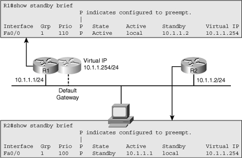
![]() The best way to get a quick overview of the actual HSRP status on the network is to use the show standby brief command. Figure 4-20 shows a sample output from this command for routers R1 and R2 that participate in HSRP group 1. For each interface, this command shows the configured HSRP group, the IP addresses for the active and standby router, the virtual IP address, configured priority, and the preemption option.
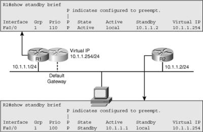
The best way to get a quick overview of the actual HSRP status on the network is to use the show standby brief command. Figure 4-20 shows a sample output from this command for routers R1 and R2 that participate in HSRP group 1. For each interface, this command shows the configured HSRP group, the IP addresses for the active and standby router, the virtual IP address, configured priority, and the preemption option.
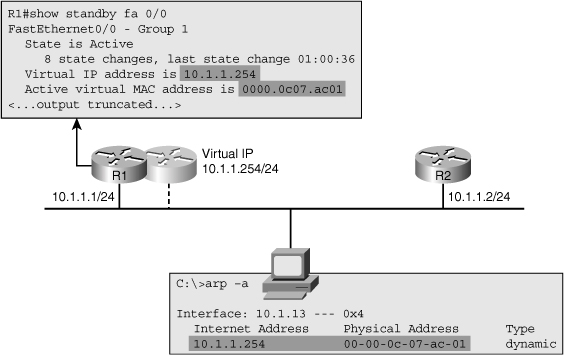
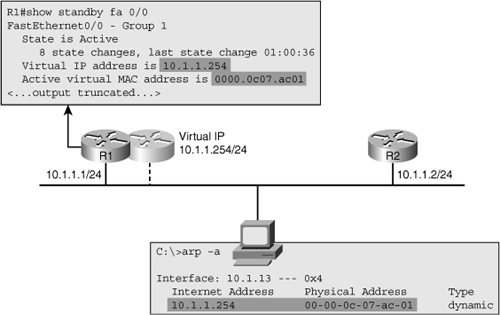
![]() You can obtain more detailed information such as configured timers, the virtual MAC-address for the HSRP group, and information about recent HSRP state changes by using the show standby interface-id command. Figure 4-21 shows the output from this command on R1 for interface Fa0/0. This figure also shows the content of a workstation’s ARP cache, which includes the virtual IP address and MAC address of the HSRP group provided by R1 and R2.
You can obtain more detailed information such as configured timers, the virtual MAC-address for the HSRP group, and information about recent HSRP state changes by using the show standby interface-id command. Figure 4-21 shows the output from this command on R1 for interface Fa0/0. This figure also shows the content of a workstation’s ARP cache, which includes the virtual IP address and MAC address of the HSRP group provided by R1 and R2.
![]() When you are troubleshooting HSRP-related problems, it is useful to know the virtual MAC address used for the standby group because it can be used to verify the correct operation of ARP and the Layer 2 connectivity between the end host and the active HSRP router. In many cases, HSRP-related problems are not really, at the root, caused by HSRP itself, but by problems in the underlying switched network. For example, a typical symptom of a broadcast storm is that you start seeing frequent HSRP state changes on the Layer 3 switches that are connected to the affected VLANs.
When you are troubleshooting HSRP-related problems, it is useful to know the virtual MAC address used for the standby group because it can be used to verify the correct operation of ARP and the Layer 2 connectivity between the end host and the active HSRP router. In many cases, HSRP-related problems are not really, at the root, caused by HSRP itself, but by problems in the underlying switched network. For example, a typical symptom of a broadcast storm is that you start seeing frequent HSRP state changes on the Layer 3 switches that are connected to the affected VLANs.
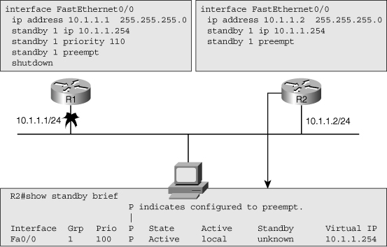
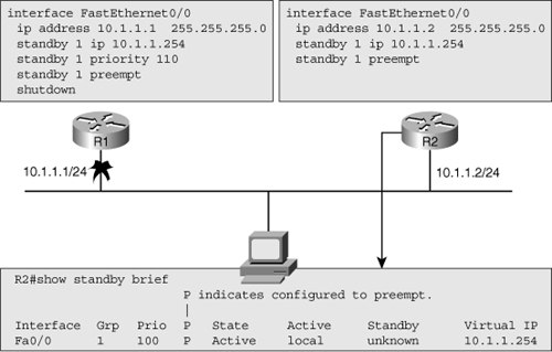
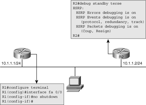
![]() Although the show family of commands is very useful for verification and initial diagnosis, there are times that you need to observe the operation of HSRP in real time to gather clues about the underlying reasons for unexpected behavior or malfunction of HSRP. For example, in Figure 4-22, both routers are configured for HSRP, but the FastEthernet interface on router R1 is currently shut down. Router R2 has become the active router as it is the only member of the HSRP group on that segment.
Although the show family of commands is very useful for verification and initial diagnosis, there are times that you need to observe the operation of HSRP in real time to gather clues about the underlying reasons for unexpected behavior or malfunction of HSRP. For example, in Figure 4-22, both routers are configured for HSRP, but the FastEthernet interface on router R1 is currently shut down. Router R2 has become the active router as it is the only member of the HSRP group on that segment.
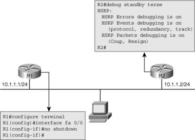
![]() On Figure 4-23, debugging is enabled by use of the debug standby terse command for router R2. This is a good debugging command to start with because it includes most of the relevant messages, but excludes the HSRP hellos, keeping the output of the debug limited and readable.
On Figure 4-23, debugging is enabled by use of the debug standby terse command for router R2. This is a good debugging command to start with because it includes most of the relevant messages, but excludes the HSRP hellos, keeping the output of the debug limited and readable.
![]() As the interface on R1 is administratively enabled, the HSRP process on R2 can be followed using the output of debug shown in Example 4-7.
As the interface on R1 is administratively enabled, the HSRP process on R2 can be followed using the output of debug shown in Example 4-7.
R2#
*Mar  1 00:16:23.555: HSRP: Fa0/0 Grp 1 Coup   in  10.1.1.1 Listen  pri 110 vIP
10.1.1.254
*Mar  1 00:16:23.555: HSRP: Fa0/0 Grp 1 Active: j/Coup rcvd from higher pri
router (110/10.1.1.1)
*Mar  1 00:16:23.555: HSRP: Fa0/0 Grp 1 Active router is 10.1.1.1, was local
*Mar  1 00:16:23.555: HSRP: Fa0/0 Grp 1 Active -> Speak
*Mar  1 00:16:23.555: %HSRP-5-STATECHANGE: FastEthernet0/0 Grp 1 state Active ->
Speak
*Mar  1 00:16:23.555: HSRP: Fa0/0 Grp 1 Redundancy "hsrp-Fa0/0-1" state Active ->
Speak
*Mar  1 00:16:33.555: HSRP: Fa0/0 Grp 1 Speak: d/Standby timer expired (unknown)
*Mar  1 00:16:33.555: HSRP: Fa0/0 Grp 1 Standby router is local
*Mar  1 00:16:33.555: HSRP: Fa0/0 Grp 1 Speak -> Standby

*Mar  1 00:16:33.555: %HSRP-5-STATECHANGE: FastEthernet0/0 Grp 1 state Speak ->
Standby
*Mar  1 00:16:33.559: HSRP: Fa0/0 Grp 1 Redundancy "hsrp-Fa0/0-1" state Speak ->
Standby
R2#
![]() The debugging command output shown in Example 4-7 clearly shows the following actions taking place:
The debugging command output shown in Example 4-7 clearly shows the following actions taking place:
-
 When R1 comes up on the segment, because it has a higher priority than the current active router and it is configured with the preempt option, it sends out a “coup” message to take over the active role.
 -
 R2 loses its active role, causing it to step back to the role of a nonactive, nonstandby HSRP router. Because there is no standby router on the segment, R2 moves to the “speak” state to announce its eligibility for the standby role.
 -
 R2 does not see another (better) candidate for the role of standby router for 10 seconds and, thus, promotes itself to the standby role.
Alternatives to HSRP
![]() Besides HSRP, two other protocols also provide first-hop redundancy: VRRP and GLBP. From a troubleshooting perspective, the methods that you use to troubleshoot these protocols are almost identical. The Cisco IOS commands used to troubleshoot these protocols are also similar in style to the HSRP commands. For VRRP and GLBP troubleshooting commands, you just have to replace the keyword standby with vrrp or glbp.
Besides HSRP, two other protocols also provide first-hop redundancy: VRRP and GLBP. From a troubleshooting perspective, the methods that you use to troubleshoot these protocols are almost identical. The Cisco IOS commands used to troubleshoot these protocols are also similar in style to the HSRP commands. For VRRP and GLBP troubleshooting commands, you just have to replace the keyword standby with vrrp or glbp.
![]() With respect to operation, some differences exist between these protocols. HSRP and GLBP always require an additional IP address to function as the virtual IP address. Consequently, this router will always be the master router for that IP address when it is up because it will automatically claim a priority of 255 that cannot be configured manually. Note that VRRP allows the priority value be manually set to a number between 1 and 254. VRRP is an IETF standard (RFC 3768), which makes it suitable for multivendor environments. HSRP and GLBP do not preempt by default. If you want a higher priority router to take over when it comes up on the segment, you have to configure the preemption option. In VRRP, the higher-priority router preempts by default, but it can be disabled. GLBP can have multiple active routers forwarding traffic for a single virtual IP address at the same time. GLBP achieves this by using multiple virtual MAC addresses for a single virtual IP address. There is still a single router that is in control of the virtual IP address and responds to ARP requests for that IP address. This router effectively balances the load over the different forwarding routers. Default hello timers are also varied: 3 seconds for HSRP, 1 second for VRRP, and 3 seconds for GLBP. Table 4-2 summarizes these differences.
With respect to operation, some differences exist between these protocols. HSRP and GLBP always require an additional IP address to function as the virtual IP address. Consequently, this router will always be the master router for that IP address when it is up because it will automatically claim a priority of 255 that cannot be configured manually. Note that VRRP allows the priority value be manually set to a number between 1 and 254. VRRP is an IETF standard (RFC 3768), which makes it suitable for multivendor environments. HSRP and GLBP do not preempt by default. If you want a higher priority router to take over when it comes up on the segment, you have to configure the preemption option. In VRRP, the higher-priority router preempts by default, but it can be disabled. GLBP can have multiple active routers forwarding traffic for a single virtual IP address at the same time. GLBP achieves this by using multiple virtual MAC addresses for a single virtual IP address. There is still a single router that is in control of the virtual IP address and responds to ARP requests for that IP address. This router effectively balances the load over the different forwarding routers. Default hello timers are also varied: 3 seconds for HSRP, 1 second for VRRP, and 3 seconds for GLBP. Table 4-2 summarizes these differences.
|
|
|
|
|
|---|---|---|---|
|
|
|
|
|
|
|
|
|
|
|
|
|
|
|
|
|
|
|
|
|
|
|
|
|
|
|
|
|
|
![]() Example 4-8 shows the output of the show standby brief, show vrrp brief, and show glbp brief commands. The structure of the major troubleshooting commands for HSRP, VRRP, and GLBP are similar. If you know how to interpret the output of the commands for one of these protocols, it is quite easy to do the same for the others.
Example 4-8 shows the output of the show standby brief, show vrrp brief, and show glbp brief commands. The structure of the major troubleshooting commands for HSRP, VRRP, and GLBP are similar. If you know how to interpret the output of the commands for one of these protocols, it is quite easy to do the same for the others.
R1# show standby brief
                      P indicates configured to preempt.
                      |
Interface   Grp Prio P State     Active           Standby         Virtual IP
Fa0/0        1  110  P Active    local            10.1.1.2        10.1.1.254
...
R1# show vrrp brief
Interface          Grp Pri Time   Own Pre State   Master addr     Group addr
Fa0/0              1   110 3570        Y  Master  10.1.1.1        10.1.1.254
...
R1# show glbp brief
Interface   Grp  Fwd Pri State    Address         Active router   Standby router
Fa0/0       1     -  110 Active   10.1.1.254      local           10.1.1.2
Fa0/0       1     1   -  Active   0007.b400.0101  local            -
Fa0/0       1     2   -  Listen   0007.b400.0102  10.1.1.2         -
![]() Table 4-3 lists the typical troubleshooting commands for HSRP, VRRP, and GLBP. Note that there is no debug terse option for VRRP. This means that each debug option that you are interested in must be entered manually.
Table 4-3 lists the typical troubleshooting commands for HSRP, VRRP, and GLBP. Note that there is no debug terse option for VRRP. This means that each debug option that you are interested in must be entered manually.
|
|
|
|
|---|---|---|
|
|
|
|
|
|
|
|
|
|
|
|
Summary
![]() Some commonly used diagnostic commands that help you obtain information about the Layer 2 switching process, VLANs, and trunks are as follows:
Some commonly used diagnostic commands that help you obtain information about the Layer 2 switching process, VLANs, and trunks are as follows:
-
 show mac address-table
 -
 show vlan
 -
 show interfaces trunk
 -
 show interfaces switchport
 -
 show platform forward interface
 -
 traceroute mac
![]() Building the spanning tree requires the following four main steps:
Building the spanning tree requires the following four main steps:
|
|
|
|
|
|
|
|
|
|
|
|
![]() Important commands for gathering information about the status of STP and the corresponding topology include the following:
Important commands for gathering information about the status of STP and the corresponding topology include the following:
-
 show spanning-tree [vlan vlan-id]
 -
 show spanning-tree interface interface-id detail
![]() The consequences and corresponding symptoms of broadcast (or unknown MAC) storms include the following:
The consequences and corresponding symptoms of broadcast (or unknown MAC) storms include the following:
-
 The load on all links in the switched LAN will quickly start increasing as more and more frames enter the loop.
 -
 If the spanning-tree failure has caused more than one bridging loop to form, traffic will increase exponentially.
 -
 When control plane traffic start entering the loop, the devices that are running these protocols will quickly start getting overloaded, and their CPU will approach 100 percent utilization.
 -
 Switches will experience frequent MAC address table changes.
 -
 Because of the combination of very high load on all links and the CPU running at maximum load on Layer 3 switches or routers, these devices typically become unreachable, making it nearly impossible to diagnose the problem while it is in progress.
![]() Three common EtherChannel problems are as follows:
Three common EtherChannel problems are as follows:
-
 Inconsistencies between the physical ports that are members of the channel (a %EC-5-CANNOT_BUNDLE2 log message is generated)
 -
 Inconsistencies between the ports on the opposite sides of the EtherChannel link (The switch will generate a %SPANTREE-2-CHNL_MISCFG message)
 -
 Uneven distribution of traffic between EtherChannel bundle members
![]() The similarities between multilayer switches and routers are as follows:
The similarities between multilayer switches and routers are as follows:
-
 Both routers and multilayer switches use routing protocols or static routes to maintain information about the reachability and direction to network destinations (prefixes) and record this information in a routing table.
 -
 Both routers and multilayer switches perform the same functional packet switching actions:
|
|
|
|
|
|
|
|
|
![]() The differences between multilayer switches and routers are as follows:
The differences between multilayer switches and routers are as follows:
-
 Routers connect heterogeneous networks and support a wide variety of media and inter-faces. Multilayer switches typically connect homogenous networks. Nowadays, LAN switches are mostly Ethernet only.
 -
 Multilayer switches use specialized hardware to achieve wire-speed Ethernet-to-Ethernet packet switching. Low- to mid-range routers use multipurpose hardware to perform the packet-switching process. On average, the packet-switching throughput of routers is lower than the packet-switching throughput of multilayer switches.
 -
 Routers usually support a wider range of features, mainly because switches need specialized hardware to be able to support certain data plane features or protocols. On routers, you can often add features through a software update.
![]() There are two main commands to check the CEF data structures:
There are two main commands to check the CEF data structures:
-
 show ip cef
 -
 show adjacency
![]() To extract information about the forwarding behavior of switches from the TCAMs on some of the common Cisco Catalyst series switches, you can use the following commands:
To extract information about the forwarding behavior of switches from the TCAMs on some of the common Cisco Catalyst series switches, you can use the following commands:
-
 show platform
 -
 show mls cef
![]() A multilayer switch provides three different core functions in a single device:
A multilayer switch provides three different core functions in a single device:
-
 Layer 2 switching within each VLAN
 -
 Routing and multilayer switching between the local VLANs
 -
 Routing and multilayer switching between the local VLANs and one or more routed interfaces
![]() The main differences between SVIs and router interfaces are as follows:
The main differences between SVIs and router interfaces are as follows:
-
 A routed port is not a Layer 2 port. This means that on a routed port typical Layer 2 protocols that are enabled by default, such as STP and DTP, are not active.
 -
 A direct relationship exists between the status of a routed port and the availability of the corresponding directly connected subnet. When/if the port goes down, the corresponding connected route is immediately removed from the routing table.
![]() Among first-hop redundancy protocols, VRRP is the only standards-based protocol, the only one that has the preempt option enabled by default, and the only one that allows the virtual IP address to also be a real address assigned to one of the participating routers. VRRP’s default hello timer is 1 second, as opposed to HSRP’s and GLBP’s 3-second default hello timer. Among HSRP, VRRP, and GLBP, only GLBP makes use of multiple routers in the group to do simultaneous forwarding (load balancing). With respect to debug, VRRP does not have the terse option, but HSRP and GLBP do.
Among first-hop redundancy protocols, VRRP is the only standards-based protocol, the only one that has the preempt option enabled by default, and the only one that allows the virtual IP address to also be a real address assigned to one of the participating routers. VRRP’s default hello timer is 1 second, as opposed to HSRP’s and GLBP’s 3-second default hello timer. Among HSRP, VRRP, and GLBP, only GLBP makes use of multiple routers in the group to do simultaneous forwarding (load balancing). With respect to debug, VRRP does not have the terse option, but HSRP and GLBP do.

0 comments
Post a Comment