Rapid Spanning Tree Protocol
![]() Rapid Spanning Tree Protocol (IEEE 802.1w, also referred to as RSTP) significantly speeds the recalculation of the spanning tree when the network topology changes. RSTP defines the additional port roles of Alternate and Backup and defines port states as discarding, learning, or forwarding. This section describes the differences between STP (802.1D) and RSTP (802.1w).
Rapid Spanning Tree Protocol (IEEE 802.1w, also referred to as RSTP) significantly speeds the recalculation of the spanning tree when the network topology changes. RSTP defines the additional port roles of Alternate and Backup and defines port states as discarding, learning, or forwarding. This section describes the differences between STP (802.1D) and RSTP (802.1w).
![]() The 802.1D STP standard was designed with the understanding that recovering connectivity after an outage within a minute or so gives adequate performance. With the advent of Layer 3 switching in LAN environments, bridging now competes with routed solutions, in which protocols such as Open Shortest Path First (OSPF) and Enhanced Interior Gateway Routing Protocol (EIGRP) can provide an alternative path in approximately 1 second.
The 802.1D STP standard was designed with the understanding that recovering connectivity after an outage within a minute or so gives adequate performance. With the advent of Layer 3 switching in LAN environments, bridging now competes with routed solutions, in which protocols such as Open Shortest Path First (OSPF) and Enhanced Interior Gateway Routing Protocol (EIGRP) can provide an alternative path in approximately 1 second.
![]() Cisco enhanced the original 802.1D specification with features such as UplinkFast, BackboneFast, and PortFast to speed up the convergence time of a bridged network. The drawback is that these mechanisms are proprietary and need additional configuration.
Cisco enhanced the original 802.1D specification with features such as UplinkFast, BackboneFast, and PortFast to speed up the convergence time of a bridged network. The drawback is that these mechanisms are proprietary and need additional configuration.
![]() The IEEE 802.1w standard (RSTP) is an evolution, rather than a revolution, of the 802.1D standard. The 802.1D terminology remains primarily the same, and most parameters are left unchanged, so users who are familiar with 802.1D can rapidly feel at home when configuring the new protocol. In most cases, RSTP performs better than the Cisco proprietary extensions, with negligible additional configuration. In addition, 802.1w can revert to 802.1D to interoperate with legacy bridges on a per-port basis. Reverting to 802.1D negates the benefits of 802.1w for that particular segment.
The IEEE 802.1w standard (RSTP) is an evolution, rather than a revolution, of the 802.1D standard. The 802.1D terminology remains primarily the same, and most parameters are left unchanged, so users who are familiar with 802.1D can rapidly feel at home when configuring the new protocol. In most cases, RSTP performs better than the Cisco proprietary extensions, with negligible additional configuration. In addition, 802.1w can revert to 802.1D to interoperate with legacy bridges on a per-port basis. Reverting to 802.1D negates the benefits of 802.1w for that particular segment.
![]() RSTP selects one switch as the root of an active spanning-tree–connected topology and assigns port roles to individual ports on the switch, depending on whether the ports are part of the active topology.
RSTP selects one switch as the root of an active spanning-tree–connected topology and assigns port roles to individual ports on the switch, depending on whether the ports are part of the active topology.
![]() RSTP provides rapid connectivity following the failure of a switch, switch port, or LAN. A new root port and the designated port of the connecting bridge transition to forwarding through an explicit handshake protocol between them. RSTP enables switch-port configuration so that the ports transition to forwarding directly when the switch reinitializes.
RSTP provides rapid connectivity following the failure of a switch, switch port, or LAN. A new root port and the designated port of the connecting bridge transition to forwarding through an explicit handshake protocol between them. RSTP enables switch-port configuration so that the ports transition to forwarding directly when the switch reinitializes.
![]() On Cisco Catalyst switches, a rapid version of PVST+, called PVRST+, is the per-VLAN version of the RSTP implementation. All the current generation of Catalyst switches supports PVRST+.
On Cisco Catalyst switches, a rapid version of PVST+, called PVRST+, is the per-VLAN version of the RSTP implementation. All the current generation of Catalyst switches supports PVRST+.
 RSTP Port States
![]() RSTP has only three port states, corresponding to the three possible operational statuses: discarding, learning, and forwarding. The RSTP 802.1w discarding state represents a merger of the 802.1D STP port states of disabled, blocking, and listening.
RSTP has only three port states, corresponding to the three possible operational statuses: discarding, learning, and forwarding. The RSTP 802.1w discarding state represents a merger of the 802.1D STP port states of disabled, blocking, and listening.
![]() Table 3-3 describes the characteristics of RSTP port states.
Table 3-3 describes the characteristics of RSTP port states.
|
|
|
|---|---|
|
|
|
|
|
|
|
|
|
![]() IEEE 802.1D STP mixes the state of a port, whether blocking or forwarding traffic, with the role it plays in the active topology (root port, designated port, and so on). For example, from an operational point of view, there is no difference between a port in the blocking state and a port in the listening state. Both discard frames and do not learn MAC addresses. The real difference lies in the role the spanning tree assigns to the port. It can safely be assumed that a listening port is either designated or root and is on its way to the forwarding state. Unfortunately, when in the forwarding state, there is no way to infer from the port state whether the port is root or designated. RSTP considers there to be no difference between a port in blocking state and a port in listening state; both discard frames, and neither learns MAC addresses. RSTP decouples the role of a port from the state of a port. In all port states, a port will accept and process BPDU frames. Table 3-4 provides a comparison of 802.1D port states with RSTP port states.
IEEE 802.1D STP mixes the state of a port, whether blocking or forwarding traffic, with the role it plays in the active topology (root port, designated port, and so on). For example, from an operational point of view, there is no difference between a port in the blocking state and a port in the listening state. Both discard frames and do not learn MAC addresses. The real difference lies in the role the spanning tree assigns to the port. It can safely be assumed that a listening port is either designated or root and is on its way to the forwarding state. Unfortunately, when in the forwarding state, there is no way to infer from the port state whether the port is root or designated. RSTP considers there to be no difference between a port in blocking state and a port in listening state; both discard frames, and neither learns MAC addresses. RSTP decouples the role of a port from the state of a port. In all port states, a port will accept and process BPDU frames. Table 3-4 provides a comparison of 802.1D port states with RSTP port states.
|
|
|
| |
|---|---|---|---|
|
|
|
|
|
|
|
|
|
|
|
|
|
|
|
|
|
|
|
|
|
|
|
|
|
 RSTP Port Roles
![]() The port role defines the ultimate purpose of a switch port and the way it handles data frames. One strength of RSTP is that port roles and port states can transition independently of each other. RSTP defines the port roles as follows:
The port role defines the ultimate purpose of a switch port and the way it handles data frames. One strength of RSTP is that port roles and port states can transition independently of each other. RSTP defines the port roles as follows:
-
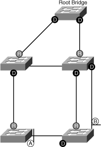
 Root: The root port is the switch port on every nonroot bridge that is the chosen path to the root bridge. Only one root port can be on every switch. The root port assumes the forwarding state in a stable active topology. In Figure 3-4, the root port is marked as R.
 -
 Designated: Each segment has at least one switch port as the designated port for that segment. In a stable, active topology, the switch with the designated port receives frames on the segment that are destined for the root bridge. There can be only one designated port per segment. The designated port assumes the forwarding state. All switches that are connected to a given segment listen to all BPDUs and determine the switch that will be the designated switch for a particular segment. In Figure 3-4, the designated port is marked as D.
 -
 Alternate: The alternate port is a switch port that offers an alternative path toward the root bridge. The alternate port assumes a discarding state in a stable, active topology. An alternate port is present on nondesignated switches and makes a transition to a designated port if the current designated path fails. In Figure 3-4, the alternate port is marked as A.
 -
 Backup: The backup port is an additional switch port on the designated switch with a redundant link to the segment for which the switch is designated. A backup port has a higher port ID than the designated port on the designated switch. The backup port assumes the discarding state in a stable, active topology. In Figure 3-4, the backup port is marked as B.
 -
 Disabled: A port that has no role within the operation of spanning tree.
![]() Root and designated port roles include the port in the active topology. Alternate and backup port roles exclude the port from the active topology. Table 3-5 compares the 802.1D port role and the RSTP port roles.
Root and designated port roles include the port in the active topology. Alternate and backup port roles exclude the port from the active topology. Table 3-5 compares the 802.1D port role and the RSTP port roles.
|
|
|
|
|
|---|---|---|---|
|
|
|
|
|
|
|
|
|
|
|
|
|
|
|
|
|
|
|
|
|
|
|
|
|
![]() Establishing the additional port roles allows RSTP to define a standby switch port before a failure or topology change. The alternate port moves to the forwarding state if a failure occurs on the designated port for the segment.
Establishing the additional port roles allows RSTP to define a standby switch port before a failure or topology change. The alternate port moves to the forwarding state if a failure occurs on the designated port for the segment.
 Rapid Transition to Forwarding
![]() Rapid transition to forwarding is the most important feature introduced with IEEE 802.1w. Before the introduction of 802.1w, the spanning tree algorithm waited passively for the network to converge before transitioning a port to the forwarding state. The RSTP algorithm confirms that a port transition to forwarding is safe without relying on a timer configuration. To achieve fast convergence on a port, the protocol relies on two new variables:
Rapid transition to forwarding is the most important feature introduced with IEEE 802.1w. Before the introduction of 802.1w, the spanning tree algorithm waited passively for the network to converge before transitioning a port to the forwarding state. The RSTP algorithm confirms that a port transition to forwarding is safe without relying on a timer configuration. To achieve fast convergence on a port, the protocol relies on two new variables:
-
 Link type
 -
 Edge port
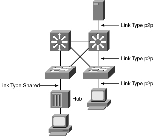
![]() Link type provides a categorization for each port participating in RSTP. The link type is automatically derived from the duplex mode of a port. A port that operates in full-duplex is assumed to be point-to-point, whereas a half-duplex port is considered a shared port by default. This automatic link type setting can be overridden by explicit configuration. In switched networks today, most links operate in full-duplex mode and are treated as point-to-point links by RSTP. This makes them candidates for rapid transition to the forwarding state. Figure 3-5 illustrates the RSTP link type depending on the port operating mode.
Link type provides a categorization for each port participating in RSTP. The link type is automatically derived from the duplex mode of a port. A port that operates in full-duplex is assumed to be point-to-point, whereas a half-duplex port is considered a shared port by default. This automatic link type setting can be overridden by explicit configuration. In switched networks today, most links operate in full-duplex mode and are treated as point-to-point links by RSTP. This makes them candidates for rapid transition to the forwarding state. Figure 3-5 illustrates the RSTP link type depending on the port operating mode.
![]() Table 3-6 defines RSTP link types.
Table 3-6 defines RSTP link types.
|
|
|
|---|---|
|
|
|
|
|
|
![]() Ports that are directly connected to end stations typically cannot create bridging loops in the network; therefore, they are allowed to transition directly to forwarding, skipping the listening and learning stages. Such ports are designated as edge ports through manual configuration. An edge port does not generate a topology change when its link transitions. If an edge port receives a BPDU, it immediately loses its edge port status and becomes a normal spanning-tree port.
Ports that are directly connected to end stations typically cannot create bridging loops in the network; therefore, they are allowed to transition directly to forwarding, skipping the listening and learning stages. Such ports are designated as edge ports through manual configuration. An edge port does not generate a topology change when its link transitions. If an edge port receives a BPDU, it immediately loses its edge port status and becomes a normal spanning-tree port.
![]() Edge ports, the equivalent of PortFast-enabled ports, and point-to-point links are candidates for rapid transition to a forwarding state. Before the link type parameter can be considered for the purpose of expedient port transition, RSTP must determine the port role.
Edge ports, the equivalent of PortFast-enabled ports, and point-to-point links are candidates for rapid transition to a forwarding state. Before the link type parameter can be considered for the purpose of expedient port transition, RSTP must determine the port role.
-
 Root ports: Do not use the link type parameter. Root ports can make a rapid transition to the forwarding state as soon as the port receives the BPDU of the root and it puts the nondesignated ports in blocking state. This operation is called sync.
 -
 Alternative and backup ports: Do not use the link type parameter in most cases because these ports need to arrive at these states based on the operation of the RSTP. The only times you would configure link type parameter explicitly is when you understand the final state of these ports due to your full understanding of the topology.
 -
 Designated ports: Make the most use of the link type parameter. Rapid transition to the forwarding state for the designated port occurs only if the link type parameter indicates a point-to-point link.
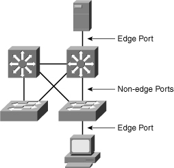
![]() An RSTP edge port is a switch port that is never intended to be connected to another switch device, as shown in Figure 3-6. It immediately transitions to the forwarding state when enabled.
An RSTP edge port is a switch port that is never intended to be connected to another switch device, as shown in Figure 3-6. It immediately transitions to the forwarding state when enabled.
![]() The edge port concept is well known to Cisco spanning-tree users because it corresponds to the PortFast feature (explained in a later section titled “Portfast”) . All ports that directly connect to end stations anticipate that no switch device will be connected to them, so they immediately transition to the STP forwarding state, thereby skipping the time-consuming listening and learning stages. Neither edge ports nor PortFast-enabled ports generate topology changes when the port transitions to a disabled or enabled status.
The edge port concept is well known to Cisco spanning-tree users because it corresponds to the PortFast feature (explained in a later section titled “Portfast”) . All ports that directly connect to end stations anticipate that no switch device will be connected to them, so they immediately transition to the STP forwarding state, thereby skipping the time-consuming listening and learning stages. Neither edge ports nor PortFast-enabled ports generate topology changes when the port transitions to a disabled or enabled status.
![]() Unlike PortFast, an edge port that receives a BPDU immediately loses its edge port status and becomes a normal spanning-tree port. When an edge port receives a BPDU, it generates a topology change notification (TCN).
Unlike PortFast, an edge port that receives a BPDU immediately loses its edge port status and becomes a normal spanning-tree port. When an edge port receives a BPDU, it generates a topology change notification (TCN).
![]() The Cisco RSTP implementation maintains the PortFast keyword for edge port configuration, thus making an overall network transition to RSTP more seamless. Configuring an edge port where the port will be attached to another switch can have negative implications for RSTP when it is in the “sync” state.
The Cisco RSTP implementation maintains the PortFast keyword for edge port configuration, thus making an overall network transition to RSTP more seamless. Configuring an edge port where the port will be attached to another switch can have negative implications for RSTP when it is in the “sync” state.
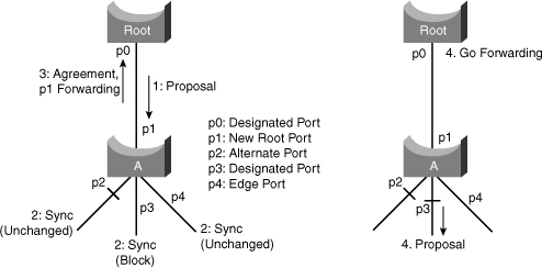
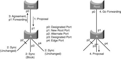
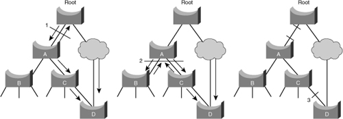
![]() When a port is selected by the spanning tree algorithm to become a designated port, 802.1D still waits two times the forward delay seconds (2 × 15 by default) before it transitions it to the forwarding state. In RSTP, this condition corresponds to a port with a designated role but a blocking state. Figure 3-7 is a step-by-step illustration of the fast transition achieved in RSTP. Suppose a new link is created between the root and Switch A. Both ports on this link are put in a designated blocking state until they receive a BPDU from their counterpart.
When a port is selected by the spanning tree algorithm to become a designated port, 802.1D still waits two times the forward delay seconds (2 × 15 by default) before it transitions it to the forwarding state. In RSTP, this condition corresponds to a port with a designated role but a blocking state. Figure 3-7 is a step-by-step illustration of the fast transition achieved in RSTP. Suppose a new link is created between the root and Switch A. Both ports on this link are put in a designated blocking state until they receive a BPDU from their counterpart.
![]() When a designated port is in a discarding or learning state (and only in this case), it sets the proposal bit on the BPDUs it sends out. This is what occurs for port p0 of the root bridge, as shown in Step 1 of Figure 3-7. Because Switch A receives superior information, it immediately knows that p1 is the new root port. Switch A then starts a sync process that puts nonedge designated ports in blocking state as it needs to verify that all its ports are in-sync with the new superior BPDU received.
When a designated port is in a discarding or learning state (and only in this case), it sets the proposal bit on the BPDUs it sends out. This is what occurs for port p0 of the root bridge, as shown in Step 1 of Figure 3-7. Because Switch A receives superior information, it immediately knows that p1 is the new root port. Switch A then starts a sync process that puts nonedge designated ports in blocking state as it needs to verify that all its ports are in-sync with the new superior BPDU received.
![]() To illustrate the effect of the sync mechanism on different kind of ports, suppose that there exists an alternative Port p2 and a designated forwarding Port p3 on Switch A. To be in sync, Switch A just needs to block Port p3 and assign it the discarding state. Now that all of its ports are in sync, Switch A can unblock its newly selected root, Port p1, and send an agreement message to reply to the root. This message is a copy of the proposal BPDU with the agreement bit set instead of the proposal bit. This ensures that Port p0 knows exactly to which proposal the agreement it receives corresponds.
To illustrate the effect of the sync mechanism on different kind of ports, suppose that there exists an alternative Port p2 and a designated forwarding Port p3 on Switch A. To be in sync, Switch A just needs to block Port p3 and assign it the discarding state. Now that all of its ports are in sync, Switch A can unblock its newly selected root, Port p1, and send an agreement message to reply to the root. This message is a copy of the proposal BPDU with the agreement bit set instead of the proposal bit. This ensures that Port p0 knows exactly to which proposal the agreement it receives corresponds.
![]() When p0 receives that agreement, it can immediately transition to the forwarding state. Root then starts to propose to its neighbor and attempts to quickly transition to the forwarding state. The proposal agreement mechanism is fast because it does not rely on any timers. This wave of handshakes propagates quickly toward the edge of the network and quickly restores connectivity after a change in the topology. If a designated discarding port does not receive an agreement after it sends a proposal, it slowly transitions to the forwarding state by falling back to the traditional 802.1D listening-learning sequence. This can occur if the remote bridge does not understand RSTP BPDUs or if the port of the remote bridge is blocking.
When p0 receives that agreement, it can immediately transition to the forwarding state. Root then starts to propose to its neighbor and attempts to quickly transition to the forwarding state. The proposal agreement mechanism is fast because it does not rely on any timers. This wave of handshakes propagates quickly toward the edge of the network and quickly restores connectivity after a change in the topology. If a designated discarding port does not receive an agreement after it sends a proposal, it slowly transitions to the forwarding state by falling back to the traditional 802.1D listening-learning sequence. This can occur if the remote bridge does not understand RSTP BPDUs or if the port of the remote bridge is blocking.
![]() When a bridge loses its root port, it can put its best alternate port directly into forwarding mode. The selection of an alternate port as the new root port generates a topology change. The 802.1w topology change mechanism, discussed in the next section, clears the appropriate entries in the MAC address tables of the upstream bridges.
When a bridge loses its root port, it can put its best alternate port directly into forwarding mode. The selection of an alternate port as the new root port generates a topology change. The 802.1w topology change mechanism, discussed in the next section, clears the appropriate entries in the MAC address tables of the upstream bridges.
 RSTP Topology Change Mechanism
![]() When an 802.1D bridge detects a topology change, it first notifies the root bridge by using a reliable mechanism. After the root bridge is aware of a change in the topology of the network, it sets the TC flag on the BPDUs that it sends out, which then gets relayed to all the bridges in the network through the normal mechanism. When a bridge receives a BPDU with the TC flag bit set, it reduces its bridging-table aging time to forward-delay seconds, ensuring a relatively quick flushing of stale information.
When an 802.1D bridge detects a topology change, it first notifies the root bridge by using a reliable mechanism. After the root bridge is aware of a change in the topology of the network, it sets the TC flag on the BPDUs that it sends out, which then gets relayed to all the bridges in the network through the normal mechanism. When a bridge receives a BPDU with the TC flag bit set, it reduces its bridging-table aging time to forward-delay seconds, ensuring a relatively quick flushing of stale information.
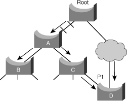
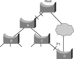
![]() In the scenario in Figure 3-8, a link between the root bridge and Bridge A is added. Suppose there already is an indirect connection between Bridge A and the root bridge (via C to D in Figure 3-8). The spanning tree algorithm blocks a port and disables the bridging loop. First, as they come up, both ports on the link between the root and Bridge A are put in the listening state. Bridge A can now hear the root directly. It immediately propagates its BPDUs on the designated ports toward the leaves of the tree. As soon as Bridges B and C receive this new superior information from Bridge A, they immediately relay the information toward the leaves. In a few seconds, Bridge D receives a BPDU from the root and instantly blocks Port p1. Spanning tree is efficient in how it calculates the new topology of the network. The only problem now is that twice the forward delay must elapse before the link between the root and Bridge A eventually ends up in the forwarding state, as shown in Figure 3-9. This means 30 seconds of disruption of traffic (the entire A, B, and C part of the network is isolated) because the 8021.D algorithm lacks a feedback mechanism to clearly advertise that the network converges in a matter of seconds.
In the scenario in Figure 3-8, a link between the root bridge and Bridge A is added. Suppose there already is an indirect connection between Bridge A and the root bridge (via C to D in Figure 3-8). The spanning tree algorithm blocks a port and disables the bridging loop. First, as they come up, both ports on the link between the root and Bridge A are put in the listening state. Bridge A can now hear the root directly. It immediately propagates its BPDUs on the designated ports toward the leaves of the tree. As soon as Bridges B and C receive this new superior information from Bridge A, they immediately relay the information toward the leaves. In a few seconds, Bridge D receives a BPDU from the root and instantly blocks Port p1. Spanning tree is efficient in how it calculates the new topology of the network. The only problem now is that twice the forward delay must elapse before the link between the root and Bridge A eventually ends up in the forwarding state, as shown in Figure 3-9. This means 30 seconds of disruption of traffic (the entire A, B, and C part of the network is isolated) because the 8021.D algorithm lacks a feedback mechanism to clearly advertise that the network converges in a matter of seconds.
![]() In RSTP, only nonedge ports that are moving to the forwarding state cause a topology change. Unlike with 802.1D, loss of connectivity does not generate a topology change. In other words, a port that is moving to blocking does not cause the respective bridge to generate a TC BPDU.
In RSTP, only nonedge ports that are moving to the forwarding state cause a topology change. Unlike with 802.1D, loss of connectivity does not generate a topology change. In other words, a port that is moving to blocking does not cause the respective bridge to generate a TC BPDU.
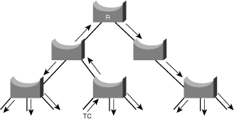
![]() When an RSTP bridge detects a topology change, as depicted in Figure 3-10, it performs these actions:
When an RSTP bridge detects a topology change, as depicted in Figure 3-10, it performs these actions:
-
 The RSTP bridge starts the TC While timer with a value equal to twice the hello time for all its nonedge designated ports and its root port, if necessary. The TC While timer is the interval during which the RSTP bridge actively informs the rest of the bridges in the network of a topology change.
 -
 The RSTP bridge flushes the MAC addresses associated with all nonedge ports.
 -
 As long as the TC While timer is running on a port, the BPDUs sent out of that port have the TC bit set. While the timer is active, the bridge sends BPDUs even on the root port.
![]() When a bridge receives a BPDU with the TC bit set from a neighbor, the bridge performs these actions:
When a bridge receives a BPDU with the TC bit set from a neighbor, the bridge performs these actions:
-
 The bridge clears the MAC addresses learned on all its ports, except the one that received the topology change.
 -
 The bridge starts the TC While timer and sends BPDUs with TC set on all its designated ports and root port; RSTP does not use the specific TCN BPDU anymore unless a legacy bridge needs to be notified.
![]() The topology change propagation is now a one-step process. In fact, the initiator of the topology change is flooding this information throughout the network, as opposed to with 802.1D, where only the root sends BPDUs with the TC bit set. This mechanism is much faster than the 802.1D equivalent. In RSTP implementation, there is no need to wait for the root bridge to be notified and then maintain the topology change state for the whole network for the value of the max age timer plus the value of the forward delay timer.
The topology change propagation is now a one-step process. In fact, the initiator of the topology change is flooding this information throughout the network, as opposed to with 802.1D, where only the root sends BPDUs with the TC bit set. This mechanism is much faster than the 802.1D equivalent. In RSTP implementation, there is no need to wait for the root bridge to be notified and then maintain the topology change state for the whole network for the value of the max age timer plus the value of the forward delay timer.
![]() Now, you can see how RSTP deals with a similar situation, as shown in Figure 3-10. Both ports on the link between A and the root are put in designated blocking as soon as they come up. Thus far, everything behaves as in a pure 802.1D environment. However, at this stage, a negotiation takes place between Switch A and the root. As soon as A receives the BPDU of the root, it blocks the nonedge designated ports. This operation is called sync. When this is done, Bridge A explicitly authorizes the root bridge to put its port in the forwarding state. Figure 3-11 illustrates the result of this process on the network. The link between Switch A and the root bridge is blocked, and both bridges exchange BPDUs.
Now, you can see how RSTP deals with a similar situation, as shown in Figure 3-10. Both ports on the link between A and the root are put in designated blocking as soon as they come up. Thus far, everything behaves as in a pure 802.1D environment. However, at this stage, a negotiation takes place between Switch A and the root. As soon as A receives the BPDU of the root, it blocks the nonedge designated ports. This operation is called sync. When this is done, Bridge A explicitly authorizes the root bridge to put its port in the forwarding state. Figure 3-11 illustrates the result of this process on the network. The link between Switch A and the root bridge is blocked, and both bridges exchange BPDUs.
![]() When Switch A blocks its nonedge designated ports, the link between Switch A and the root is put in the forwarding state. There still cannot be a loop. Instead of blocking above Switch A, the network now blocks below Switch A. However, the potential bridging loop is cut at a different location. This cut travels down the tree along with the new BPDUs originated by the root through Switch A. At this stage, the newly blocked ports on Switch A also negotiate a quick transition to the forwarding state with their neighbor ports on Switch B and Switch C that both initiate a sync operation. Other than the root port toward A, Switch B only has edge-designated ports. Therefore, it has no port to block to authorize Switch A to go to the forwarding state. Similarly, Switch C only has to block its designated port to D.
When Switch A blocks its nonedge designated ports, the link between Switch A and the root is put in the forwarding state. There still cannot be a loop. Instead of blocking above Switch A, the network now blocks below Switch A. However, the potential bridging loop is cut at a different location. This cut travels down the tree along with the new BPDUs originated by the root through Switch A. At this stage, the newly blocked ports on Switch A also negotiate a quick transition to the forwarding state with their neighbor ports on Switch B and Switch C that both initiate a sync operation. Other than the root port toward A, Switch B only has edge-designated ports. Therefore, it has no port to block to authorize Switch A to go to the forwarding state. Similarly, Switch C only has to block its designated port to D.
![]() Remember that the final topology is exactly the same as the 802.1D example, which means that port p1 on D ends up blocking. This means that the final network topology is reached, just in the time necessary for the new BPDUs to travel down the tree. No timer is involved in this quick convergence. The only new mechanism introduced by RSTP is the acknowledgment that a switch can send on its new root port to authorize immediate transition to the forwarding state and bypass the twice-the-forward-delay long listening and learning stages.
Remember that the final topology is exactly the same as the 802.1D example, which means that port p1 on D ends up blocking. This means that the final network topology is reached, just in the time necessary for the new BPDUs to travel down the tree. No timer is involved in this quick convergence. The only new mechanism introduced by RSTP is the acknowledgment that a switch can send on its new root port to authorize immediate transition to the forwarding state and bypass the twice-the-forward-delay long listening and learning stages.
 Bridge Identifier for PVRST+
![]() Spanning-tree operation requires that each switch have a unique BID. In the original 802.1D standard, the BID was composed of the bridge priority and the MAC address of the switch, and all VLANs were represented by a CST. Because PVST+ or PVRST+ requires that a separate instance of spanning tree run for each VLAN, the BID field is required to carry VLAN ID (VID) information. This is accomplished by reusing a portion of the Priority field as the extended system ID to carry a VID. The extended system ID is not restricted to PVRST+ but also useful in PVST+ and in the MST configurations.
Spanning-tree operation requires that each switch have a unique BID. In the original 802.1D standard, the BID was composed of the bridge priority and the MAC address of the switch, and all VLANs were represented by a CST. Because PVST+ or PVRST+ requires that a separate instance of spanning tree run for each VLAN, the BID field is required to carry VLAN ID (VID) information. This is accomplished by reusing a portion of the Priority field as the extended system ID to carry a VID. The extended system ID is not restricted to PVRST+ but also useful in PVST+ and in the MST configurations.
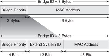
![]() To accommodate the extended system ID, the original 802.1D 16-bit bridge priority field is split into two fields, resulting in these components in the BID, as shown in Figure 3-12:
To accommodate the extended system ID, the original 802.1D 16-bit bridge priority field is split into two fields, resulting in these components in the BID, as shown in Figure 3-12:
-
 Bridge priority: A 4-bit field still used to carry bridge priority. Because of the limited bit count, the priority is conveyed in discreet values in increments of 4096 rather than discreet values in increments of 1, as they would be if the full 16-bit field was available. The default priority, in accordance with IEEE 802.1D, is 32,768, which is the midrange value.
 -
 Extended system ID: A 12-bit field carrying, in this case, the VID for PVST+.
 -
 MAC address: A 6-byte field with the MAC address of a single switch.
![]() By virtue of the MAC address, a BID is always unique. When the priority and extended system ID are prepended to the switch MAC address, each VLAN on the switch can be represented by a unique BID.
By virtue of the MAC address, a BID is always unique. When the priority and extended system ID are prepended to the switch MAC address, each VLAN on the switch can be represented by a unique BID.
![]() If no priority has been configured, every switch will have the same default priority, and the election of the root for each VLAN is based on the MAC address. This method is a random means of selecting the ideal root bridge; for this reason, it is advisable to assign a lower priority to the switch that should serve as the root bridge.
If no priority has been configured, every switch will have the same default priority, and the election of the root for each VLAN is based on the MAC address. This method is a random means of selecting the ideal root bridge; for this reason, it is advisable to assign a lower priority to the switch that should serve as the root bridge.
![]() Only four high-order bits of the 16-bit Bridge Priority field carry actual priority. Therefore, priority can be incremented only in steps of 4096, onto which are added the VLAN number, as shown in Table 3-7. For example, for VLAN 11: If the priority is left at default, the 16-bit Priority field will hold 32768 + 11 = 32779.
Only four high-order bits of the 16-bit Bridge Priority field carry actual priority. Therefore, priority can be incremented only in steps of 4096, onto which are added the VLAN number, as shown in Table 3-7. For example, for VLAN 11: If the priority is left at default, the 16-bit Priority field will hold 32768 + 11 = 32779.
|
|
|
|---|---|
|
|
|
|
|
|
|
|
|
|
|
|
|
|
|
|
|
|
|
|
|
 Compatibility with 802.1D
![]() RSTP can operate with legacy STPs. However, it is important to note that 802.1w’s inherent fast-convergence benefits are lost when interacting with legacy bridges.
RSTP can operate with legacy STPs. However, it is important to note that 802.1w’s inherent fast-convergence benefits are lost when interacting with legacy bridges.
![]() Each port maintains a variable that defines the protocol to run on the corresponding segment. If the port consistently keeps receiving BPDUs that do not correspond to its current operating mode for two times the hello time, it switches to the other STP mode.
Each port maintains a variable that defines the protocol to run on the corresponding segment. If the port consistently keeps receiving BPDUs that do not correspond to its current operating mode for two times the hello time, it switches to the other STP mode.
 Cisco Spanning Tree Default Configuration
![]() Cisco Catalyst switches support three types of spanning tree:
Cisco Catalyst switches support three types of spanning tree:
-
 PVST+
PVST+ -
 PVRST+
 -
 MST
MST
![]() The default spanning tree mode for Cisco Catalyst switches is PVST+. In this mode, a separate STP instance runs for each VLAN. The direct consequence is that, as the STP calculation is done the same way for each VLAN, the same switch becomes root bridge for all VLANs. Each change of topology has exactly the same impact on all VLANs. Redundant links are blocked the same way, at the same location of the network. There is no load sharing between redundant links in this configuration.
The default spanning tree mode for Cisco Catalyst switches is PVST+. In this mode, a separate STP instance runs for each VLAN. The direct consequence is that, as the STP calculation is done the same way for each VLAN, the same switch becomes root bridge for all VLANs. Each change of topology has exactly the same impact on all VLANs. Redundant links are blocked the same way, at the same location of the network. There is no load sharing between redundant links in this configuration.
 PortFast
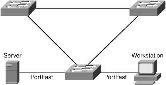
![]() Spanning Tree PortFast causes an interface configured as a Layer 2 access port to enter the forwarding state immediately, bypassing the listening and learning states. Enable PortFast on Layer 2 access ports connected to a single workstation or server to allow those devices to connect to the network immediately, rather than waiting for spanning tree to converge. In Figure 3-13, a server and workstation are attached to an access switch through ports that have the PortFast feature enabled.
Spanning Tree PortFast causes an interface configured as a Layer 2 access port to enter the forwarding state immediately, bypassing the listening and learning states. Enable PortFast on Layer 2 access ports connected to a single workstation or server to allow those devices to connect to the network immediately, rather than waiting for spanning tree to converge. In Figure 3-13, a server and workstation are attached to an access switch through ports that have the PortFast feature enabled.
![]() Figure 3-13 illustrates the modification in the STP state machine for interfaces configured for the PortFast feature. As illustrated in the figure, the STP state jumps directly from blocking to forwarding without going through the listening and learning state. In addition, PortFast suppresses topology change notifications.
Figure 3-13 illustrates the modification in the STP state machine for interfaces configured for the PortFast feature. As illustrated in the figure, the STP state jumps directly from blocking to forwarding without going through the listening and learning state. In addition, PortFast suppresses topology change notifications.
| Note |
|
 Configuring the PortFast Feature
![]() On Cisco IOS–based Catalyst switches, use the following interface command to enable or disable the PortFast feature:
On Cisco IOS–based Catalyst switches, use the following interface command to enable or disable the PortFast feature:
[no] spanning-tree portfast
![]() Example 3-1 illustrates a user configuring the PortFast feature and verifying the configuration.
Example 3-1 illustrates a user configuring the PortFast feature and verifying the configuration.
Switch# configure terminal
Enter configuration commands, one per line. End with CNTL/Z.
Switch(config)# interface FastEthernet 3/27
Switch(config-if)# spanning-tree portfast
%Warning: portfast should only be enabled on ports connected to a single
host. Connecting hubs, concentrators, switches, bridges, etc... to this
interface  when portfast is enabled, can cause temporary bridging loops.
Use with CAUTION

%Portfast has been configured on FastEthernet3/27 but will only
have effect when the interface is in a non-trunking mode.
Switch(config-if)# end
Switch#
Switch# show spanning-tree interface FastEthernet 3/27 portfast
VLAN0001         enabled
![]() On building access switches, enable PortFast globally so that there is no need to explicitly enable PortFast on each port individually. Remember to explicitly disable PortFast on uplink ports that connect to distribution layer switches. Enabling Portfast globally affects only the access ports and does not affect trunk ports. Use the interface level command spanning-tree portfast trunk to enable portfast on trunk port.
On building access switches, enable PortFast globally so that there is no need to explicitly enable PortFast on each port individually. Remember to explicitly disable PortFast on uplink ports that connect to distribution layer switches. Enabling Portfast globally affects only the access ports and does not affect trunk ports. Use the interface level command spanning-tree portfast trunk to enable portfast on trunk port.
![]() Use the following command to enable PortFast globally in global configuration mode:
Use the following command to enable PortFast globally in global configuration mode:
spanning-tree portfast default
![]() PortFast is a highly recommended configuration on end-user ports and server ports along with disabling negotiation of channeling and trunking. The end result of these configurations is to enable immediate forwarding frames on link up. On Cisco IOS-based Catalyst switches, use the following command to place an interface into this desired configuration:
PortFast is a highly recommended configuration on end-user ports and server ports along with disabling negotiation of channeling and trunking. The end result of these configurations is to enable immediate forwarding frames on link up. On Cisco IOS-based Catalyst switches, use the following command to place an interface into this desired configuration:
switchport mode host
![]() Example 3-2 shows a user configuring an interface for connecting to a host.
Example 3-2 shows a user configuring an interface for connecting to a host.
SwitchB# configure terminal
Enter configuration commands, one per line.  End with CNTL/Z.
SwitchB(config)# interface fastEthernet 3/9
SwitchB(config-if)# switchport host
switchport mode will be set to access
spanning-tree portfast will be enabled
channel group will be disabled
SwitchB(config-if)# end
SwitchB#
 Configuring the Basic Parameters of PVRST+
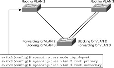
![]() To implement PVRST+, perform these steps:
To implement PVRST+, perform these steps:
-
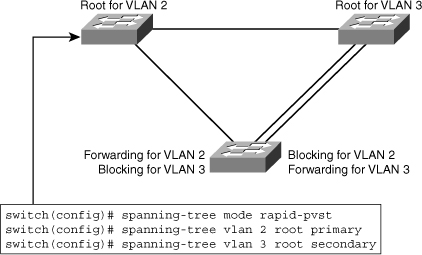
 Enable PVRST+ globally. PVRST+ should be configured on all switches in the broadcast domain, as shown in Figure 3-14.
 -
 Designate and configure a switch to be the root bridge.
 -
 Designate and configure a switch to be the secondary (backup) root bridge.
 -
 Enable load sharing on uplinks using priority and cost parameters.
 -
 Verify the configuration.
![]() Example 3-3 illustrates how to display the RSTP information for VLAN2 on a nonroot switch in topology, as shown in Figure 3-14.
Example 3-3 illustrates how to display the RSTP information for VLAN2 on a nonroot switch in topology, as shown in Figure 3-14.
Cat6503E# show spanning-tree vlan 2

VLAN0002
Spanning tree enabled protocol rstp
Root ID    Priority    32768
            Address     000b.fcb5.dac0
            Cost        38
            Port        7 (FastEthernet0/7)
            Hello Time  2 sec  Max Age 20 sec  Forward Delay 15 sec

Bridge ID  Priority    32770  (priority 32768 sys-id-ext 2)
            Address     0013.5f1c.e1c0
            Hello Time   2 sec  Max Age 20 sec  Forward Delay 15 sec
            Aging Time 300

Interface            Role Sts Cost      Prio.Nbr Type
------------------- ---- --- --------- -------- --------------------------------
Fa0/7                Root FWD 19         128.7    P2p
Fa0/8                Root FWD 19         128.8    P2p
Multiple Spanning Tree
![]() Multiple Spanning Tree (MST) extends the IEEE 802.1w RST algorithm to multiple spanning trees. The main purpose of MST is to reduce the total number of spanning-tree instances to match the physical topology of the network and thus reduce the CPU cycles of a switch. PVRST+ runs STP instances for each VLAN and does not take into consideration the physical topology that might not require many different STP topologies. MST, on the other hand, uses a minimum number of STP instances to match the number of physical topologies present.
Multiple Spanning Tree (MST) extends the IEEE 802.1w RST algorithm to multiple spanning trees. The main purpose of MST is to reduce the total number of spanning-tree instances to match the physical topology of the network and thus reduce the CPU cycles of a switch. PVRST+ runs STP instances for each VLAN and does not take into consideration the physical topology that might not require many different STP topologies. MST, on the other hand, uses a minimum number of STP instances to match the number of physical topologies present.
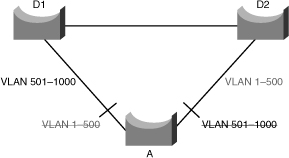
![]() Figure 3-15 shows a common network design, featuring an access Switch A, connected to two Building Distribution submodule Switches D1 and D2. In this setup, there are 1000 VLANs, and the network administrator typically seeks to achieve load balancing on the access switch uplinks based on even or odd VLANs—or any other scheme deemed appropriate.
Figure 3-15 shows a common network design, featuring an access Switch A, connected to two Building Distribution submodule Switches D1 and D2. In this setup, there are 1000 VLANs, and the network administrator typically seeks to achieve load balancing on the access switch uplinks based on even or odd VLANs—or any other scheme deemed appropriate.
![]() Figure 3-15 illustrates two links and 1000 VLANs. The 1000 VLANs map to two MST instances. Rather than maintaining 1000 spanning trees, each switch needs to maintain only two spanning trees, reducing the need for switch resources. This concept of two MST instances for the topology, as shown in Figure 3-15, extends to 4096 VLANs. MST converges faster than PVRST+ and is backward compatible with 802.1D STP, 802.1w (RSTP), and the Cisco PVSTP+ architecture.
Figure 3-15 illustrates two links and 1000 VLANs. The 1000 VLANs map to two MST instances. Rather than maintaining 1000 spanning trees, each switch needs to maintain only two spanning trees, reducing the need for switch resources. This concept of two MST instances for the topology, as shown in Figure 3-15, extends to 4096 VLANs. MST converges faster than PVRST+ and is backward compatible with 802.1D STP, 802.1w (RSTP), and the Cisco PVSTP+ architecture.
![]() MST allows for the building of multiple spanning trees over trunks by grouping and associating VLANs to spanning-tree instances. Each instance may have a topology that is independent of other spanning-tree instances. This architecture provides multiple forwarding paths for data traffic and enables load balancing. A failure in one forwarding path does not affect other instances with different forwarding paths; hence, this architecture improves network fault tolerance.
MST allows for the building of multiple spanning trees over trunks by grouping and associating VLANs to spanning-tree instances. Each instance may have a topology that is independent of other spanning-tree instances. This architecture provides multiple forwarding paths for data traffic and enables load balancing. A failure in one forwarding path does not affect other instances with different forwarding paths; hence, this architecture improves network fault tolerance.
![]() In large networks, using different VLANs and a different spanning-tree topology enables better administration of the network and use of the redundant paths available. An MST spanning-tree instance might exist only on bridges that have compatible VLAN instance assignments. Configuring a set of bridges with the same MST configuration information allows them to participate in a specific set of spanning-tree instances. The term MST region refers to the set of interconnected bridges that have the same MST configuration.
In large networks, using different VLANs and a different spanning-tree topology enables better administration of the network and use of the redundant paths available. An MST spanning-tree instance might exist only on bridges that have compatible VLAN instance assignments. Configuring a set of bridges with the same MST configuration information allows them to participate in a specific set of spanning-tree instances. The term MST region refers to the set of interconnected bridges that have the same MST configuration.
![]() Implementation of MST is not required if the Enterprise Campus Model is being employed because the number of active VLAN instances, and hence the STP instances, would be small and stable due to the design.
Implementation of MST is not required if the Enterprise Campus Model is being employed because the number of active VLAN instances, and hence the STP instances, would be small and stable due to the design.
![]() In the scenario described in Figure 3-15, only two different final logical topologies exist and therefore require only two spanning-tree instances. There is no need to run 1000 instances if, as shown in Figure 3-15, half of the 1000 VLANs map to a different spanning-tree instance.
In the scenario described in Figure 3-15, only two different final logical topologies exist and therefore require only two spanning-tree instances. There is no need to run 1000 instances if, as shown in Figure 3-15, half of the 1000 VLANs map to a different spanning-tree instance.
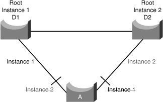
![]() In a network running MST, as depicted in Figure 3-16, the following is true:
In a network running MST, as depicted in Figure 3-16, the following is true:
-
 The desired load-balancing scheme is still possible because half the VLANs follow one separate instance.
 -
 The switch utilization is low because it has to handle only two instances.
![]() From a technical standpoint, MST is the best solution for the scenario presented in Figure 3-16. Because MST is a newer protocol, however, the following issues could arise:
From a technical standpoint, MST is the best solution for the scenario presented in Figure 3-16. Because MST is a newer protocol, however, the following issues could arise:
-
 The protocol is more complex than the usual spanning tree and thus requires additional training of the operation staff.
 -
 Interaction with legacy bridges is sometimes challenging.
![]() MST enables you to build multiple spanning trees over trunks by grouping VLANs and associating them with spanning-tree instances. Each instance can have a topology independent of other spanning-tree instances. This architecture provides multiple active forwarding paths for data traffic and enables load balancing.
MST enables you to build multiple spanning trees over trunks by grouping VLANs and associating them with spanning-tree instances. Each instance can have a topology independent of other spanning-tree instances. This architecture provides multiple active forwarding paths for data traffic and enables load balancing.
![]() Network fault tolerance is improved over Common Spanning Tree (CST) because a failure in one instance (forwarding path) does not necessarily affect other instances. This VLAN-to-MST grouping must be consistent across all bridges within an MST region.
Network fault tolerance is improved over Common Spanning Tree (CST) because a failure in one instance (forwarding path) does not necessarily affect other instances. This VLAN-to-MST grouping must be consistent across all bridges within an MST region.
![]() In large networks, you can more easily administer the network and use redundant paths by locating different VLAN and spanning-tree assignments in different parts of the network. A spanning-tree instance can exist only on bridges that have compatible VLAN instance assignments.
In large networks, you can more easily administer the network and use redundant paths by locating different VLAN and spanning-tree assignments in different parts of the network. A spanning-tree instance can exist only on bridges that have compatible VLAN instance assignments.
![]() You must configure a set of bridges with the same MST configuration information, which allows them to participate in a specific set of spanning-tree instances. Interconnected bridges that have the same MST configuration are referred to as an MST region. Bridges with different MST configurations or legacy bridges running 802.1D are considered separate MST regions.
You must configure a set of bridges with the same MST configuration information, which allows them to participate in a specific set of spanning-tree instances. Interconnected bridges that have the same MST configuration are referred to as an MST region. Bridges with different MST configurations or legacy bridges running 802.1D are considered separate MST regions.
 MST Regions
![]() The main enhancement introduced by MST is the ability to map several VLANs to a single spanning-tree instance. This raises the problem, however, of determining what VLAN is to be associated with what instance. More precisely, based on received BPDUs, devices need to identify these instances and the VLANs that are mapped to the instances.
The main enhancement introduced by MST is the ability to map several VLANs to a single spanning-tree instance. This raises the problem, however, of determining what VLAN is to be associated with what instance. More precisely, based on received BPDUs, devices need to identify these instances and the VLANs that are mapped to the instances.
![]() In the case of the 802.1Q standard, all instances map to a unique and common instance and are therefore less complex. In the case of PVST+, each VLAN carries the BPDUs for its respective instance (one BPDU per VLAN).
In the case of the 802.1Q standard, all instances map to a unique and common instance and are therefore less complex. In the case of PVST+, each VLAN carries the BPDUs for its respective instance (one BPDU per VLAN).
![]() Each switch that runs MST in the network has a single MST configuration that consists of three attributes:
Each switch that runs MST in the network has a single MST configuration that consists of three attributes:
-
 An alphanumeric configuration name (32 bytes)
 -
 A configuration revision number (2 bytes)
 -
 A 4096-element table that associates each of the potential 4096 VLANs supported on the chassis to a given instance
![]() To be part of a common MST region, a group of switches must share the same configuration attributes. It is up to the network administrator to properly propagate the configuration throughout the region.
To be part of a common MST region, a group of switches must share the same configuration attributes. It is up to the network administrator to properly propagate the configuration throughout the region.
![]() To ensure a consistent VLANs-to-instance mapping, the protocol must exactly identify the boundaries of the regions. For that purpose, the characteristics of the region are included in BPDUs. Switches do not propagate the exact VLANs-to-instance mapping in the BPDU because the switches need to know only whether they are in the same region as a neighbor. Therefore, switches only send a digest of the VLANs-to-instance mapping table, along with the revision number and the name. When a switch receives a BPDU, it extracts the message digest, a numerical value derived from the VLANs-to-instance mapping table through a mathematical function, and compares it with its own computed digest. If the digests differ, the port receiving the BPDU is at the boundary of a region.
To ensure a consistent VLANs-to-instance mapping, the protocol must exactly identify the boundaries of the regions. For that purpose, the characteristics of the region are included in BPDUs. Switches do not propagate the exact VLANs-to-instance mapping in the BPDU because the switches need to know only whether they are in the same region as a neighbor. Therefore, switches only send a digest of the VLANs-to-instance mapping table, along with the revision number and the name. When a switch receives a BPDU, it extracts the message digest, a numerical value derived from the VLANs-to-instance mapping table through a mathematical function, and compares it with its own computed digest. If the digests differ, the port receiving the BPDU is at the boundary of a region.
![]() In generic terms, a port is at the boundary of a region if the designated bridge on its segment is in a different region or if it receives legacy 802.1D BPDUs. In Figure 3-17, the port on B1 is at the boundary of Region A, whereas the ports on B2 and B3 are internal to Region B.
In generic terms, a port is at the boundary of a region if the designated bridge on its segment is in a different region or if it receives legacy 802.1D BPDUs. In Figure 3-17, the port on B1 is at the boundary of Region A, whereas the ports on B2 and B3 are internal to Region B.
 Extended System ID for MST
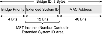
![]() As with PVRST+, the 12-bit Extended System ID field is used in MST, as shown in Figure 3-18. In MST, this field carries the MST instance number.
As with PVRST+, the 12-bit Extended System ID field is used in MST, as shown in Figure 3-18. In MST, this field carries the MST instance number.
 Configuring MST
![]() Enabling MST is a multistep process that involves mapping ranges of VLANs to a single MSTI.
Enabling MST is a multistep process that involves mapping ranges of VLANs to a single MSTI.
![]() Because MST is applicable to multiple VLANs, it requires some additional configuration beyond that needed for PVRST+. After you enable MST with the command spanning-tree mode mst, you must configure regions and instances with additional configuration commands.
Because MST is applicable to multiple VLANs, it requires some additional configuration beyond that needed for PVRST+. After you enable MST with the command spanning-tree mode mst, you must configure regions and instances with additional configuration commands.
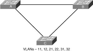
![]() Consider Figure 3-19 with three switches with six VLANs that need to be implemented. Spanning tree must be configured across these three switches. The Switches A and B are distribution switches. Either of them would be a possible candidate to perform the root bridge role.
Consider Figure 3-19 with three switches with six VLANs that need to be implemented. Spanning tree must be configured across these three switches. The Switches A and B are distribution switches. Either of them would be a possible candidate to perform the root bridge role.
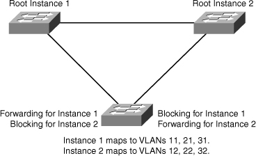
![]() A possible solution is to use MST with two instances, each instance grouping half the needed VLANs. Switch A would be the root for the first instance with odd VLANs assigned to it, Switch B would be the root for the second instance with even VLANs assigned to it.
A possible solution is to use MST with two instances, each instance grouping half the needed VLANs. Switch A would be the root for the first instance with odd VLANs assigned to it, Switch B would be the root for the second instance with even VLANs assigned to it.
![]() Table 3-8 shows the various steps involved in configuring MST in a network, and Example 3-4 shows a user configuring Switches A and B to reflect the final configuration, as shown in Figure 3-20. Switch A is configured root for instance 1 and Switch B is configured root for instance 2, but the rest of the configuration, including name and VLAN grouping to instances, are identical.
Table 3-8 shows the various steps involved in configuring MST in a network, and Example 3-4 shows a user configuring Switches A and B to reflect the final configuration, as shown in Figure 3-20. Switch A is configured root for instance 1 and Switch B is configured root for instance 2, but the rest of the configuration, including name and VLAN grouping to instances, are identical.
|
|
|
|
|---|---|---|
|
|
|
|
|
|
|
|
|
| ||
|
|
|
|
|
|
|
|
|
|
|
|
|
|
|
|
|
|
|
|
|
|
|
|
|
|
|
|
SwitchA(config)# spanning-tree mode mst
SwitchA(config)# spanning-tree mst configuration
SwitchA(config-mst)# name XYZ
SwitchA(config-mst)# revision 1
SwitchA(config-mst)# instance 1 vlan 11, 21, 31
SwitchA(config-mst)# instance 2 vlan 12, 22,32
SwitchA(config)# spanning-tree mst 1 root primary
SwitchB(config)# spanning-tree mode mst
SwitchB(config)# spanning-tree mst configuration
SwitchB(config-mst)# name XYZ
SwitchB(config-mst)# revision 1
SwitchB(config-mst)# instance 1 vlan 11, 21, 31
SwitchB(config-mst)# instance 2 vlan 12, 22,32
SwitchB(config)# spanning-tree mst 2 root primary
![]() Example 3-5 illustrates a user changing the spanning-tree mode to MST and configuring the MST region by mapping the range of VLANs to Instance 1.
Example 3-5 illustrates a user changing the spanning-tree mode to MST and configuring the MST region by mapping the range of VLANs to Instance 1.
Switch# configure terminal
Enter configuration commands, one per line.  End with CNTL/Z.
Switch(config)# spanning-tree mode mst
Switch(config)# spanning-tree mst configuration
Switch(config-mst)# show current
Current MST configuration
Name      []
Revision  0
Instance  Vlans mapped
--------  -----------------------------------------------------------
0         1-4094
---------------------------------------------------------------------
Switch(config-mst)#  name cisco
Switch(config-mst)#  revision 1
Switch(config-mst)#  instance 1 vlan 1-10
Switch(config-mst)#  show pending
Pending MST configuration
Name       [cisco]
Revision  1
Instance  Vlans mapped
--------  -----------------------------------------------------------
0          11-4094
1          1-10
Switch(config-mst)# end
![]() The show current command in Example 3-5 displays the current MST configuration on the switch. The show pending command details the uncommitted MST configuration. Catalyst switches discard the pending configuration if the administrator aborts the configuration changes by using the abort command. In addition, Catalyst switches save the MST configuration when issuing the end command, as shown in Example 3-5.
The show current command in Example 3-5 displays the current MST configuration on the switch. The show pending command details the uncommitted MST configuration. Catalyst switches discard the pending configuration if the administrator aborts the configuration changes by using the abort command. In addition, Catalyst switches save the MST configuration when issuing the end command, as shown in Example 3-5.
![]() Example 3-6 illustrates a user displaying MST protocol information for MSTIs configured on the switch.
Example 3-6 illustrates a user displaying MST protocol information for MSTIs configured on the switch.
Switch# show spanning-tree mst
###### MST00        vlans mapped:   5-4094
Bridge      address 0009.e845.6480  priority  32768 (32768 sysid 0)
Root        this switch for CST and IST
Configured  hello time 2, forward delay 15, max age 20, max hops 20

Interface         Role Sts Cost      Prio.Nbr Type
---------------- ---- --- --------- -------- --------------------------------
Fa3/24            Desg FWD 2000000   128.152  Shr
Fa3/32            Desg FWD 200000    128.160  P2p
Fa3/42            Back BLK 200000    128.170  P2p

###### MST01         vlans mapped:   1-2
Bridge       address 0009.e845.6480  priority  32769 (32768 sysid 1)
Root        this switch for MST01
Interface         Role Sts Cost      Prio.Nbr Type
---------------- ---- --- --------- -------- --------------------------------
Fa3/24            Desg FWD 2000000   128.152  Shr
Fa3/32            Desg FWD 200000    128.160  P2p
Fa3/42            Back BLK 200000    128.170  P2p
###### MST02         vlans mapped:   3-4
Bridge       address 0009.e845.6480  priority  32770 (32768 sysid 2)
Root         this switch for MST02
Interface         Role Sts Cost      Prio.Nbr Type
---------------- ---- --- --------- -------- --------------------------------
Fa3/24            Desg FWD 2000000   128.152  Shr
![]() Example 3-7 illustrates a user displaying MST protocol information for a specific MSTI.
Example 3-7 illustrates a user displaying MST protocol information for a specific MSTI.
Switch# show spanning-tree mst 1

###### MST01        vlans mapped:   1-2
Bridge      address 0009.e845.6480  priority  32769 (32768 sysid 1)
Root        this switch for MST01

Interface        Role Sts Cost      Prio.Nbr Type
---------------- ---- --- --------- -------- --------------------------------
Fa3/24           Desg FWD 2000000   128.152  Shr
Fa3/32           Desg FWD 200000    128.160  P2p
Fa3/42           Back BLK 200000    128.170  P2p
![]() Example 3-8 illustrates a user displaying MST protocol information for a specific interface.
Example 3-8 illustrates a user displaying MST protocol information for a specific interface.
Switch# show spanning-tree mst interface FastEthernet 3/24

FastEthernet3/24 of MST00 is designated forwarding
Edge port: no              (default)        port guard : none        (default)
Link type: shared          (auto)           bpdu filter: disable    (default)
Boundary : internal                         bpdu guard : disable     (default)
Bpdus sent 81, received 81

Instance Role Sts Cost      Prio.Nbr Vlans mapped
-------- ---- --- --------- -------- -------------------------------
0        Desg FWD 2000000    128.152  5-4094
1        Desg FWD 2000000    128.152  1-2
2        Desg FWD 2000000    128.152  3-4
![]() Example 3-9 illustrates a user displaying detailed information for a specific instance.
Example 3-9 illustrates a user displaying detailed information for a specific instance.
Switch# show spanning-tree mst 1 detail

###### MST01         vlans mapped:    1-2
Bridge       address 0009.e845.6480  priority  32769 (32768 sysid 1)
Root         this switch for MST01
FastEthernet3/24 of MST01 is designated forwarding
Port info             port id        128.152  priority    128  cost     2000000
Designated root       address 0009.e845.6480  priority  32769  cost           0
Designated bridge     address 0009.e845.6480  priority  32769  port id  128.152
Timers: message expires in 0 sec, forward delay 0, forward transitions 1
Bpdus (MRecords) sent755, received 0

FastEthernet3/32 of MST01 is designated forwarding
Port info             port id        128.160  priority    128  cost      200000
Designated root       address 0009.e845.6480  priority  32769  cost           0
Designated bridge     address 0009.e845.6480  priority  32769  port id  128.160
Timers: message expires in 0 sec, forward delay 0, forward transitions 1
Bpdus (MRecords) sent 769, received 1

FastEthernet3/42 of MST01 is backup blocking
Port info             port id        128.170  priority    128  cost      200000
Designated root       address 0009.e845.6480  priority  32769  cost           0
Designated bridge     address 0009.e845.6480  priority  32769  port id  128.160
Timers: message expires in 5 sec, forward delay 0, forward transitions 0
Bpdus (MRecords) sent 1, received 769



0 comments
Post a Comment