
Configuring and Verifying Basic OSPF Routing
![]() This section discusses the basic OSPF configuration and verification of single-area and multiarea OSPF networks.
This section discusses the basic OSPF configuration and verification of single-area and multiarea OSPF networks.
![]() The following topics are discussed:
The following topics are discussed:
 Planning and Configuring OSPF
![]() This section describes how to plan and configure basic OSPF and provides some detailed examples.
This section describes how to plan and configure basic OSPF and provides some detailed examples.
Planning OSPF Routing Implementations
![]() This section describes how to plan, implement, and document an OSPF deployment.
This section describes how to plan, implement, and document an OSPF deployment.
![]() When preparing to deploy OSPF routing in a network, the existing network state and requirements first need to be gathered, and deployment options considered. Considerations for OSPF include the following:
When preparing to deploy OSPF routing in a network, the existing network state and requirements first need to be gathered, and deployment options considered. Considerations for OSPF include the following:
- IP addressing plan— The IP addressing plan governs how OSPF can be deployed and how well the OSPF deployment will scale. A detailed hierarchical IP subnet and addressing plan must be produced, to enable OSPF summarization, allow the network to scale more easily, and to optimize OSPF behavior.
- Network topology— The topology consists of the devices (routers, switches, and so on) and the links connecting them. A detailed network topology should be created to assess OSPF scalability requirements and to determine which OSPF features might be required (for example, multiple areas, OSPF summarization, stub areas, and redistribution). The topology should include backup links where necessary.
- OSPF areas— Dividing an OSPF network into areas decreases the LSDB size and limits the propagation of link-state updates when the topology changes. The routers that are to be ABRs and ASBRs must be identified, as are those that are to perform any summarization or redistribution.
![]() After the requirements have been assessed, the implementation plan can be created. The implementation plan should include the following steps:
After the requirements have been assessed, the implementation plan can be created. The implementation plan should include the following steps:
- Gather the required parameters
- Define the OSPF routing parameters
- Configure OSPF
- Verify the OSPF configuration
![]() The information necessary to implement OSPF routing includes the following:
The information necessary to implement OSPF routing includes the following:
- The IP addresses to be configured on individual router interfaces.
- A list of routers on which OSPF is to be enabled, along with the OSPF process number to use and the connected networks that are to run OSPF and that need to be advertised (per individual router).
- The area in which each interface is to be configured.
- Metrics that need to be applied to specific interfaces, to influence the OSPF best path selection. The required metric and the interface where the metric needs to be applied should be specified.
![]() In the implementation plan, the list of tasks for each router in the network must be defined. For OSPF, the tasks include the following:
In the implementation plan, the list of tasks for each router in the network must be defined. For OSPF, the tasks include the following:
- Enabling the OSPF routing protocol, directly on an interface or by using the correct network command under the OSPF routing process configuration mode.
- Assigning the correct area id to the interface, via the OSPF configuration on the interface or under the OSPF routing process configuration mode.
- Optionally configuring the metric to appropriate interfaces.
![]() After implementing OSPF, proper deployment on each router should be verified. Verification tasks include the following:
After implementing OSPF, proper deployment on each router should be verified. Verification tasks include the following:
- Verifying that the appropriate OSPF neighbor relationships and adjacencies are established
- Verifying that the OSPF LSDB is populated with the necessary information
- Verifying that IP routing table is populated with the necessary information
- Verifying that there is connectivity in the network between routers and to other devices
- Verifying that OSPF behaves as expected in a case of a topology change, by testing link failure and router failure events
![]() After a successful OSPF deployment, the solution and verification process and results should be documented for future reference. Documentation should include a topology map, the IP addressing plan, the area hierarchy, the networks and interfaces included in OSPF on each router, the default and any special metrics configured, and the verification results.
After a successful OSPF deployment, the solution and verification process and results should be documented for future reference. Documentation should include a topology map, the IP addressing plan, the area hierarchy, the networks and interfaces included in OSPF on each router, the default and any special metrics configured, and the verification results.
Configuring Basic OSPF
![]() This section describes how you can configure OSPF using the router ospf command with network area commands under it, or directly on router interfaces with the ip ospf area command.
This section describes how you can configure OSPF using the router ospf command with network area commands under it, or directly on router interfaces with the ip ospf area command.
![]() To configure the OSPF process, do the following:
To configure the OSPF process, do the following:
|
|
|
|
|
|
|---|---|
|
|
|
|
|
|
|
|
|
|
|
|
|---|---|
|
|
|
|
|
|
|
|
|
![]() Alternatively, starting with Cisco IOS Software Release 12.3(11)T (and some specific versions of earlier releases), OSPF can be enabled directly on the interface using the ip ospf process-id area area-id [secondaries none] interface configuration command. This command simplifies the configuration of unnumbered interfaces. Because this command is configured explicitly for the interface, it takes precedence over the network area command. Table 3-5 describes the parameters of the ip ospf area command.
Alternatively, starting with Cisco IOS Software Release 12.3(11)T (and some specific versions of earlier releases), OSPF can be enabled directly on the interface using the ip ospf process-id area area-id [secondaries none] interface configuration command. This command simplifies the configuration of unnumbered interfaces. Because this command is configured explicitly for the interface, it takes precedence over the network area command. Table 3-5 describes the parameters of the ip ospf area command.
|
|
|
|---|---|
|
|
|
|
|
|
|
|
|
| Note |
|
Single-Area OSPF Configuration Example
![]() Figure 3-14 shows the OSPF configuration for Fast Ethernet broadcast networks and serial point-to-point links, on two of the three routers. All three routers in Figure 3-14 are assigned to area 0 and are configured for network 10.0.0.0.
Figure 3-14 shows the OSPF configuration for Fast Ethernet broadcast networks and serial point-to-point links, on two of the three routers. All three routers in Figure 3-14 are assigned to area 0 and are configured for network 10.0.0.0.


![]() Router A uses a general network 10.0.0.0 0.255.255.255 statement. This technique assigns all interfaces defined in the 10.0.0.0 network to OSPF process 1.
Router A uses a general network 10.0.0.0 0.255.255.255 statement. This technique assigns all interfaces defined in the 10.0.0.0 network to OSPF process 1.
![]() Router B uses a specific host address technique. The wildcard mask of 0.0.0.0 matches all 4 bytes of the address. This technique allows the administrator to define which specific interfaces will run OSPF.
Router B uses a specific host address technique. The wildcard mask of 0.0.0.0 matches all 4 bytes of the address. This technique allows the administrator to define which specific interfaces will run OSPF.
![]() Although the two examples shown in Figure 3-14 are a commonly used combination of a network statement and a wildcard mask, others could also work. For instance, a range of subnets could be specified.
Although the two examples shown in Figure 3-14 are a commonly used combination of a network statement and a wildcard mask, others could also work. For instance, a range of subnets could be specified.
| Note |
|
Multiarea OSPF Configuration Example
![]() Figure 3-15 shows an example of multiarea OSPF configuration. Router A is in area 0, Router C is in area 1, and Router B is the ABR between the two areas.
Figure 3-15 shows an example of multiarea OSPF configuration. Router A is in area 0, Router C is in area 1, and Router B is the ABR between the two areas.


![]() The configuration for Router A is the same as it was in Figure 3-14.
The configuration for Router A is the same as it was in Figure 3-14.
![]() Router B has a network statement for area 0. The configuration for area 1 in this example uses the ip ospf 50 area 1 interface configuration command. Alternatively a separate network router configuration command, such as network 10.2.1.2 0.0.0.0 area 1, could have been used.
Router B has a network statement for area 0. The configuration for area 1 in this example uses the ip ospf 50 area 1 interface configuration command. Alternatively a separate network router configuration command, such as network 10.2.1.2 0.0.0.0 area 1, could have been used.
OSPF Router ID
![]() An OSPF router ID uniquely identifies each OSPF router in the network. The OSPF routing process chooses a router ID for itself when it starts up. The router ID is a unique number in IP address format that can be assigned in the following ways:
An OSPF router ID uniquely identifies each OSPF router in the network. The OSPF routing process chooses a router ID for itself when it starts up. The router ID is a unique number in IP address format that can be assigned in the following ways:
- By default, the highest IP address of any active physical interface when OSPF starts is chosen as the router ID. The interface does not have to be part of the OSPF process, but it has to be up. There must be at least one “up” IP interface on the router for OSPF to use as the router ID. If no up interface with an IP address is available when the OSPF process starts, the following error message occurs:R1(config)#router ospf 1
2w1d: %OSPF-4-NORTRID: OSPF process 1 cannot start. - Alternatively, if a loopback interface exists, its IP address will always be preferred as the router ID instead of the IP address of a physical interface, because a loopback interface never goes down. If there is more than one loopback interface, the highest IP address on any active loopback interface becomes the router ID.
- Alternatively, if the router-id ip-address OSPF router configuration command is used, it will override the use of the address of a physical or loopback interface as the router ID. Using the router-id command is the preferred procedure for setting the router ID.
![]() The OSPF database uses the router ID to uniquely describe each router in the network. Remember that every router keeps a complete topology database of all routers and links in an area and network. Therefore, router IDs should be unique throughout the OSPF autonomous system, no matter how they are configured.
The OSPF database uses the router ID to uniquely describe each router in the network. Remember that every router keeps a complete topology database of all routers and links in an area and network. Therefore, router IDs should be unique throughout the OSPF autonomous system, no matter how they are configured.
![]() After the router ID has been set, it does not change, even if the interface that the router is using for the router ID goes down. The OSPF router ID changes only if the router reloads or if the OSPF routing process restarts.
After the router ID has been set, it does not change, even if the interface that the router is using for the router ID goes down. The OSPF router ID changes only if the router reloads or if the OSPF routing process restarts.
![]() If a physical interface address is being used as the router ID, and that physical interface fails, and the router (or OSPF process) is restarted, the router ID will change. This change in router ID makes it more difficult for network administrators to troubleshoot and manage OSPF. The stability provided by using a loopback interface for the router ID or by using the router-id command comes from the router ID staying the same, regardless of the state of the physical interfaces.
If a physical interface address is being used as the router ID, and that physical interface fails, and the router (or OSPF process) is restarted, the router ID will change. This change in router ID makes it more difficult for network administrators to troubleshoot and manage OSPF. The stability provided by using a loopback interface for the router ID or by using the router-id command comes from the router ID staying the same, regardless of the state of the physical interfaces.
![]() The following sections describe how loopback interfaces are configured, and how the router ID is configured and verified.
The following sections describe how loopback interfaces are configured, and how the router ID is configured and verified.
Loopback Interfaces
![]() To allow OSPF to use a loopback address as the router ID, first define a loopback interface with the interface loopback number global configuration command, and then configure an IP address on the loopback interface.
To allow OSPF to use a loopback address as the router ID, first define a loopback interface with the interface loopback number global configuration command, and then configure an IP address on the loopback interface.
![]() As mentioned, configuring an IP address on a loopback interface overrides the highest IP address on any active physical interface being used as the router ID. OSPF is more stable if a loopback interface address is used, rather than a physical interface address, because the loopback interface is always active and cannot fail, whereas a real interface could go down. For this reason, you should use a loopback address on all key routers (unless the router-id command is used).
As mentioned, configuring an IP address on a loopback interface overrides the highest IP address on any active physical interface being used as the router ID. OSPF is more stable if a loopback interface address is used, rather than a physical interface address, because the loopback interface is always active and cannot fail, whereas a real interface could go down. For this reason, you should use a loopback address on all key routers (unless the router-id command is used).
![]() If the loopback address is advertised with the network command, then this address can be pinged for testing purposes, and used for management of the router and for the OSPF router ID. The IP address chosen for the loopback address can be either a private or public IP address, dictated by the network requirements (of course, if a private IP address is used it saves public IP address space).
If the loopback address is advertised with the network command, then this address can be pinged for testing purposes, and used for management of the router and for the OSPF router ID. The IP address chosen for the loopback address can be either a private or public IP address, dictated by the network requirements (of course, if a private IP address is used it saves public IP address space).
| Note |
|
OSPF router-id Command
![]() The router-id ip-address OSPF router configuration command ensures that OSPF selects a specific planned router ID. The ip-address parameter can be any unique arbitrary 32-bit value in an IP address format (dotted decimal).
The router-id ip-address OSPF router configuration command ensures that OSPF selects a specific planned router ID. The ip-address parameter can be any unique arbitrary 32-bit value in an IP address format (dotted decimal).
![]() After configuring the router-id command, use the clear ip ospf process EXEC command to restart the OSPF routing process, so the router reselects the new IP address as its router ID. For example, the commands shown in Example 3-3 ensure that OSPF selects the preconfigured router ID 172.16.1.1.
After configuring the router-id command, use the clear ip ospf process EXEC command to restart the OSPF routing process, so the router reselects the new IP address as its router ID. For example, the commands shown in Example 3-3 ensure that OSPF selects the preconfigured router ID 172.16.1.1.
| Caution |
|
Router(config-router)#router-id 172.16.1.1
Router#clear ip ospf process
| Note |
|
Verifying the OSPF Router ID
![]() Use the show ip ospf command to verify the OSPF router ID. This command also displays OSPF timer settings and other statistics, including the number of times the SPF algorithm has been executed. Optional parameters allow you to specify other information to be displayed.
Use the show ip ospf command to verify the OSPF router ID. This command also displays OSPF timer settings and other statistics, including the number of times the SPF algorithm has been executed. Optional parameters allow you to specify other information to be displayed.
![]() Example 3-4 shows example output from this command when executed on Router B in Figure 3-15.
Example 3-4 shows example output from this command when executed on Router B in Figure 3-15.
Routing Process "ospf 50" with ID 10.64.0.2
Supports only single TOS(TOS0) routes
Supports opaque LSA
Supports Link-local Signaling (LLS)
Supports area transit capability
It is an area border router
Initial SPF schedule delay 5000 msecs
Minimum hold time between two consecutive SPFs 10000 msecs
Maximum wait time between two consecutive SPFs 10000 msecs
Incremental-SPF disabled
Minimum LSA interval 5 secs
Minimum LSA arrival 1000 msecs
LSA group pacing timer 240 secs
Interface flood pacing timer 33 msecs
Retransmission pacing timer 66 msecs
Number of external LSA 0. Checksum Sum 0x000000
Number of opaque AS LSA 0. Checksum Sum 0x000000
Number of DCbitless external and opaque AS LSA 0
Number of DoNotAge external and opaque AS LSA 0
Number of areas in this router is 2. 2 normal 0 stub 0 nssa
Number of areas transit capable is 0
External flood list length 0
Area BACKBONE(0)
Area BACKBONE(0)
Area has no authentication
SPF algorithm last executed 00:01:25.028 ago
SPF algorithm executed 7 times
Area ranges are
Number of LSA 6. Checksum Sum 0x01FE3E
Number of opaque link LSA 0. Checksum Sum 0x000000
Number of DCbitless LSA 0
Number of indication LSA 0
Number of DoNotAge LSA 0
Flood list length 0
Area 1
Number of interfaces in this area is 1
Area has no authentication
SPF algorithm last executed 00:00:54.636 ago
SPF algorithm executed 3 times
Area ranges are
Number of LSA 4. Checksum Sum 0x01228A
Number of opaque link LSA 0. Checksum Sum 0x000000
Number of DCbitless LSA 0
Number of indication LSA 0
Number of DoNotAge LSA 0
Flood list length 0
RouterB#
Verifying OSPF Operations
![]() To verify that OSPF has been properly configured, use the following show commands:
To verify that OSPF has been properly configured, use the following show commands:
- The show ip ospf command displays the OSPF router ID, OSPF timers, the number of times the SPF algorithm has been executed, and LSA information.
- The show ip ospf interface [type number] [brief] command verifies that interfaces are configured in the intended areas. In addition, this command displays the timer intervals (including the hello interval) and shows the neighbor adjacencies.
- The show ip ospf neighbor [type number] [neighbor-id] [detail] command displays a list of neighbors, including their OSPF router ID, their OSPF priority, their neighbor adjacency state (such as init, exstart, or full), and the dead timer.
- The show ip route ospf command displays the OSPF routes known to the router. This command is one of the best ways to determine connectivity between the local router and the rest of the internetwork. This command also has optional parameters so that you can further specify the information to be displayed, including the OSPF process-id.
- The show ip protocols command displays IP routing protocol parameters, including timers, filters, metrics, networks, and other information for the entire router.
![]() The debug ip ospf events command displays OSPF-related events, such as adjacencies, flooding information, DR selection, and SPF calculations. The debug ip ospf adj command tracks adjacencies as they go up and down. The debug ip ospf packet command verifies that OSPF packets are flowing.
The debug ip ospf events command displays OSPF-related events, such as adjacencies, flooding information, DR selection, and SPF calculations. The debug ip ospf adj command tracks adjacencies as they go up and down. The debug ip ospf packet command verifies that OSPF packets are flowing.
| Note |
|
![]() The following sections illustrate example output from some of these commands, and the syntax of the command parameters.
The following sections illustrate example output from some of these commands, and the syntax of the command parameters.
| Note |
|
The show ip ospf interface Command
![]() Table 3-6 describes the parameters of the show ip ospf interface [type number] [brief] command.
Table 3-6 describes the parameters of the show ip ospf interface [type number] [brief] command.
|
|
|
|---|---|
|
|
|
|
|
|
|
|
|
![]() The show ip ospf interface command output in Example 3-5 is from Router A in the configuration example in Figure 3-15 and details the OSPF status of the Fast Ethernet 0/0 interface. This command verifies that OSPF is running on that particular interface and shows the OSPF area it is in. The command also displays other information, such as the OSPF process ID, the router ID, the OSPF network type, the DR and BDR, timers, and neighbor adjacency information.
The show ip ospf interface command output in Example 3-5 is from Router A in the configuration example in Figure 3-15 and details the OSPF status of the Fast Ethernet 0/0 interface. This command verifies that OSPF is running on that particular interface and shows the OSPF area it is in. The command also displays other information, such as the OSPF process ID, the router ID, the OSPF network type, the DR and BDR, timers, and neighbor adjacency information.
FastEthernet0/0 is up, line protocol is up
Internet Address 10.64.0.1/24, Area 0
Process ID 1, Router ID 10.64.0.1, Network Type BROADCAST, Cost: 1
Transmit Delay is 1 sec, State DROTHER, Priority 0
Designated Router (ID) 10.64.0.2, Interface address 10.64.0.2
No backup designated router on this network
Timer intervals configured, Hello 10, Dead 40, Wait 40, Retransmit 5
oob-resync timeout 40
Hello due in 00:00:04
Supports Link-local Signaling (LLS)
Index 1/1, flood queue length 0
Next 0x0(0)/0x0(0)
Last flood scan length is 1, maximum is 4
Last flood scan time is 0 msec, maximum is 4 msec
Neighbor Count is 1, Adjacent neighbor count is 1
Adjacent with neighbor 10.64.0.2 (Designated Router)
Suppress hello for 0 neighbor(s)
The show ip ospf neighbor Command
![]() One of the most important OSPF troubleshooting commands is the show ip ospf neighbor [type number] [neighbor-id] [detail] command. OSPF does not send or receive updates without having full adjacencies between neighbors. This command displays OSPF neighbor information for each interface.
One of the most important OSPF troubleshooting commands is the show ip ospf neighbor [type number] [neighbor-id] [detail] command. OSPF does not send or receive updates without having full adjacencies between neighbors. This command displays OSPF neighbor information for each interface.
![]() Table 3-7 contains information about the parameters of this command.
Table 3-7 contains information about the parameters of this command.
|
|
|
|---|---|
|
|
|
|
|
|
|
|
|
|
|
|
![]() Example 3-6 illustrates output from Router B in Figure 3-15. Router B has two neighbors. The first entry in the table represents the adjacency formed on the Fast Ethernet interface. A FULL state means that the LSDB has been exchanged successfully. The DROTHER entry means that a router other than this neighboring router (Router A) is the designated router. (Note that the OSPF priority on Router A’s Fast Ethernet 0/0 interface has been set to 0, indicating that it cannot be the DR or BDR on that interface.)
Example 3-6 illustrates output from Router B in Figure 3-15. Router B has two neighbors. The first entry in the table represents the adjacency formed on the Fast Ethernet interface. A FULL state means that the LSDB has been exchanged successfully. The DROTHER entry means that a router other than this neighboring router (Router A) is the designated router. (Note that the OSPF priority on Router A’s Fast Ethernet 0/0 interface has been set to 0, indicating that it cannot be the DR or BDR on that interface.)
Neighbor ID Pri State Dead Time Address Interface
10.64.0.1 0 FULL/DROTHER 00:00:30 10.64.0.1 FastEthernet0/0
10.2.1.1 0 FULL/ - 00:00:34 10.2.1.1 Serial0/0/1
![]() The second line of output in Example 3-6 represents Router C, Router B’s neighbor on the serial interface. DR and BDR are not used on point-to-point interfaces (as indicated by a dash [-]).
The second line of output in Example 3-6 represents Router C, Router B’s neighbor on the serial interface. DR and BDR are not used on point-to-point interfaces (as indicated by a dash [-]).
![]() Example 3-7 shows further output from Router B in Figure 3-15, providing details of Router B’s neighbors.
Example 3-7 shows further output from Router B in Figure 3-15, providing details of Router B’s neighbors.
Neighbor 10.64.0.1, interface address 10.64.0.1
In the area 0 via interface FastEthernet0/0
Neighbor priority is 0, State is FULL, 16 state changes
DR is 10.64.0.2 BDR is 0.0.0.0
Options is 0x52
LLS Options is 0x1 (LR)
Dead timer due in 00:00:35
Neighbor is up for 00:07:14
Index 2/2, retransmission queue length 0, number of retransmission 0
First 0x0(0)/0x0(0) Next 0x0(0)/0x0(0)
Last retransmission scan length is 0, maximum is 0
Last retransmission scan time is 0 msec, maximum is 0 msec
Neighbor 10.2.1.1, interface address 10.2.1.1
In the area 1 via interface Serial0/0/1
Neighbor priority is 0, State is FULL, 6 state changes
DR is 0.0.0.0 BDR is 0.0.0.0
Options is 0x52
LLS Options is 0x1 (LR)
Dead timer due in 00:00:39
Neighbor is up for 00:01:50
Index 1/1, retransmission queue length 0, number of retransmission 1
First 0x0(0)/0x0(0) Next 0x0(0)/0x0(0)
Last retransmission scan length is 1, maximum is 1
Last retransmission scan time is 0 msec, maximum is 0 msec
The show ip route ospf Command
![]() As illustrated in Example 3-8, the show ip route ospf command is used to verify the OSPF routes in the IP routing table.
As illustrated in Example 3-8, the show ip route ospf command is used to verify the OSPF routes in the IP routing table.
![]() The O code indicates that the route was learned from OSPF. The IA code indicates that the learned route is in another area (interarea). In Example 3-8, the 10.2.1.0 subnet is learned on Fast Ethernet 0/0 via neighbor 10.64.0.2. The [110/782] in the routing table represents the administrative distance assigned to OSPF (110) and the total cost of the route to subnet 10.2.1.0 (cost of 782).
The O code indicates that the route was learned from OSPF. The IA code indicates that the learned route is in another area (interarea). In Example 3-8, the 10.2.1.0 subnet is learned on Fast Ethernet 0/0 via neighbor 10.64.0.2. The [110/782] in the routing table represents the administrative distance assigned to OSPF (110) and the total cost of the route to subnet 10.2.1.0 (cost of 782).
10.0.0.0/8 is variably subnetted, 3 subnets, 2 masks
O IA 10.2.1.0/24 [110/782] via 10.64.0.2, 00:03:05, FastEthernet0/0
RouterA#
The show ip protocols Command
![]() The show ip protocols command verifies that OSPF is running and provides OSPF routing protocol parameters, including timers, filters, metrics, networks, and other information for the entire router.
The show ip protocols command verifies that OSPF is running and provides OSPF routing protocol parameters, including timers, filters, metrics, networks, and other information for the entire router.
![]() The command output in Example 3-9 shows that the OSPF routing protocol with process number 1 is configured. The router ID of the router is 10.64.0.1 and it belongs to area 0.
The command output in Example 3-9 shows that the OSPF routing protocol with process number 1 is configured. The router ID of the router is 10.64.0.1 and it belongs to area 0.
Routing Protocol is "ospf 1"
Outgoing update filter list for all interfaces is not set
Incoming update filter list for all interfaces is not set
Router ID 10.64.0.1
Number of areas in this router is 1. 1 normal 0 stub 0 nssa
Maximum path: 4
Routing for Networks:
10.0.0.0 0.255.255.255 area 0
Reference bandwidth unit is 100 mbps
The debug ip ospf events Command
![]() As illustrated in Example 3-10, the debug ip ospf events command is used to display OSPF-related events. This sample output shows that the router received a hello packet on its Serial 0/0/1 interface.
As illustrated in Example 3-10, the debug ip ospf events command is used to display OSPF-related events. This sample output shows that the router received a hello packet on its Serial 0/0/1 interface.
Understanding OSPF Network Types
![]() Understanding that an OSPF area is made up of different types of network links is important because the adjacency behavior is different for each network type, and OSPF must be properly configured to function correctly over certain network types.
Understanding that an OSPF area is made up of different types of network links is important because the adjacency behavior is different for each network type, and OSPF must be properly configured to function correctly over certain network types.
Types of OSPF Networks
![]() OSPF defines distinct types of networks, based on their physical link type. OSPF operation on each type is different, including how adjacencies are established and the configuration required.
OSPF defines distinct types of networks, based on their physical link type. OSPF operation on each type is different, including how adjacencies are established and the configuration required.
![]() OSPF defines three types of networks:
OSPF defines three types of networks:
- Point-to-point— A network that joins a single pair of routers.
- Broadcast— A multiaccess broadcast network, such as Ethernet.
- Nonbroadcast multiaccess (NBMA)— A network that interconnects more than two routers but that has no broadcast capability. Frame Relay, ATM, and X.25 are examples of NBMA networks. There are five modes of OSPF operation available for NBMA networks, as described later in the “OSPF over NBMA Topology Modes of Operation” section of this chapter.
![]() OSPF operation on each of these network types is described in the following sections. Because DR and BDR play a role in some network types, the election of the DR and BDR on these network types is also described first. OSPF operation over both Layer 2 and Layer 3 Multiprotocol Label Switching (MPLS) virtual private networks (VPNs) is also explored.
OSPF operation on each of these network types is described in the following sections. Because DR and BDR play a role in some network types, the election of the DR and BDR on these network types is also described first. OSPF operation over both Layer 2 and Layer 3 Multiprotocol Label Switching (MPLS) virtual private networks (VPNs) is also explored.
Electing a DR and BDR and Setting Priority
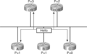
![]() To elect a DR and BDR, the routers view the OSPF priority value of the other routers during the hello packet exchange process and then use the following conditions to determine which router to select:
To elect a DR and BDR, the routers view the OSPF priority value of the other routers during the hello packet exchange process and then use the following conditions to determine which router to select:
- The router with the highest priority value is the DR, as shown in Figure 3-16.
- The router with the second-highest priority value is the BDR.
- The default for the interface OSPF priority is 1. In case of a tie, the router ID is used. The router with the highest router ID becomes the DR. The router with the second-highest router ID becomes the BDR.
- A router with a priority of 0 cannot become the DR or BDR. A router that is not the DR or BDR is a DROTHER.
- If a router with a higher priority value gets added to the network, it does not preempt the DR and BDR. The only time a DR or BDR changes is if one of them goes out of service. If the DR is out of service, the BDR becomes the DR, and a new BDR is selected. If the BDR is out of service, a new BDR is elected.
![]() The BDR does not perform any DR functions when the DR is operating. Instead, the BDR receives all the information, but the DR performs the LSA forwarding and LSDB synchronization tasks. The BDR performs the DR tasks only if the DR fails. To determine whether the DR is out of service, the BDR uses the wait timer. This timer is a reliability feature. If the BDR does not confirm that the DR is forwarding LSAs before the wait timer expires, the BDR assumes that the DR is out of service.
The BDR does not perform any DR functions when the DR is operating. Instead, the BDR receives all the information, but the DR performs the LSA forwarding and LSDB synchronization tasks. The BDR performs the DR tasks only if the DR fails. To determine whether the DR is out of service, the BDR uses the wait timer. This timer is a reliability feature. If the BDR does not confirm that the DR is forwarding LSAs before the wait timer expires, the BDR assumes that the DR is out of service.
![]() It is important to remember that the DR concept is at the link level. In a multiaccess broadcast environment each network segment has its own DR and BDR. For example, a router connected to multiple multiaccess broadcast networks can be a DR on one segment and a regular (DROTHER) router on another segment.
It is important to remember that the DR concept is at the link level. In a multiaccess broadcast environment each network segment has its own DR and BDR. For example, a router connected to multiple multiaccess broadcast networks can be a DR on one segment and a regular (DROTHER) router on another segment.
![]() Use the ip ospf priority number interface configuration command to affect which router interfaces on a multiaccess link are the DR and the BDR. The default priority is 1, and the range is from 0 to 255. The highest priority interface becomes the DR, and the second-highest priority interface becomes the BDR. Any interfaces set to 0 priority cannot be involved in the DR or BDR election process.
Use the ip ospf priority number interface configuration command to affect which router interfaces on a multiaccess link are the DR and the BDR. The default priority is 1, and the range is from 0 to 255. The highest priority interface becomes the DR, and the second-highest priority interface becomes the BDR. Any interfaces set to 0 priority cannot be involved in the DR or BDR election process.
![]() Example 3-11 illustrates an example of configuring the Fast Ethernet interface on a router with an OSPF priority of 10.
Example 3-11 illustrates an example of configuring the Fast Ethernet interface on a router with an OSPF priority of 10.
Router(config-if)#ip ospf priority 10
| Note |
|
Adjacency Behavior for a Point-to-Point Link
![]() A point-to-point network joins a single pair of routers. A T1 serial line configured with a link-layer protocol such as PPP or HDLC is an example of a point-to-point network.
A point-to-point network joins a single pair of routers. A T1 serial line configured with a link-layer protocol such as PPP or HDLC is an example of a point-to-point network.
![]() On point-to-point networks, the router dynamically detects its neighboring routers by multicasting its hello packets to all OSPF routers using the address 224.0.0.5. On point-to-point networks, neighboring routers become adjacent whenever they can communicate directly. No DR or BDR election is performed, because a point-to-point link can have only two routers, so there is no need for a DR or BDR.
On point-to-point networks, the router dynamically detects its neighboring routers by multicasting its hello packets to all OSPF routers using the address 224.0.0.5. On point-to-point networks, neighboring routers become adjacent whenever they can communicate directly. No DR or BDR election is performed, because a point-to-point link can have only two routers, so there is no need for a DR or BDR.
![]() Usually, the IP source address of an OSPF packet is set to the address of the outgoing interface on the router. If an unnumbered interface is used, the IP source address is set to the IP address of another interface on the router.
Usually, the IP source address of an OSPF packet is set to the address of the outgoing interface on the router. If an unnumbered interface is used, the IP source address is set to the IP address of another interface on the router.
![]() The default OSPF hello and dead intervals on point-to-point links are 10 seconds and 40 seconds, respectively. (The hello and dead timers can be changed with the ip ospf hello-interval seconds and ip ospf dead-interval seconds interface configuration commands.)
The default OSPF hello and dead intervals on point-to-point links are 10 seconds and 40 seconds, respectively. (The hello and dead timers can be changed with the ip ospf hello-interval seconds and ip ospf dead-interval seconds interface configuration commands.)
Adjacency Behavior for a Broadcast Network
![]() An OSPF router on a multiaccess broadcast network such as Ethernet forms an adjacency with its DR and BDR. Adjacent routers have synchronized LSDBs. A common media segment is the basis for adjacency, such as two routers connected on the same Ethernet segment. When routers first come up on the segment, they perform the hello process and then elect the DR and BDR to represent the multiaccess broadcast network. The routers then attempt to form adjacencies with the DR and BDR.
An OSPF router on a multiaccess broadcast network such as Ethernet forms an adjacency with its DR and BDR. Adjacent routers have synchronized LSDBs. A common media segment is the basis for adjacency, such as two routers connected on the same Ethernet segment. When routers first come up on the segment, they perform the hello process and then elect the DR and BDR to represent the multiaccess broadcast network. The routers then attempt to form adjacencies with the DR and BDR.
![]() The DR and BDR add value to the network in the following ways:
The DR and BDR add value to the network in the following ways:
- Reducing routing update traffic— The DR and BDR act as a central point of contact for link-state information exchange on a given multiaccess broadcast network. Therefore, each router must establish a full adjacency with the DR and the BDR only. Instead of each router exchanging link-state information with every other router on the segment, each router sends the link-state information to the DR and BDR only. The DR represents the multiaccess broadcast network in the sense that it sends link-state information from each router to all other routers in the network. This flooding process significantly reduces the router-related traffic on a segment.
- Managing link-state synchronization— The DR and BDR ensure that the other routers on the network have the same link-state information about the internetwork. In this way, the DR and BDR reduce the number of routing errors.
![]() Remember that after a DR and BDR have been selected, any router added to the broadcast network establishes full adjacencies with the DR and BDR only.
Remember that after a DR and BDR have been selected, any router added to the broadcast network establishes full adjacencies with the DR and BDR only.
Adjacency Behavior over a Layer 2 MPLS VPN
![]() As described in Chapter 2, “Configuring the Enhanced Interior Gateway Routing Protocol,” Ethernet over MPLS (EoMPLS) is used to deploy Layer 2 MPLS VPNs, in which an MPLS backbone provides a Layer 2 Ethernet port-to-port connection, as illustrated in Figure 3-17. (EoMPLS is also known as a type of Metro Ethernet service.)
As described in Chapter 2, “Configuring the Enhanced Interior Gateway Routing Protocol,” Ethernet over MPLS (EoMPLS) is used to deploy Layer 2 MPLS VPNs, in which an MPLS backbone provides a Layer 2 Ethernet port-to-port connection, as illustrated in Figure 3-17. (EoMPLS is also known as a type of Metro Ethernet service.)


![]() In Figure 3-17, Routers R1 and R2 are exchanging Ethernet frames transparently across the MPLS backbone. They are connected to provider edge (PE) routers. The PE1 router takes the Ethernet frame received from the directly connected router R1, encapsulates it into an MPLS packet and forwards it across the backbone to the PE2 router. The PE2 router decapsulates the MPLS packet and reproduces the Ethernet frame on its Ethernet link to router R2.
In Figure 3-17, Routers R1 and R2 are exchanging Ethernet frames transparently across the MPLS backbone. They are connected to provider edge (PE) routers. The PE1 router takes the Ethernet frame received from the directly connected router R1, encapsulates it into an MPLS packet and forwards it across the backbone to the PE2 router. The PE2 router decapsulates the MPLS packet and reproduces the Ethernet frame on its Ethernet link to router R2.
![]() EoMPLS does not include any MAC layer address learning and filtering. Therefore routers PE1 and PE2 do not filter any frames based on MAC addresses. EoMPLS also does not use the Spanning Tree Protocol (STP). Bridge protocol data units (BPDUs) are propagated transparently and not processed, so LAN loop detection must be performed by other devices or avoided by design. A service provider can use LAN switches in conjunction with EoMPLS to provide these features.
EoMPLS does not include any MAC layer address learning and filtering. Therefore routers PE1 and PE2 do not filter any frames based on MAC addresses. EoMPLS also does not use the Spanning Tree Protocol (STP). Bridge protocol data units (BPDUs) are propagated transparently and not processed, so LAN loop detection must be performed by other devices or avoided by design. A service provider can use LAN switches in conjunction with EoMPLS to provide these features.
![]() The two customer routers R1 and R2 in Figure 3-17 could also be connected to the MPLS edge routers PE1 and PE2 via virtual LAN (VLAN) subinterfaces, using different subinterfaces in the PE1 and PE2 routers to connect to different VLANs. In this case, the PE1 subinterface to the VLAN where the router R1 is connected is used for EoMPLS forwarding. The Ethernet frame that arrives from router R1 on the specific VLAN subinterface is encapsulated into MPLS and forwarded across the backbone to router PE2. The PE2 router decapsulates the packet and reproduces the Ethernet frame on its outgoing VLAN subinterface to router R2.
The two customer routers R1 and R2 in Figure 3-17 could also be connected to the MPLS edge routers PE1 and PE2 via virtual LAN (VLAN) subinterfaces, using different subinterfaces in the PE1 and PE2 routers to connect to different VLANs. In this case, the PE1 subinterface to the VLAN where the router R1 is connected is used for EoMPLS forwarding. The Ethernet frame that arrives from router R1 on the specific VLAN subinterface is encapsulated into MPLS and forwarded across the backbone to router PE2. The PE2 router decapsulates the packet and reproduces the Ethernet frame on its outgoing VLAN subinterface to router R2.
![]() When you are deploying OSPF over EoMPLS, there are no changes to the OSPF configuration from the customer perspective. For example, the OSPF process needs to be enabled, and network commands must be configured to include all the interfaces that will run in the OSPF process, in the appropriate OSPF areas. These interfaces include the link toward the PE routers (Routers PE1 and PE2) over which the Routers R1 and R2 will form their neighbor relationship.
When you are deploying OSPF over EoMPLS, there are no changes to the OSPF configuration from the customer perspective. For example, the OSPF process needs to be enabled, and network commands must be configured to include all the interfaces that will run in the OSPF process, in the appropriate OSPF areas. These interfaces include the link toward the PE routers (Routers PE1 and PE2) over which the Routers R1 and R2 will form their neighbor relationship.
![]() From the OSPF perspective, the Layer 2 MPLS VPN backbone and the PE1 and PE2 routers are not visible. A neighbor relationship is established directly between Routers R1 and R2 over the MPLS backbone, and behaves in the same way as on an Ethernet broadcast network. The OSPF network type is a multiaccess broadcast network, so DR and BDR routers are elected. Other routers form full adjacencies only with the DR and BDR.
From the OSPF perspective, the Layer 2 MPLS VPN backbone and the PE1 and PE2 routers are not visible. A neighbor relationship is established directly between Routers R1 and R2 over the MPLS backbone, and behaves in the same way as on an Ethernet broadcast network. The OSPF network type is a multiaccess broadcast network, so DR and BDR routers are elected. Other routers form full adjacencies only with the DR and BDR.
Adjacency Behavior over a Layer 3 MPLS VPN
![]() As described in Chapter 2, a Layer 3 MPLS VPN architecture provides a peer-to-peer VPN where PE routers participate in customer routing, providing optimum routing between customer sites. Figure 3-18 illustrates such a network. The PE routers carry a separate set of routes for each customer, isolating customers from each other. In Layer 3 MPLS VPN technology (even when running OSPF as a PE-CE routing protocol), the following requirements must be met:
As described in Chapter 2, a Layer 3 MPLS VPN architecture provides a peer-to-peer VPN where PE routers participate in customer routing, providing optimum routing between customer sites. Figure 3-18 illustrates such a network. The PE routers carry a separate set of routes for each customer, isolating customers from each other. In Layer 3 MPLS VPN technology (even when running OSPF as a PE-CE routing protocol), the following requirements must be met:
- The customer routers (also called the C-routers, R1 and R2 in the figure) should not be MPLS VPN-aware. They should run standard IP routing software.
- The provider core routers (also called the P-routers, within the cloud in the figure) must not carry customer (VPN) routes, to make the MPLS VPN solution scalable.
- The provider edge routers (the PE routers) must support MPLS VPN services and traditional IP services.


![]() To the customer routers running OSPF (Routers R1 and R2 in Figure 3-18), the Layer 3 MPLS VPN backbone looks like a standard corporate backbone. The customer routers run standard IP routing software and exchange routing updates with the PE routers that appear to them as normal routers in the customer’s network.
To the customer routers running OSPF (Routers R1 and R2 in Figure 3-18), the Layer 3 MPLS VPN backbone looks like a standard corporate backbone. The customer routers run standard IP routing software and exchange routing updates with the PE routers that appear to them as normal routers in the customer’s network.
![]() OSPF is enabled on these routers on proper interfaces using the network command. The customer has to agree upon OSPF parameters (such as authentication) with the service provider (SP) to ensure connectivity. These parameters are often governed by the SP.
OSPF is enabled on these routers on proper interfaces using the network command. The customer has to agree upon OSPF parameters (such as authentication) with the service provider (SP) to ensure connectivity. These parameters are often governed by the SP.
![]() The P-routers are hidden from the customer’s routers, and the customer edge (CE) routers are unaware of MPLS VPN. The internal topology of the Layer 3 MPLS backbone is therefore totally transparent to the customer. The PE routers receive IPv4 routing updates from the CE routers and install the updates in the appropriate VRF table. This part of the configuration and operation is the SP’s responsibility.
The P-routers are hidden from the customer’s routers, and the customer edge (CE) routers are unaware of MPLS VPN. The internal topology of the Layer 3 MPLS backbone is therefore totally transparent to the customer. The PE routers receive IPv4 routing updates from the CE routers and install the updates in the appropriate VRF table. This part of the configuration and operation is the SP’s responsibility.
![]() The OSPF network type of the CE-PE link can be point to point, broadcast or NBMA.
The OSPF network type of the CE-PE link can be point to point, broadcast or NBMA.
Adjacency Behavior for an NBMA Network
![]() When a single interface interconnects multiple sites over an NBMA network, the network’s nonbroadcast nature can create reachability issues. NBMA networks can support more than two routers, but they have no inherent broadcast capability. To implement broadcasting or multicasting, the router replicates the packets to be broadcast or multicast and sends them individually on each permanent virtual circuit (PVC) to all destinations. This process is CPU and bandwidth intensive. If the NBMA topology is not fully meshed, a broadcast or multicast sent by one router does not reach all the other routers. Frame Relay, ATM, and X.25 are examples of NBMA networks.
When a single interface interconnects multiple sites over an NBMA network, the network’s nonbroadcast nature can create reachability issues. NBMA networks can support more than two routers, but they have no inherent broadcast capability. To implement broadcasting or multicasting, the router replicates the packets to be broadcast or multicast and sends them individually on each permanent virtual circuit (PVC) to all destinations. This process is CPU and bandwidth intensive. If the NBMA topology is not fully meshed, a broadcast or multicast sent by one router does not reach all the other routers. Frame Relay, ATM, and X.25 are examples of NBMA networks.
![]() The default OSPF hello and dead intervals on NBMA interfaces are 30 seconds and 120 seconds, respectively.
The default OSPF hello and dead intervals on NBMA interfaces are 30 seconds and 120 seconds, respectively.
![]() The following sections detail issues with DR elections in an NBMA topology, OSPF topology options in a Frame Relay network, OSPF modes for NBMA topologies, and how to configure OSPF in each of these modes.
The following sections detail issues with DR elections in an NBMA topology, OSPF topology options in a Frame Relay network, OSPF modes for NBMA topologies, and how to configure OSPF in each of these modes.
DR Election in an NBMA Topology
![]() By default, OSPF cannot automatically build adjacencies with neighbor routers over NBMA interfaces.
By default, OSPF cannot automatically build adjacencies with neighbor routers over NBMA interfaces.
![]() OSPF considers the NBMA environment to function similarly to other multiaccess media such as Ethernet. However, NBMA networks are usually hub-and-spoke (star) topologies using PVCs or switched virtual circuits (SVCs). In these cases, the physical topology does not provide the multiaccess capability on which OSPF relies.
OSPF considers the NBMA environment to function similarly to other multiaccess media such as Ethernet. However, NBMA networks are usually hub-and-spoke (star) topologies using PVCs or switched virtual circuits (SVCs). In these cases, the physical topology does not provide the multiaccess capability on which OSPF relies.
![]() The election of the DR becomes an issue in NBMA topologies because the DR and BDR need to have full Layer 2 connectivity with all routers in the NBMA network. The DR and BDR also need to have a list of all the other routers so that they can establish adjacencies.
The election of the DR becomes an issue in NBMA topologies because the DR and BDR need to have full Layer 2 connectivity with all routers in the NBMA network. The DR and BDR also need to have a list of all the other routers so that they can establish adjacencies.
OSPF over Frame Relay Topology Options
![]() Depending on the network topology, several OSPF configuration choices are available for a Frame Relay network. By default, interfaces that support Frame Relay are multipoint connection types. With Frame Relay, remote sites interconnect in a variety of ways, as shown in Figure 3-19. The following examples are types of Frame Relay topologies:
Depending on the network topology, several OSPF configuration choices are available for a Frame Relay network. By default, interfaces that support Frame Relay are multipoint connection types. With Frame Relay, remote sites interconnect in a variety of ways, as shown in Figure 3-19. The following examples are types of Frame Relay topologies:
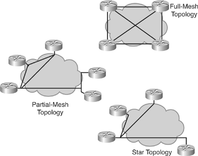
- Star topology— A star topology, also known as a hub-and-spoke configuration, is the most common Frame Relay network topology. In this topology, remote sites connect to a central site that generally provides a service or application. The star topology is the least expensive topology because it requires the fewest PVCs. The central router provides a multipoint connection because it typically uses a single interface to interconnect multiple PVCs.
- Full-mesh topology— In a full-mesh topology, all routers have virtual circuits (VCs) to all other destinations. This method, although costly, provides direct connections from each site to all other sites and allows for redundancy. As the number of nodes in the full-mesh topology increases, the topology becomes increasingly expensive. To calculate how many VCs are needed to implement a full-mesh topology, use the formula n(n − 1)/2, where n is the number of nodes in the network.
- Partial-mesh topology— In a partial-mesh topology, not all sites have direct access to a central site. This method reduces the cost compared to implementing a full-mesh topology.
OSPF over NBMA Topology Modes of Operation
![]() OSPF on Cisco routers can operate in various modes over NBMA networks. The choice of modes available depends on the topology of the NBMA network. Each mode has unique configuration requirements.
OSPF on Cisco routers can operate in various modes over NBMA networks. The choice of modes available depends on the topology of the NBMA network. Each mode has unique configuration requirements.
![]() As described in RFC 2328, the following are the two official modes for OSPF in NBMA topologies:
As described in RFC 2328, the following are the two official modes for OSPF in NBMA topologies:
- Nonbroadcast— The nonbroadcast (NBMA) mode simulates the operation of OSPF in broadcast networks. Neighbors must be configured manually, and DR and BDR election is required. This configuration is typically used with full-mesh networks.
- Point-to-multipoint— Point-to-multipoint mode treats the nonbroadcast network as a collection of point-to-point links. In this environment, the routers automatically identify their neighboring routers but do not elect a DR and BDR. This configuration is typically used with partial-mesh networks.
![]() The choice between nonbroadcast and point-to-multipoint modes determines how the Hello protocol and flooding work over the nonbroadcast network.
The choice between nonbroadcast and point-to-multipoint modes determines how the Hello protocol and flooding work over the nonbroadcast network.
![]() The main advantage of point-to-multipoint mode is that it requires less manual configuration. The main advantage of nonbroadcast mode is that there is less overhead traffic compared to point-to-multipoint mode.
The main advantage of point-to-multipoint mode is that it requires less manual configuration. The main advantage of nonbroadcast mode is that there is less overhead traffic compared to point-to-multipoint mode.
![]() In addition, Cisco offers the following modes for OSPF operation in an NBMA network:
In addition, Cisco offers the following modes for OSPF operation in an NBMA network:
- Point-to-multipoint nonbroadcast
- Broadcast
- Point-to-point
Selecting the OSPF Network Type for NBMA Networks
![]() Use the ip ospf network {broadcast | non-broadcast | point-to-multipoint [non-broadcast] | point-to-point} interface configuration command to select the OSPF mode. Table 3-8 describes the parameters of this command, and the modes, in greater detail.
Use the ip ospf network {broadcast | non-broadcast | point-to-multipoint [non-broadcast] | point-to-point} interface configuration command to select the OSPF mode. Table 3-8 describes the parameters of this command, and the modes, in greater detail.
|
| |
|---|---|
|
|
|
|
|
|
|
|
|
|
|
|
|
|
|
![]() The default OSPF modes are as follows:
The default OSPF modes are as follows:
- The default OSPF mode on a point-to-point Frame Relay subinterface is the point-to-point mode.
- The default OSPF mode on a Frame Relay multipoint subinterface is the nonbroadcast mode.
- The default OSPF mode on a main Frame Relay interface is also the nonbroadcast mode.
![]() The following sections detail the configuration of OSPF in each of these modes.
The following sections detail the configuration of OSPF in each of these modes.
OSPF Configuration in Cisco Broadcast Mode
![]() Broadcast mode is a workaround for statically listing all existing neighboring routers. The interface is set to broadcast and behaves as though the router connects to a LAN. DR and BDR election is still performed. Therefore, take special care to ensure either a full-mesh topology or a static election of the DR based on the interface priority to ensure that the selected DR and BDR have full connectivity to all other neighbor routers.
Broadcast mode is a workaround for statically listing all existing neighboring routers. The interface is set to broadcast and behaves as though the router connects to a LAN. DR and BDR election is still performed. Therefore, take special care to ensure either a full-mesh topology or a static election of the DR based on the interface priority to ensure that the selected DR and BDR have full connectivity to all other neighbor routers.
![]() Example 3-12 shows a sample configuration of a Frame Relay router in a full-mesh topology, with the broadcast mode of operation defined.
Example 3-12 shows a sample configuration of a Frame Relay router in a full-mesh topology, with the broadcast mode of operation defined.
Router(config-if)#encapsulation frame-relay
Router(config-if)#ip ospf network broadcast
OSPF Nonbroadcast Mode Configuration
![]() In nonbroadcast mode, OSPF emulates operation over a broadcast network. A DR and BDR are elected for the NBMA network, and the DR originates an LSA for the network. In this environment, the routers are usually fully meshed to facilitate the establishment of adjacencies among them. If the routers are not fully meshed, the DR and BDR should be selected manually to ensure that the selected DR and BDR have full connectivity to all other neighbor routers. Neighboring routers are statically defined to start the DR/BDR election process. When using nonbroadcast mode, all routers are on one IP subnet.
In nonbroadcast mode, OSPF emulates operation over a broadcast network. A DR and BDR are elected for the NBMA network, and the DR originates an LSA for the network. In this environment, the routers are usually fully meshed to facilitate the establishment of adjacencies among them. If the routers are not fully meshed, the DR and BDR should be selected manually to ensure that the selected DR and BDR have full connectivity to all other neighbor routers. Neighboring routers are statically defined to start the DR/BDR election process. When using nonbroadcast mode, all routers are on one IP subnet.
![]() For flooding over a nonbroadcast interface, the LSU packet must be replicated for each PVC. The updates are sent to each of the interface’s neighboring routers, as defined in the neighbor table.
For flooding over a nonbroadcast interface, the LSU packet must be replicated for each PVC. The updates are sent to each of the interface’s neighboring routers, as defined in the neighbor table.
![]() When few neighbors exist in the network, nonbroadcast mode is the most efficient way to run OSPF over NBMA networks because it has less overhead than point-to-multipoint mode.
When few neighbors exist in the network, nonbroadcast mode is the most efficient way to run OSPF over NBMA networks because it has less overhead than point-to-multipoint mode.
![]() After you enable the OSPF process for specific interfaces, you configure nonbroadcast mode by
After you enable the OSPF process for specific interfaces, you configure nonbroadcast mode by
- Manually configuring OSPF neighbors
- Defining the OSPF network type as nonbroadcast (unless it is the default)
![]() Use the neighbor ip-address [priority number] [poll-interval number] [cost number] [database-filter all] router configuration command to statically define adjacent relationships in NBMA networks using the nonbroadcast mode. Table 3-9 describes the parameters of this command in detail.
Use the neighbor ip-address [priority number] [poll-interval number] [cost number] [database-filter all] router configuration command to statically define adjacent relationships in NBMA networks using the nonbroadcast mode. Table 3-9 describes the parameters of this command in detail.
|
|
|
|---|---|
|
|
|
|
|
|
|
|
|
|
|
|
|
|
|
| Note |
|
![]() Figure 3-20 shows an example of statically defining adjacencies. All three routers are using the default nonbroadcast mode on their Frame Relay interfaces, so neighboring routers must be manually configured on each. The priority parameter is set to 0 for Routers B and C to ensure that Router A becomes the DR. Only Router A has full connectivity to the other two routers because the topology is not a full-mesh. No BDR will be elected in this case.
Figure 3-20 shows an example of statically defining adjacencies. All three routers are using the default nonbroadcast mode on their Frame Relay interfaces, so neighboring routers must be manually configured on each. The priority parameter is set to 0 for Routers B and C to ensure that Router A becomes the DR. Only Router A has full connectivity to the other two routers because the topology is not a full-mesh. No BDR will be elected in this case.


![]() In nonbroadcast mode, neighbor statements are required only on the DR and BDR. In a hub-and-spoke topology, neighbor statements must be placed on the hub, which must be configured to become the DR by being assigned a higher priority. Neighbor statements are not mandatory on the spoke routers. In a full-mesh NBMA topology, you might need neighbor statements on all routers unless the DR and BDR are statically configured using the ip ospf priority command.
In nonbroadcast mode, neighbor statements are required only on the DR and BDR. In a hub-and-spoke topology, neighbor statements must be placed on the hub, which must be configured to become the DR by being assigned a higher priority. Neighbor statements are not mandatory on the spoke routers. In a full-mesh NBMA topology, you might need neighbor statements on all routers unless the DR and BDR are statically configured using the ip ospf priority command.
![]() The show ip ospf neighbor command displays OSPF neighbor information on a per-interface basis, as described earlier in the “Verifying OSPF Operations” section. Example 3-13 demonstrates sample output from the show ip ospf neighbor command for Router A in Figure 3-20 (with the OSPF priorities of Routers B and C set to 0 at the interface level, as noted). Router A has a serial Frame Relay interface and a Fast Ethernet interface. The Serial 0/0/0 interface on this router has two neighbors; both have a state of FULL/DROTHER. DROTHER means that the neighboring router is not a DR or BDR (because Router A is the DR and there is no BDR in this network). The neighbor learned on Fast Ethernet 0/0 has a state of FULL/BDR, which means that it has successfully exchanged LSDB information with the router issuing the show command, and that it is the BDR.
The show ip ospf neighbor command displays OSPF neighbor information on a per-interface basis, as described earlier in the “Verifying OSPF Operations” section. Example 3-13 demonstrates sample output from the show ip ospf neighbor command for Router A in Figure 3-20 (with the OSPF priorities of Routers B and C set to 0 at the interface level, as noted). Router A has a serial Frame Relay interface and a Fast Ethernet interface. The Serial 0/0/0 interface on this router has two neighbors; both have a state of FULL/DROTHER. DROTHER means that the neighboring router is not a DR or BDR (because Router A is the DR and there is no BDR in this network). The neighbor learned on Fast Ethernet 0/0 has a state of FULL/BDR, which means that it has successfully exchanged LSDB information with the router issuing the show command, and that it is the BDR.
Neighbor ID Pri State Dead Time Address Interface
192.168.1.3 0 FULL/DROTHER 00:01:57 192.168.1.3 Serial0/0/0
192.168.1.2 0 FULL/DROTHER 00:01:33 192.168.1.2 Serial0/0/0
172.16.1.1 1 FULL/BDR 00:00:34 172.16.1.1 FastEthernet0/0
OSPF Configuration in Point-to-Multipoint Mode
![]() Networks in RFC 2328-compliant point-to-multipoint mode are designed to work with partial-mesh or star topologies. In point-to-multipoint mode, OSPF treats all router-to-router connections over the nonbroadcast network as if they are point-to-point links.
Networks in RFC 2328-compliant point-to-multipoint mode are designed to work with partial-mesh or star topologies. In point-to-multipoint mode, OSPF treats all router-to-router connections over the nonbroadcast network as if they are point-to-point links.
![]() In point-to-multipoint mode, DRs are not used, and a type 2 network LSA is not flooded to adjacent routers. (The “Understanding OSPF LSAs” section, later in this chapter, covers the different types of LSAs in greater detail.) Instead, OSPF point-to-multipoint works by exchanging additional LSUs that are designed to automatically discover neighboring routers and add them to the neighbor table.
In point-to-multipoint mode, DRs are not used, and a type 2 network LSA is not flooded to adjacent routers. (The “Understanding OSPF LSAs” section, later in this chapter, covers the different types of LSAs in greater detail.) Instead, OSPF point-to-multipoint works by exchanging additional LSUs that are designed to automatically discover neighboring routers and add them to the neighbor table.
![]() In large networks, using point-to-multipoint mode reduces the number of PVCs required for complete connectivity, because you are not required to have a full-mesh topology. In addition, not having a full-mesh topology reduces the number of neighbor entries in the neighborship table.
In large networks, using point-to-multipoint mode reduces the number of PVCs required for complete connectivity, because you are not required to have a full-mesh topology. In addition, not having a full-mesh topology reduces the number of neighbor entries in the neighborship table.
![]() Point-to-multipoint mode has the following properties:
Point-to-multipoint mode has the following properties:
- Does not require a full-mesh network— This environment allows routing to occur between two routers that are not directly connected but that are connected through a router that has VCs to each of the two routers. All three routers connected to the Frame Relay network in Figure 3-21 could be configured for point-to-multipoint mode.
- Does not require a static neighbor configuration— In nonbroadcast mode, neighboring routers are statically defined to start the DR election process, and allow the exchange of routing updates. However, because point-to-multipoint mode treats the network as a collection of point-to-point links, multicast hello packets discover neighboring routers dynamically. Statically configuring neighboring routers is not necessary.
- Uses one IP subnet— As in nonbroadcast mode, when using point-to-multipoint mode, all routers are on one IP subnet.
- Duplicates LSA packets— Also as in nonbroadcast mode, when flooding out a nonbroadcast interface in point-to-multipoint mode, the router must replicate the LSU. The LSU packet is sent to each of the interface’s neighboring routers, as defined in the neighbor table.

![]() Example 3-14 shows partial configurations of routers A and C in Figure 3-21 in point-to-multipoint mode. This configuration does not require subinterfaces and uses only a single subnet. In point-to-multipoint mode, a DR or BDR is not required, so DR and BDR election and priorities are not a concern.
Example 3-14 shows partial configurations of routers A and C in Figure 3-21 in point-to-multipoint mode. This configuration does not require subinterfaces and uses only a single subnet. In point-to-multipoint mode, a DR or BDR is not required, so DR and BDR election and priorities are not a concern.
RouterA(config-if)#ip address 192.168.1.1 255.255.255.0
RouterA(config-if)#encapsulation frame-relay
RouterA(config-if)#ip ospf network point-to-multipoint
![]() Example 3-15 demonstrates output from the show ip ospf interface command, which displays key OSPF details for each interface. This sample output is from Router A in Figure 3-21.
Example 3-15 demonstrates output from the show ip ospf interface command, which displays key OSPF details for each interface. This sample output is from Router A in Figure 3-21.
Serial0/0/0 is up, line protocol is up
Internet Address 192.168.1.1/24, Area 0
Process ID 100, Router ID 192.168.1.1, Network Type POINT_TO_MULTIPOINT, Cost:
781
Transmit Delay is 1 sec, State POINT_TO_MULTIPOINT
Timer intervals configured, Hello 30, Dead 120, Wait 120, Retransmit 5
oob-resync timeout 120
Hello due in 00:00:26
Supports Link-local Signaling (LLS)
Index 2/2, flood queue length 0
Next 0x0(0)/0x0(0)
Last flood scan length is 1, maximum is 1
Last flood scan time is 0 msec, maximum is 4 msec
Neighbor Count is 2, Adjacent neighbor count is 2
Adjacent with neighbor 192.168.1.3
Adjacent with neighbor 192.168.1.2
Suppress hello for 0 neighbor(s)
RouterA#
![]() The OSPF network type, area number, cost, and state of the interface are all displayed. The hello interval for a point-to-multipoint interface is 30 seconds and the dead interval is 120 seconds. Point-to-multipoint mode, point-to-multipoint nonbroadcast mode, and nonbroadcast mode default to a 30-second hello timer, while point-to-point mode and broadcast mode default to a 10-second hello timer. Recall that the hello and dead timers on the neighboring interfaces must match for the neighbors to form successful adjacencies.
The OSPF network type, area number, cost, and state of the interface are all displayed. The hello interval for a point-to-multipoint interface is 30 seconds and the dead interval is 120 seconds. Point-to-multipoint mode, point-to-multipoint nonbroadcast mode, and nonbroadcast mode default to a 30-second hello timer, while point-to-point mode and broadcast mode default to a 10-second hello timer. Recall that the hello and dead timers on the neighboring interfaces must match for the neighbors to form successful adjacencies.
![]() The listed adjacent neighboring routers are all dynamically learned.
The listed adjacent neighboring routers are all dynamically learned.
OSPF Configuration in Cisco Point-to-Multipoint Nonbroadcast Mode
![]() Point-to-multipoint nonbroadcast mode is a Cisco extension of the RFC-compliant point-to-multipoint mode. You must statically define neighbors, and you can modify the cost of the link to the neighboring router to reflect the different bandwidths of each link. The RFC point-to-multipoint mode was developed to support underlying point-to-multipoint VCs that support multicast and broadcast. If multicast and broadcast are not enabled on the VCs, RFC-compliant point-to-multipoint mode cannot be used because the router cannot dynamically discover its neighboring routers using the hello multicast packets. In this case, the Cisco point-to-multipoint nonbroadcast mode should be used instead.
Point-to-multipoint nonbroadcast mode is a Cisco extension of the RFC-compliant point-to-multipoint mode. You must statically define neighbors, and you can modify the cost of the link to the neighboring router to reflect the different bandwidths of each link. The RFC point-to-multipoint mode was developed to support underlying point-to-multipoint VCs that support multicast and broadcast. If multicast and broadcast are not enabled on the VCs, RFC-compliant point-to-multipoint mode cannot be used because the router cannot dynamically discover its neighboring routers using the hello multicast packets. In this case, the Cisco point-to-multipoint nonbroadcast mode should be used instead.
![]() In point-to-multipoint nonbroadcast mode, you must statically define neighbors, like in nonbroadcast mode. As in point-to-multipoint mode, DRs and BDRs are not elected.
In point-to-multipoint nonbroadcast mode, you must statically define neighbors, like in nonbroadcast mode. As in point-to-multipoint mode, DRs and BDRs are not elected.
Using Subinterfaces in OSPF over Frame Relay Configuration
![]() OSPF can also be run over subinterfaces. This section first describes subinterfaces and how to configure them, and then describes OSPF operation over subinterfaces.
OSPF can also be run over subinterfaces. This section first describes subinterfaces and how to configure them, and then describes OSPF operation over subinterfaces.
![]() A physical interface can be split into multiple logical interfaces called subinterfaces. Subinterfaces were originally created to better handle issues caused by split horizon over NBMA for distance vector-based routing protocols. Each subinterface requires an IP subnet.
A physical interface can be split into multiple logical interfaces called subinterfaces. Subinterfaces were originally created to better handle issues caused by split horizon over NBMA for distance vector-based routing protocols. Each subinterface requires an IP subnet.
![]() Each subinterface is defined as either a point-to-point or multipoint interface. A point-to-point subinterface has similar properties to a physical point-to-point interface.
Each subinterface is defined as either a point-to-point or multipoint interface. A point-to-point subinterface has similar properties to a physical point-to-point interface.
![]() Define subinterfaces using the interface serial number.subinterface-number {multipoint | point-to-point} global configuration command. Table 3-10 lists the parameters of this command.
Define subinterfaces using the interface serial number.subinterface-number {multipoint | point-to-point} global configuration command. Table 3-10 lists the parameters of this command.
|
|
|
|---|---|
|
|
|
|
|
|
|
|
|
![]() The choice of point-to-point or multipoint keywords affects the OSPF operation, as described in the sections that follow.
The choice of point-to-point or multipoint keywords affects the OSPF operation, as described in the sections that follow.
![]() It is important to remember that OSPF defaults to point-to-point mode on point-to-point subinterfaces, and to nonbroadcast mode on the multipoint subinterfaces.
It is important to remember that OSPF defaults to point-to-point mode on point-to-point subinterfaces, and to nonbroadcast mode on the multipoint subinterfaces.
OSPF over Point-to-Point Subinterfaces
![]() When point-to-point subinterfaces are configured, each virtual circuit (PVC and SVC) gets its own subinterface. A point-to-point subinterface has the properties of any physical point-to-point interface: there is no DR or BDR and neighbor discovery is automatic, so neighbors do not need to be configured.
When point-to-point subinterfaces are configured, each virtual circuit (PVC and SVC) gets its own subinterface. A point-to-point subinterface has the properties of any physical point-to-point interface: there is no DR or BDR and neighbor discovery is automatic, so neighbors do not need to be configured.
![]() Point-to-point mode is used when only two nodes exist on the NBMA network. This mode is typically used only with point-to-point subinterfaces. Each point-to-point connection is one IP subnet. An adjacency forms over the point-to-point network with no DR or BDR election.
Point-to-point mode is used when only two nodes exist on the NBMA network. This mode is typically used only with point-to-point subinterfaces. Each point-to-point connection is one IP subnet. An adjacency forms over the point-to-point network with no DR or BDR election.
![]() In the example in Figure 3-22 and the configurations in Example 3-16, Router A’s serial 0/0/0 interface is configured with point-to-point subinterfaces. Although all three routers on the Frame Relay network have only one physical serial port, Router A appears to have two logical ports. Each logical port (subinterface) has its own IP address and operates in OSPF point-to-point mode. Each subinterface is on its own IP subnet. Router B’s configuration is also presented in Example 3-16.
In the example in Figure 3-22 and the configurations in Example 3-16, Router A’s serial 0/0/0 interface is configured with point-to-point subinterfaces. Although all three routers on the Frame Relay network have only one physical serial port, Router A appears to have two logical ports. Each logical port (subinterface) has its own IP address and operates in OSPF point-to-point mode. Each subinterface is on its own IP subnet. Router B’s configuration is also presented in Example 3-16.
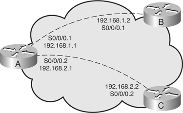
interface Serial0/0/0
no ip address
encapsulation frame-relay
!
interface Serial0/0/0.1 point-to-point
ip address 192.168.1.1 255.255.255.0
frame-relay interface-dlci 121
interface Serial0/0/0.2 point-to-point
ip address 192.168.2.1 255.255.255.0
frame-relay interface-dlci 132
RouterB#
interface Serial0/0/0
no ip address
encapsulation frame-relay
!
interface Serial0/0/0.1 point-to-point
ip address 192.168.1.2 255.255.255.0
frame-relay interface-dlci 122
OSPF over Multipoint Subinterfaces
![]() When multipoint subinterfaces are configured, multiple virtual circuits (PVCs or SVCs) exist on a single subinterface. Multipoint Frame Relay subinterfaces default to OSPF nonbroadcast mode, which requires neighbors to be statically configured and a DR and BDR election.
When multipoint subinterfaces are configured, multiple virtual circuits (PVCs or SVCs) exist on a single subinterface. Multipoint Frame Relay subinterfaces default to OSPF nonbroadcast mode, which requires neighbors to be statically configured and a DR and BDR election.
![]() In the example in Figure 3-23 and partial configuration in Example 3-17, Router A has one point-to-point subinterface and one multipoint subinterface. The multipoint subinterface supports two other routers in a single subnet. The configuration for Routers B and C are also presented in Example 3-17. Router D’s configuration is similar to Router C’s configuration.
In the example in Figure 3-23 and partial configuration in Example 3-17, Router A has one point-to-point subinterface and one multipoint subinterface. The multipoint subinterface supports two other routers in a single subnet. The configuration for Routers B and C are also presented in Example 3-17. Router D’s configuration is similar to Router C’s configuration.


interface Serial0/0/0.1 point-to-point
ip address 192.168.1.1 255.255.255.0
OSPF Configuration in Cisco Point-to-Point Mode
![]() Although the Cisco point-to-point mode is typically used only with point-to-point subinterfaces, it can also be used when a single PVC exists on a serial interface and point-to-point behavior is desired. In this mode, the PVC emulates a leased line. Because they are treated as point-to-point links, DR and BDR are not used, and only a single subnet is used on each point-to-point link.
Although the Cisco point-to-point mode is typically used only with point-to-point subinterfaces, it can also be used when a single PVC exists on a serial interface and point-to-point behavior is desired. In this mode, the PVC emulates a leased line. Because they are treated as point-to-point links, DR and BDR are not used, and only a single subnet is used on each point-to-point link.
| Note |
|
![]() Figure 3-24 and the partial configurations of routers A and B in Example 3-18 illustrate the use of point-to-point mode. Subinterfaces are not used, and only a single subnet is used. Because the default OSPF mode on a Frame Relay main interface is nonbroadcast mode, it is necessary to configure the ip ospf network point-to-point command.
Figure 3-24 and the partial configurations of routers A and B in Example 3-18 illustrate the use of point-to-point mode. Subinterfaces are not used, and only a single subnet is used. Because the default OSPF mode on a Frame Relay main interface is nonbroadcast mode, it is necessary to configure the ip ospf network point-to-point command.


interface Serial0/0/0
ip address 192.168.1.1 255.255.255.0
encapsulation frame-relay
ip ospf network point-to-point
OSPF over NBMA Modes of Operation Summary
![]() Table 3-11 briefly compares the different modes of operation for OSPF.
Table 3-11 briefly compares the different modes of operation for OSPF.
|
|
|
|
|
|
| |
|---|---|---|---|---|---|---|
|
|
|
|
|
|
|
|
|
|
|
|
|
|
|
|
|
|
|
|
|
|
|
|
|
|
|
|
|
|
|
|
|
|
|
|
|
|
|
|
Displaying OSPF Adjacency Activity
![]() Use the debug ip ospf adj command to track OSPF adjacencies as they go up or down. Debugging enables you to see exactly which OSPF packets are being sent between routers. The ability to see packets as they are sent over a link is an invaluable tool to the troubleshooter.
Use the debug ip ospf adj command to track OSPF adjacencies as they go up or down. Debugging enables you to see exactly which OSPF packets are being sent between routers. The ability to see packets as they are sent over a link is an invaluable tool to the troubleshooter.
| Note |
|
![]() The debug output in Example 3-19 illustrates the activity on a serial interface in point-to-point mode. No DR/BDR election occurs. However, the adjacency forms, allowing DBD packets to be sent during the exchange process. Notice that the neighbor relationship passes through the two-way phase and into the exchange phase. After database description packets are sent between routers, the neighbors move into the final state, FULL adjacency.
The debug output in Example 3-19 illustrates the activity on a serial interface in point-to-point mode. No DR/BDR election occurs. However, the adjacency forms, allowing DBD packets to be sent during the exchange process. Notice that the neighbor relationship passes through the two-way phase and into the exchange phase. After database description packets are sent between routers, the neighbors move into the final state, FULL adjacency.
OSPF: Interface Serial0/0/0.1 going Up
OSPF: Build router LSA for area 0, router ID 192.168.1.1, seq 0x80000023
OSPF: Rcv DBD from 192.168.1.2 on Serial0/0/0.1 seq 0xCF0 opt 0x52 flag 0x7 len
32 mtu 1500 state INIT
OSPF: 2 Way Communication to 192.168.1.2 on Serial0/0/0.1, state 2WAY
OSPF: Send DBD to 192.168.1.2 on Serial0/0/0.1 seq 0xF4D opt 0x52 flag 0x7 len
32
OSPF: NBR Negotiation Done. We are the SLAVE
OSPF: Send DBD to 192.168.1.2 on Serial0/0/0.1 seq 0xCF0 opt 0x52 flag 0x2 len
132
OSPF: Rcv DBD from 192.168.1.2 on Serial0/0/0.1 seq 0xCF1 opt 0x52 flag 0x3 len
132 mtu 1500 state EXCHANGE
OSPF: Send DBD to 192.168.1.2 on Serial0/0/0.1 seq 0xCF1 opt 0x52 flag 0x0 len
32
OSPF: Database request to 192.168.1.2
OSPF: sent LS REQ packet to 192.168.1.2, length 12
OSPF: Rcv DBD from 192.168.1.2 on Serial0/0/0.1 seq 0xCF2 opt 0x52 flag 0x1 len
32 mtu 1500 state EXCHANGE
OSPF: Exchange Done with 192.168.1.2 on Serial0/0/0.1
OSPF: Send DBD to 192.168.1.2 on Serial0/0/0.1 seq 0xCF2 opt 0x52 flag 0x0 len
32
OSPF: Synchronized with 192.168.1.2 on Serial0/0/0.1, state FULL
%OSPF-5-ADJCHG: Process 100, Nbr 192.168.1.2 on Serial0/0/0.1 from LOADING to
FULL, Loading Done
OSPF: Build router LSA for area 0, router ID 192.168.1.1, seq 0x80000024
![]() The debug output in Example 3-20 demonstrates the DR/BDR election process on a Fast Ethernet interface. The OSPF default behavior on a Fast Ethernet link is broadcast mode. First, the DR and BDR are selected, and then the exchange process occurs.
The debug output in Example 3-20 demonstrates the DR/BDR election process on a Fast Ethernet interface. The OSPF default behavior on a Fast Ethernet link is broadcast mode. First, the DR and BDR are selected, and then the exchange process occurs.
OSPF: Interface FastEthernet0/0 going Up
OSPF: Build router LSA for area 0, router ID 192.168.1.1,seq 0x80000008
%LINEPROTO-5-UPDOWN: Line protocol on Interface FastEthernet0/0, changed state to up
OSPF: 2 Way Communication to 172.16.1.1 on FastEthernet0/0, state 2WAY
OSPF: end of Wait on interface FastEthernet0/0
OSPF: DR/BDR election on FastEthernet0/0
OSPF: Elect BDR 192.168.1.1
OSPF: Elect DR 192.168.1.1
OSPF: Elect BDR 172.16.1.1
OSPF: Elect DR 192.168.1.1
DR: 192.168.1.1 (Id) BDR: 172.16.1.1 (Id)
OSPF: Send DBD to 172.16.1.1 on FastEthernet0/0 seq 0xDCE opt 0x52 flag 0x7 len 32
OSPF: No full nbrs to build Net Lsa for interface FastEthernet0/0
OSPF: Neighbor change Event on interface FastEthernet0/0
OSPF: DR/BDR election on FastEthernet0/0
OSPF: Elect BDR 172.16.1.1
OSPF: Elect DR 192.168.1.1
DR: 192.168.1.1 (Id) BDR: 172.16.1.1 (Id)
OSPF: Neighbor change Event on interface FastEthernet0/0
OSPF: DR/BDR election on FastEthernet0/0
OSPF: Elect BDR 172.16.1.1
OSPF: Elect DR 192.168.1.1
DR: 192.168.1.1 (Id) BDR: 172.16.1.1 (Id)
OSPF: Rcv DBD from 172.16.1.1 on FastEthernet0/0 seq 0x14B 7 opt 0x52 flag 0x7
len 32 mtu 1500 state EXSTART
OSPF: First DBD and we are not SLAVE-if)#
OSPF: Send DBD to 172.16.1.1 on FastEthernet0/0 seq 0xDCE opt 0x52 flag 0x7 len 32
OSPF: Retransmitting DBD to 172.16.1.1 on FastEthernet0/0[1]
OSPF: Rcv DBD from 172.16.1.1 on FastEthernet0/0 seq 0xDCE opt 0x52 flag 0x2 len
152 mtu 1500 state EXSTART
OSPF: NBR Negotiation Done. We are the MASTER
OSPF: Send DBD to 172.16.1.1 on FastEthernet0/0 seq 0xDCF opt 0x52 flag 0x3 len 132
OSPF: Database request to 172.16.1.1
OSPF: sent LS REQ packet to 172.16.1.1, length 24
OSPF: Rcv DBD from 172.16.1.1 on FastEthernet0/0 seq 0xDCF opt 0x52 flag 0x0 len
32 mtu 1500 state EXCHANGE
OSPF: Send DBD to 172.16.1.1 on FastEthernet0/0 seq 0xDD0
opt 0x52 flag 0x1 len 32
OSPF: No full nbrs to build Net Lsa for interface FastEthernet0/0
OSPF: Build network LSA for FastEthernet0/0, router ID 192.168.1.1
OSPF: Build network LSA for FastEthernet0/0, router ID 192.168.1.1
OSPF: Rcv DBD from 172.16.1.1 on FastEthernet0/0 seq 0xDD0 opt 0x52 flag 0x0 len
32 mtu 1500 state EXCHANGE
OSPF: Exchange Done with 172.16.1.1 on FastEthernet0/0
OSPF: Synchronized with 172.16.1.1 on FastEthernet0/0, state FULL
%OSPF-5-ADJCHG: Process 100, Nbr 172.16.1.1 on FastEthernet0/0 from LOADING to
FULL, Loading Done
OSPF: Build router LSA for area 0, router ID 192.168.1.1, seq 0x80000009
OSPF: Build network LSA for FastEthernet0/0, router ID 192.168.1.1Router(config-
if)# ip virtual-reassembly
OSPF: Build network LSA for FastEthernet0/0, router ID 192.168.1.1
0 comments
Post a Comment